one General timer input capture overview
one point one How input capture works
In the general timer block diagram, input capture mainly involves the top part (selection of counting clock), the middle part (time base unit) and the bottom left part (input capture). Here we mainly explain the lower left part (input capture), and the other two parts can refer to the article: STM32 - general timer - timer interrupt.
The input capture mode can be used to measure pulse width or frequency. Except TIM6 and TIM7, other timers of STM32 have the function of input capture. Taking a simple pulse input as an example, the following briefly describes the working principle of input capture for measuring pulse width:

First set the input capture as rising edge detection, and record the timx when the rising edge occurs_ Value of CNT. Then configure the acquisition signal as falling edge acquisition, capture occurs when the falling edge arrives, and record the timx at this time_ Value of CNT. In this way, timx twice before and after_ The difference between the CNT values is the pulse width of the high level. At the same time, according to the counting frequency of TIM, we can know the accurate time of high-level pulse width.
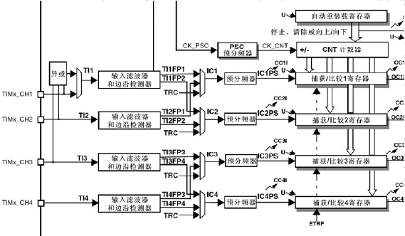
1.2 channel overview of input capture
Each acquisition / comparison channel is surrounded by an acquisition / comparison register (including shadow register), including the acquisition input part (digital filter, multiplexer and prescaler), and the output part (comparator and output control).
The capture / compare module consists of a preloaded register and a shadow register. The read-write process only operates on preloaded registers.
1) In capture mode, the capture occurs on the shadow register and then copied to the preload register.
2) In comparison mode, the contents of the preloaded register are copied into the shadow register, and then the contents of the shadow register are compared with the counter.
The input part samples the corresponding TIx input signal and generates a filtered signal TIxF. Then, an edge detector with polarity selection generates a signal (TIxFPx), which can be triggered as an input from the mode controller or as a capture control. The signal enters the capture register (ICxPS) through pre frequency division.
Summarize the work process in one sentence: by detecting timx_ For the edge signal on CHX channel, when the edge signal jumps (such as rising edge / falling edge), store the value of the current timer (TIMx_CNT) in the corresponding capture / comparison register (TIMx_CCRx) to complete a capture. At the same time, you can also configure whether to trigger interrupt / DMA during capture.
two Enter the captured workflow
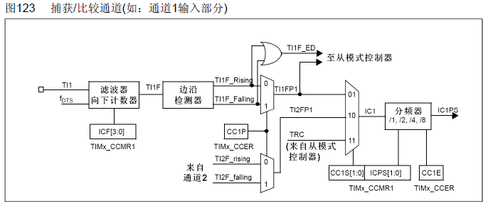
The input captured channel diagram is decomposed into four parts. The following four parts are analyzed to understand the working process of input capture:
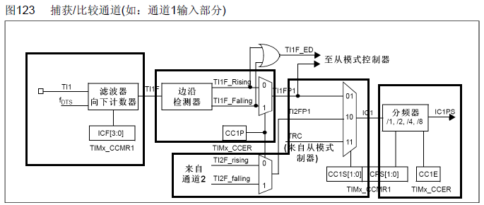
2.1 setting the input capture filter
Input capture filter IC1F[3:0], which is used to set the sampling frequency and digital filter length. Including: fCK_INT is the input frequency of the timer, and fDTS is based on timx_ The CKD[1:0] setting of CR1 is determined.
What does the function of the filter mean here? The digital filter consists of an event counter, which will produce an output jump after recording N events. In other words, if N consecutive samples are at high level, it indicates that this is an effective trigger and will enter the input capture interrupt (if set). In this way, the pulse signals with high-level pulse width less than 8 sampling periods can be filtered, so as to achieve the function of filtering.
two point two Set input snap polarity
Here is to set whether the capture event occurs on the rising edge or the falling edge.
two point three Set input capture mapping relationship
Since we only show the channel diagram of one channel, if there are several channels:
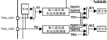
In TIMx_CH1 and timx_ In the case of CH2 two channels, we can see that in addition to timx_ The signal captured by ch1 can be connected to IC1, timx_ The signal captured by CH2 can be connected outside IC2, timx_ The signal captured by ch1 can also be connected to IC2 and timx_ The signal captured by CH2 can also be connected to IC1.
In general, we set it to timx_ The signal captured by ch1 can be connected to IC1, timx_ The signal captured by CH2 can be connected to IC2.
two point four Set input capture divider
The setting here is to trigger a capture every N events. That is, we can set it to trigger a capture every 2 rising edge events.
3 input capture related configuration register
three point one Capture / compare mode register 1 (TIMx_CCMR1)
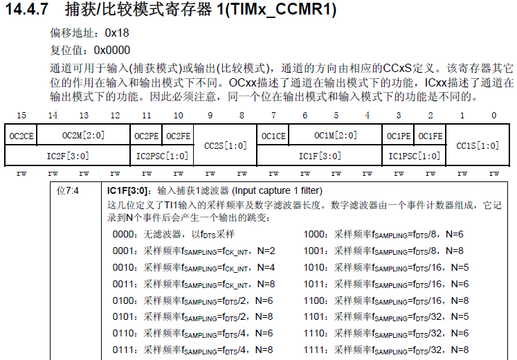
Function: in the input acquisition mode, determine the digital filter, channel mapping and pre frequency division coefficient.
three point two Capture / compare enable register (TIMx_CCER)
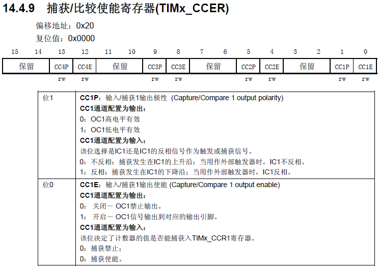
Function: in the input capture mode, determine the capture polarity and capture enable.
three point three Capture / compare register 1 (timx#u CCR1)
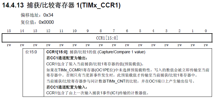
Function: in input capture mode, determine the count value of the last input capture event transmission.
4 input capture related configuration library functions
four point one 1 input initialization function
void TIM_ICInit(TIM_TypeDef* TIMx, TIM_ICInitTypeDef* TIM_ICInitStruct);
typedef struct
{
  uint16_t TIM_Channel; //Capture channels 1-4
  uint16_t TIM_ICPolarity; //Capture polarity
  uint16_t TIM_ICSelection; //Mapping relationship
  uint16_t TIM_ICPrescaler; //division factor
  uint16_t TIM_ICFilter;  //wave filter
} TIM_ICInitTypeDef;
Function: initialize acquisition channel, filter, acquisition polarity, mapping relationship, frequency division coefficient and other parameters.
Note: since the output initialization function separates the functions of all four channels, each defines a function, while the input initialization function does not. Therefore, in the input initialization function, you need to specify the capture channel.
four point two 1 parameter acquisition function
uint16_t TIM_GetCapture1(TIM_TypeDef* TIMx);
uint16_t TIM_GetCapture2(TIM_TypeDef* TIMx);
uint16_t TIM_GetCapture3(TIM_TypeDef* TIMx);
uint16_t TIM_GetCapture4(TIM_TypeDef* TIMx);
Function: select one of the four channels to determine the count value of the last input capture event transmission.
four point three 1 parameter setting function
void TIM_OC1PolarityConfig(TIM_TypeDef* TIMx, uint16_t TIM_OCPolarity);
void TIM_OC2PolarityConfig(TIM_TypeDef* TIMx, uint16_t TIM_OCPolarity);
void TIM_OC3PolarityConfig(TIM_TypeDef* TIMx, uint16_t TIM_OCPolarity);
void TIM_OC4PolarityConfig(TIM_TypeDef* TIMx, uint16_t TIM_OCPolarity);
Function: select one of the four channels and set the channel polarity. Generally, the channel polarity has been set in the initialization function, which is used for modifications other than initialization.
five General steps for input capture
Example requirements: use channel 1 (PA0) of TIM5 as input capture, capture the pulse width of high level on PA0 (input high level with WK_UP key), and print the high level pulse time through serial port.
1) Initialization timer and clock of IO corresponding to channel: RCC_APB1PeriphClockCmd();
2) Initialize the IO port, and the mode is input. Calling function: GPIO_Init();
3) Initialize timer ARR, PSC. Calling function: TIM_TimeBaseInit();
4) Initialize the input capture channel. Calling function: TIM_ICInit();
5) If you want to turn on capture interrupt. Calling function: TIM_ITConfig(); NVIC_Init();
6) Enable timer. Calling function: TIM_Cmd();
7) Write an interrupt service function. Calling function: TIMx_IRQHandler().
Follow this general procedure to perform a simple input capture procedure:
//Timer 5 channel 1 input capture configuration

TIM_ICInitTypeDef  TIM5_ICInitStructure;

void TIM5_Cap_Init(u16 arr,u16 psc)
{
	GPIO_InitTypeDef GPIO_InitStructure;
	TIM_TimeBaseInitTypeDef  TIM_TimeBaseStructure;
   	NVIC_InitTypeDef NVIC_InitStructure;

   //Enable timer and associated IO clock
	RCC_APB1PeriphClockCmd(RCC_APB1Periph_TIM5, ENABLE);	//Enable TIM5 clock
 	RCC_APB2PeriphClockCmd(RCC_APB2Periph_GPIOA, ENABLE);  //Enable GPIOA clock

   //Set remapping as required. It is not required here, so it is omitted


   //Initialize IO port as function 	 Set this pin as input 	 GPIOA.0
	GPIO_InitStructure.GPIO_Pin  = GPIO_Pin_0;  //PA0 clear previous settings
	GPIO_InitStructure.GPIO_Mode = GPIO_Mode_IPD; //PA0 input
	GPIO_Init(GPIOA, &GPIO_InitStructure);
	GPIO_ResetBits(GPIOA,GPIO_Pin_0);						 //PA0 drop down

	//Initialize timer 5 TIM5
	TIM_TimeBaseStructure.TIM_Period = arr; //Set the counter auto reload value
	TIM_TimeBaseStructure.TIM_Prescaler =psc; 	//Prescaler
	TIM_TimeBaseStructure.TIM_ClockDivision = TIM_CKD_DIV1; //Set clock division: TDTS = Tck_tim
	TIM_TimeBaseStructure.TIM_CounterMode = TIM_CounterMode_Up;  //TIM up count mode
	TIM_TimeBaseInit(TIM5, &TIM_TimeBaseStructure); //According to Tim_ The parameter specified in timebaseinitstruct initializes the time base unit of TIMx

	//Initialize TIM5 input capture parameters
	TIM5_ICInitStructure.TIM_Channel = TIM_Channel_1; //CC1S=01  	 Select input IC1 to map to TI1
  	TIM5_ICInitStructure.TIM_ICPolarity = TIM_ICPolarity_Rising;	//Rising edge capture
  	TIM5_ICInitStructure.TIM_ICSelection = TIM_ICSelection_DirectTI; //Map to TI1
  	TIM5_ICInitStructure.TIM_ICPrescaler = TIM_ICPSC_DIV1;	 //Configure input frequency division without frequency division
  	TIM5_ICInitStructure.TIM_ICFilter = 0x00;//IC1F=0000 configure input filter without filtering
  	TIM_ICInit(TIM5, &TIM5_ICInitStructure);

	//Interrupt packet initialization
	NVIC_InitStructure.NVIC_IRQChannel = TIM5_IRQn;  //TIM3 interrupt
	NVIC_InitStructure.NVIC_IRQChannelPreemptionPriority = 2;  //Preemptive priority level 2
	NVIC_InitStructure.NVIC_IRQChannelSubPriority = 0;  //From priority level 0
	NVIC_InitStructure.NVIC_IRQChannelCmd = ENABLE; //IRQ channel enabled
	NVIC_Init(&NVIC_InitStructure);  //According to NVIC_ Initializes the peripheral NVIC register with the parameters specified in initstruct

   //Allow update interrupt
	TIM_ITConfig(TIM5,TIM_IT_Update|TIM_IT_CC1,ENABLE);//Allow update interrupt and CC1IE capture interrupt

   //Enable timer
   	TIM_Cmd(TIM5,ENABLE ); 	//Enable timer 5

}

u8  TIM5CH1_CAPTURE_STA=0;	//Input capture status
u16	TIM5CH1_CAPTURE_VAL;	//Enter capture value

//Timer 5 interrupt service routine
void TIM5_IRQHandler(void)
{

 	if((TIM5CH1_CAPTURE_STA&0X80)==0)//Not captured successfully
	{
		if (TIM_GetITStatus(TIM5, TIM_IT_Update) != RESET)

		{
			if(TIM5CH1_CAPTURE_STA&0X40)//High level has been captured
			{
				if((TIM5CH1_CAPTURE_STA&0X3F)==0X3F)//The high level is too long
				{
					TIM5CH1_CAPTURE_STA|=0X80;//Tag successfully captured once
					TIM5CH1_CAPTURE_VAL=0XFFFF;
				}else TIM5CH1_CAPTURE_STA++;
			}
		}
	if (TIM_GetITStatus(TIM5, TIM_IT_CC1) != RESET)//Capture event occurred in capture 1
		{
			if(TIM5CH1_CAPTURE_STA&0X40)		//A falling edge was captured
			{
				TIM5CH1_CAPTURE_STA|=0X80;		//The flag successfully captures a high-level pulse width
				TIM5CH1_CAPTURE_VAL=TIM_GetCapture1(TIM5);
		   		TIM_OC1PolarityConfig(TIM5,TIM_ICPolarity_Rising); //CC1P=0 set as rising edge capture
			}else  								//Not yet started, first capture rising edge
			{
				TIM5CH1_CAPTURE_STA=0;			//empty
				TIM5CH1_CAPTURE_VAL=0;
	 			TIM_SetCounter(TIM5,0);
				TIM5CH1_CAPTURE_STA|=0X40;		//The tag captures the rising edge
		   		TIM_OC1PolarityConfig(TIM5,TIM_ICPolarity_Falling);		//CC1P=1 set as falling edge capture
			}
		}
 	}

    TIM_ClearITPendingBit(TIM5, TIM_IT_CC1|TIM_IT_Update); //Clear interrupt flag bit

}
extern u8 TIM5CH1_CAPTURE_STA; //Input capture status
extern u16 TIM5CH1_CAPTURE_VAL; //Enter capture value
int main(void)
{
u32 temp=0;
delay_init(); //Delay function initialization
NVIC_PriorityGroupConfig(NVIC_PriorityGroup_2); //Set NVIC interrupt packet 2: 2-bit preemption priority and 2-bit response priority
uart_init(115200); //The serial port is initialized to 115200
TIM5_Cap_Init(0XFFFF,72-1); //Count at 1Mhz
while(1)
{
delay_ms(10);
if(TIM5CH1_CAPTURE_STA&0X80)//Successfully captured a rising edge
{
temp=TIM5CH1_CAPTURE_STA&0X3F;
temp*=65536;//Total overflow time
temp+=TIM5CH1_CAPTURE_VAL;//Get the total high level time
printf("HIGH:%d us\r\n",temp);//Print total leveling time
TIM5CH1_CAPTURE_STA=0;//Turn on next capture
}
}
}five point one Code logic
The initialization part of input capture here is relatively simple, just refer to the general steps. But in the interrupt handler TIM5_IRQHandler() is difficult. Why is it complicated?
As we capture the input, once the rising edge is captured, set the current value of the counter to 0 and let it start counting again from 0:
TIM_SetCounter(TIM5,0);
However, if the pulse length is too wide, that is, a cycle from counting from 0 to automatic reload value ends, and the pulse still does not end. In this case, it is obvious that you can't just record the current value of the last counter.
The solution to this problem:
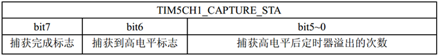
Set a variable TIM5CH1_CAPTURE_STA, bit5-0 is the number of times the timer overflows after capturing the high level, bit6 is the capture high level flag, and bit7 is the capture completion flag.
Set two interrupts at the same time (update interrupt and capture interrupt):
TIM_ITConfig(TIM5,TIM_IT_Update|TIM_IT_CC1,ENABLE);//Allow update interrupt and CC1IE capture interrupt
In the interrupt processing function, first judge whether the capture is successful. If the capture is successful, it means that nothing needs to be done in the pulse low-level stage; If the capture is not successful, it indicates that it is in the high-level phase of the pulse, you need to continue to judge the interrupt type, and then process it separately. In the update interrupt, it indicates that the pulse length is too long at this time, TIM5CH1_CAPTURE_STA plus 1. In the capture interrupt, judge whether the captured edge is a rising edge. If so, the current value of the counter is cleared and TIM5CH1_CAPTURE_STA is cleared, the flag is marked at the same time, and the falling edge capture of polarity is set; If not, mark that the capture is complete, save the value of the current counter, and set the polarity rising edge capture.
five point two extern keyword
In C language, extern can be placed in front of variables or functions to represent the definition of variables or functions. In other files, it prompts the compiler to find the definition of such variables and functions in other modules.
Note: extern al variables can be declared multiple times, but defined only once.