-
EV1527 Wireless Communication
Let's start with the data format of this communication protocol. This picture is intercepted in my manual.
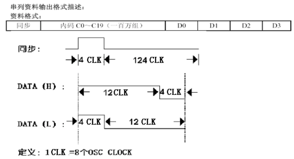
- Everyone calculates the period according to the type of MCU. My name is STM32f103vb (4CLK is roughly 350um).
- Logic 1 or logic 0 is sent in the order of synchronization code before DATA.
-
Wireless communication transmission mode
- Sending is very simple, just according to the data format, that is, there are changes in the processing of data. No matter what data you want to send, the hexadecimal system will eventually be converted to the binary system and sent to 01, from low to high.
- Initialization functions are in send mode.
/*
@Description High and low output level according to EV1527 protocol
@mode Logic 0 or 1
*/
void S433_SendBit(u8 mode){

    if(mode==1)
    {
        PEout(9)=1;
        SysTick_Delay_Us(350*3);
        PEout(9)=0;
        SysTick_Delay_Us(350);

    }else if(mode==0)
    {
        PEout(9)=1;
        SysTick_Delay_Us(350);
        PEout(9)=0;
        SysTick_Delay_Us(350*3);

    }else{
        debug_led(1, LED_TOGGLE);
    }

}

/*
@Description Synchronization pulse (or boot)
*/
//Synchronization Pulse 4:124
void Sync_Pulse(){


    PEout(9)=1;
    SysTick_Delay_Us(350);
    PEout(9)=0;
    SysTick_Delay_Us(350*31);

}

/*
@Description Send Code Function Call
@num 24 Bit Binary 10-digit Number
*/
//Processing the sent 10-digit number, which can be changed according to the requirements
void S433_Send(u32 num){
u8 i;
u32 result=24,temp;
temp = num;

Sync_Pulse();

    while(result){
        i = temp%2; //Remaining the decimal number equals the lowest binary number
        S433_SendBit(i);
        temp = temp/2;//Divide two and take the whole
        result--;
    }

}
-
Wireless Communication Receiving Mode
Receiving is much more complicated than sending.
By triggering the external interrupt processing function, the data can be detected. Every time the rising or falling edge is triggered, the time is recorded. According to the length of time, the clutter, synchronous wave or data wave can be judged. The key of receiving is to judge.
The following section is the initialization of some values and the initialization of IO pins.
static volatile unsigned long long rx433_previous_time = 0;//Last entry interruption time
static volatile unsigned char Sync_Pulse_begin =0;//Detecting Synchronization Pulse Integrity 1 is Synchronization Pulse
static volatile unsigned char  rx433_begin= 0;//Synchronized Pulse Open Sign 1 Open 0 Not Open
static volatile unsigned short interval_previous_time=0;//Last interval
////////////
static volatile u8 Rx433Cnt=0;
static volatile u8 Rx433bit[30]={0};
static volatile u8 rxbit=0;
static volatile u8 firstbit=0;
static volatile u32 Rx433[64]={0};
///////////


//Initialization of pins refers to general IO Pin communication
void S433_SR_Init(){

    GPIO_InitTypeDef GPIO_InitStructure;
    EXTI_InitTypeDef EXTI_InitStructure;
    NVIC_InitTypeDef NVIC_InitStructure;
    RCC_APB2PeriphClockCmd(RCC_APB2Periph_GPIOE,ENABLE); //Enable GPIOE Clock

    //E9 Enable
    GPIO_InitStructure.GPIO_Pin = GPIO_Pin_9;
    GPIO_InitStructure.GPIO_Mode = GPIO_Mode_Out_PP;
    GPIO_InitStructure.GPIO_Speed = GPIO_Speed_50MHz;
    GPIO_Init(GPIOE, &GPIO_InitStructure);
    GPIO_ResetBits(GPIOE, GPIO_Pin_9);//  Pin pull down
    //Receive E7
    RCC_APB2PeriphClockCmd(RCC_APB2Periph_AFIO,ENABLE);
    GPIO_InitStructure.GPIO_Pin = GPIO_Pin_7;
    GPIO_InitStructure.GPIO_Mode = GPIO_Mode_IPD;   //Input is low
    GPIO_InitStructure.GPIO_Speed = GPIO_Speed_50MHz;
    GPIO_Init(GPIOE, &GPIO_InitStructure);
    GPIO_EXTILineConfig(GPIO_PortSourceGPIOE,GPIO_PinSource7);

    EXTI_InitStructure.EXTI_Line=EXTI_Line7;
    EXTI_InitStructure.EXTI_Mode=EXTI_Mode_Interrupt;
    EXTI_InitStructure.EXTI_Trigger= EXTI_Trigger_Rising_Falling;
    EXTI_InitStructure.EXTI_LineCmd=ENABLE;
    EXTI_Init(&EXTI_InitStructure);

    NVIC_InitStructure.NVIC_IRQChannel=EXTI9_5_IRQn;
    NVIC_InitStructure.NVIC_IRQChannelPreemptionPriority=2;
    NVIC_InitStructure.NVIC_IRQChannelSubPriority=2;
    NVIC_InitStructure.NVIC_IRQChannelCmd=ENABLE;
    NVIC_Init(&NVIC_InitStructure);


}
Synchronization Wave Judgment and Detection of Transmitting Completeness
/*
@Description Judging whether it is synchronous pulse
@pre Number of previous periods
@now Number of current periods
@return rebit Synchronization success synerror is not synchronization pulse
*/
u8 Sync_PulseRx(u8 pre,u8 now){

    if(!PEin(7)){//Every drop edge begins to be measured.

    Sync_Pulse_begin=1;//Start to detect synchronous pulses


    }else if(Sync_Pulse_begin==1&&(pre==1)&&(now==31)){//When the condition is satisfied, the time pulse can be judged.

    Sync_Pulse_begin=0;//Synchronization successfully turns off the synchronization code
    rx433_begin=1;//Official start of data transmission
    rxbit=0;//Zero the number of bits of data
    firstbit=1;//Wait for the next jump to begin
    return success;
    }else{

    Sync_Pulse_begin=0;//Not Pulse Set 0
    return synerror;
    }
    return rxbit;

}


/*
@Description Judgment logic 0 and 1
@pre Number of previous periods
@now Number of current periods
@return  rxerror Receiving overstep
*/
u8 RX433_Bit(u8 pre,u8 now){
if(firstbit==1){
firstbit=0;//This step prevents direct access to this function after boot completion
}else if(rx433_begin==1&&PEin(7)){//Rising edge detection

    if(rxbit>24){//Can be added to 24 to show that a frame of data has been obtained
    rxbit=0;//Zeroing
    rx433_begin=0;//Return to zero and prepare for the next group

    }

    if(now==3&&pre==1){//Logic 0
        Rx433bit[rxbit]=0;
        rxbit++;
    }else if(now==1&&pre==3){//Logic 1
        Rx433bit[rxbit]=1;
        rxbit++;
    }else{
    //Run away
    rx433_begin=0;
    rxbit=0;
    return rxerror;
    }

return rxbit-1;
}
return 0;
}
External interrupt handlers are often triggered because they receive all kinds of clutter, but cannot enter the key handler.
//First Judge Synchronization Pulse
//If it is a synchronous pulse, begin Open Judgment Data Receive and Judge Situation
//If the data receiving bit exceeds the expected 24 bits, the data receiving bit exceeds the expected 24 bits.
//If you receive it half way, ignore it and start with the next paragraph.
void EXTI9_5_IRQHandler(void){

    if(EXTI_GetITStatus(EXTI_Line7)!=RESET)
    {
        unsigned char skip_index = 0;//Several data bits this time
        unsigned char skip_pervious_index=0;//Previous data bits
        unsigned long long now_time=sys_micros();//At the moment
        unsigned short interval_time = now_time - rx433_previous_time;//Calculate the duration of a level state
        rx433_previous_time = now_time;//Prepare for the next calculation
        skip_index = (interval_time/349);//Get a multiple of the duration of a certain level and calculate several high or low levels
        skip_pervious_index=(interval_previous_time/349);//It's just the same as the previous one.

        Sync_PulseRx(skip_pervious_index,skip_index);//Synchronization Pulse
        RX433_Bit(skip_pervious_index,skip_index);//Data bits

        if(interval_time<45000){
        interval_previous_time = interval_time;

        }else{
        interval_previous_time = 0;

        }
        EXTI_ClearITPendingBit(EXTI_Line7);//Clear interrupt pending flag

    }

}