1. UART introduction
Universal synchronous asynchronous receiver and transmitter is a
A serial communication device, which can flexibly exchange full duplex data with external devices. There is another difference from USART
UART(Universal Asynchronous Receiver and Transmitter) cuts out the same data on the basis of USART
Step communication function, only asynchronous communication. The simple distinction between synchronous and asynchronous is to see whether external clock input is required during communication
The serial communication we usually use is basically UART.
Serial communication generally transmits data in frame format, that is, frame by frame transmission. Each frame contains start signal and number
According to the information, stop information, and possibly verification information. USART has specific provisions on these transmission parameters, of course
There is not only one parameter value. Many parameter values can be customized to enhance their compatibility.
USART meets the requirements of external equipment for the industrial standard NRZ asynchronous serial data format, and uses fractional wave
The special rate generator can provide a variety of baud rates, making it more widely used. USART supports synchronous one-way communication and
Half duplex single line communication; It also supports local interconnect network LIN, smart card protocol and LrDA (infrared data association)
(II) SIR ENDEC specification.
2. Procedure
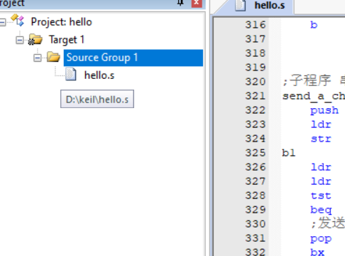
Create a new project, select f103 chip, don't select anything in the software package, and then create an. s file. After creation, it is like this
Enter the code in the. s file
;RCC Register address mapping
RCC_BASE            EQU    0x40021000
RCC_CR              EQU    (RCC_BASE + 0x00)
RCC_CFGR            EQU    (RCC_BASE + 0x04)
RCC_CIR             EQU    (RCC_BASE + 0x08)
RCC_APB2RSTR        EQU    (RCC_BASE + 0x0C)
RCC_APB1RSTR        EQU    (RCC_BASE + 0x10)
RCC_AHBENR          EQU    (RCC_BASE + 0x14)
RCC_APB2ENR         EQU    (RCC_BASE + 0x18)
RCC_APB1ENR         EQU    (RCC_BASE + 0x1C)
RCC_BDCR            EQU    (RCC_BASE + 0x20)
RCC_CSR             EQU    (RCC_BASE + 0x24)

;AFIO Register address mapping
AFIO_BASE           EQU    0x40010000
AFIO_EVCR           EQU    (AFIO_BASE + 0x00)
AFIO_MAPR           EQU    (AFIO_BASE + 0x04)
AFIO_EXTICR1        EQU    (AFIO_BASE + 0x08)
AFIO_EXTICR2        EQU    (AFIO_BASE + 0x0C)
AFIO_EXTICR3        EQU    (AFIO_BASE + 0x10)
AFIO_EXTICR4        EQU    (AFIO_BASE + 0x14)

;GPIOA Register address mapping
GPIOA_BASE          EQU    0x40010800
GPIOA_CRL           EQU    (GPIOA_BASE + 0x00)
GPIOA_CRH           EQU    (GPIOA_BASE + 0x04)
GPIOA_IDR           EQU    (GPIOA_BASE + 0x08)
GPIOA_ODR           EQU    (GPIOA_BASE + 0x0C)
GPIOA_BSRR          EQU    (GPIOA_BASE + 0x10)
GPIOA_BRR           EQU    (GPIOA_BASE + 0x14)
GPIOA_LCKR          EQU    (GPIOA_BASE + 0x18)

;GPIO C Mouth control
GPIOC_BASE          EQU    0x40011000
GPIOC_CRL           EQU    (GPIOC_BASE + 0x00)
GPIOC_CRH           EQU    (GPIOC_BASE + 0x04)
GPIOC_IDR           EQU    (GPIOC_BASE + 0x08)
GPIOC_ODR           EQU    (GPIOC_BASE + 0x0C)
GPIOC_BSRR          EQU    (GPIOC_BASE + 0x10)
GPIOC_BRR           EQU    (GPIOC_BASE + 0x14)
GPIOC_LCKR          EQU    (GPIOC_BASE + 0x18)

;Serial port 1 control
USART1_BASE         EQU    0x40013800
USART1_SR           EQU    (USART1_BASE + 0x00)
USART1_DR           EQU    (USART1_BASE + 0x04)
USART1_BRR          EQU    (USART1_BASE + 0x08)
USART1_CR1          EQU    (USART1_BASE + 0x0c)
USART1_CR2          EQU    (USART1_BASE + 0x10)
USART1_CR3          EQU    (USART1_BASE + 0x14)
USART1_GTPR         EQU    (USART1_BASE + 0x18)

;NVIC Register address
NVIC_BASE           EQU    0xE000E000
NVIC_SETEN          EQU    (NVIC_BASE + 0x0010)
;SETENA Starting address of register array
NVIC_IRQPRI         EQU    (NVIC_BASE + 0x0400)
;Start address of interrupt priority register array
NVIC_VECTTBL        EQU    (NVIC_BASE + 0x0D08)
;Address of vector table offset register
NVIC_AIRCR          EQU    (NVIC_BASE + 0x0D0C)
;Address of application interrupt and reset control register
SETENA0             EQU    0xE000E100
SETENA1             EQU    0xE000E104


;SysTick Register address
SysTick_BASE        EQU    0xE000E010
SYSTICKCSR          EQU    (SysTick_BASE + 0x00)
SYSTICKRVR          EQU    (SysTick_BASE + 0x04)

;FLASH Buffer register address image
FLASH_ACR           EQU    0x40022000

;SCB_BASE           EQU    (SCS_BASE + 0x0D00)

MSP_TOP             EQU    0x20005000
;Starting value of main stack
PSP_TOP             EQU    0x20004E00
;Process stack start value

BitAlias_BASE       EQU    0x22000000
;Bit alias area start address
Flag1               EQU    0x20000200
b_flas              EQU    (BitAlias_BASE + (0x200*32) + (0*4))
;Bit address
b_05s               EQU    (BitAlias_BASE + (0x200*32) + (1*4))
;Bit address
DlyI                EQU    0x20000204
DlyJ                EQU    0x20000208
DlyK                EQU    0x2000020C
SysTim              EQU    0x20000210


;Constant definition
Bit0                EQU    0x00000001
Bit1                EQU    0x00000002
Bit2                EQU    0x00000004
Bit3                EQU    0x00000008
Bit4                EQU    0x00000010
Bit5                EQU    0x00000020
Bit6                EQU    0x00000040
Bit7                EQU    0x00000080
Bit8                EQU    0x00000100
Bit9                EQU    0x00000200
Bit10               EQU    0x00000400
Bit11               EQU    0x00000800
Bit12               EQU    0x00001000
Bit13               EQU    0x00002000
Bit14               EQU    0x00004000
Bit15               EQU    0x00008000
Bit16               EQU    0x00010000
Bit17               EQU    0x00020000
Bit18               EQU    0x00040000
Bit19               EQU    0x00080000
Bit20               EQU    0x00100000
Bit21               EQU    0x00200000
Bit22               EQU    0x00400000
Bit23               EQU    0x00800000
Bit24               EQU    0x01000000
Bit25               EQU    0x02000000
Bit26               EQU    0x04000000
Bit27               EQU    0x08000000
Bit28               EQU    0x10000000
Bit29               EQU    0x20000000
Bit30               EQU    0x40000000
Bit31               EQU    0x80000000


;Vector table
    AREA RESET, DATA, READONLY
    DCD    MSP_TOP            ;Initialize main stack
    DCD    Start              ;Reset vector
    DCD    NMI_Handler        ;NMI Handler
    DCD    HardFault_Handler  ;Hard Fault Handler
    DCD    0
    DCD    0
    DCD    0
    DCD    0
    DCD    0
    DCD    0
    DCD    0
    DCD    0
    DCD    0
    DCD    0
    DCD    0
    DCD    SysTick_Handler    ;SysTick Handler
    SPACE  20                 ;Reserved space 20 bytes


;Code snippet
    AREA |.text|, CODE, READONLY
    ;Main program start
    ENTRY
    ;Instructs the program to execute from here
Start
    ;Clock system settings
    ldr    r0, =RCC_CR
    ldr    r1, [r0]
    orr    r1, #Bit16
    str    r1, [r0]
    ;Enable external crystal oscillator
    ;Start external 8 M Crystal oscillator

ClkOk
    ldr    r1, [r0]
    ands   r1, #Bit17
    beq    ClkOk
    ;Wait for the external crystal oscillator to be ready
    ldr    r1,[r0]
    orr    r1,#Bit17
    str    r1,[r0]
    ;FLASH Buffer
    ldr    r0, =FLASH_ACR
    mov    r1, #0x00000032
    str    r1, [r0]

    ;set up PLL The PLL magnification is 7,HSE Input no frequency division
    ldr    r0, =RCC_CFGR
    ldr    r1, [r0]
    orr    r1, #(Bit18 :OR: Bit19 :OR: Bit20 :OR: Bit16 :OR: Bit14)
    orr    r1, #Bit10
    str    r1, [r0]
    ;start-up PLL Phase locked loop
    ldr    r0, =RCC_CR
    ldr    r1, [r0]
    orr    r1, #Bit24
    str    r1, [r0]
PllOk
    ldr    r1, [r0]
    ands   r1, #Bit25
    beq    PllOk
    ;choice PLL Clock as system clock
    ldr    r0, =RCC_CFGR
    ldr    r1, [r0]
    orr    r1, #(Bit18 :OR: Bit19 :OR: Bit20 :OR: Bit16 :OR: Bit14)
    orr    r1, #Bit10
    orr    r1, #Bit1
    str    r1, [r0]
    ;other RCC Related settings
    ldr    r0, =RCC_APB2ENR
    mov    r1, #(Bit14 :OR: Bit4 :OR: Bit2)
    str    r1, [r0]


    ;PA9 Serial port 0 transmitting pin
    ldr    r0, =GPIOA_CRH
    ldr    r1, [r0]
    orr    r1, #(Bit4 :OR: Bit5)
    ;PA.9 Output mode,Maximum speed 50 MHz
    orr    r1, #Bit7
    and    r1, #~Bit6
    ;10: Multiplexing function push-pull output mode
    str    r1, [r0]


    ldr    r0, =USART1_BRR
    mov    r1, #0x271
    str    r1, [r0]
    ;Configure baud rate-> 115200

    ldr    r0, =USART1_CR1
    mov    r1, #0x200c
    str    r1, [r0]
    ;USART Module total enable send and receive enable
    ;71 02 00 00   2c 20 00 00

    ;AFIO Parameter setting
    ;Systick Parameter setting
    ldr    r0, =SYSTICKRVR
    ;Systick Initial installation value
    mov    r1, #9000
    str    r1, [r0]
    ldr    r0, =SYSTICKCSR
    ;set up,start-up Systick
    mov    r1, #0x03
    str    r1, [r0]

    ;Switch to user level line program mode
    ldr    r0, =PSP_TOP
    ;Initialize thread stack
    msr    psp, r0
    mov    r0, #3
    msr    control, r0

    ;initialization SRAM register
    mov    r1, #0
    ldr    r0, =Flag1
    str    r1, [r0]
    ldr    r0, =DlyI
    str    r1, [r0]
    ldr    r0, =DlyJ
    str    r1, [r0]
    ldr    r0, =DlyK
    str    r1, [r0]
    ldr    r0, =SysTim
    str    r1, [r0]

;Main cycle
main
    ldr    r0, =Flag1
    ldr    r1, [r0]
    tst    r1, #Bit1
    ;SysTick Generate 0.5s,Set bit 1
    beq    main                  ;0.5s The flag is not set yet

    ;0.5s The flag has been set
    ldr    r0, =b_05s
    ;Bit band operation reset 0.5s sign
    mov    r1, #0
    str    r1, [r0]

    mov    r0, #'H'
    bl     send_a_char

	mov    r0, #'e'
    bl     send_a_char

	mov    r0, #'l'
    bl     send_a_char

	mov    r0, #'l'
    bl     send_a_char

	mov    r0, #'o'
    bl     send_a_char

	mov    r0, #' '
    bl     send_a_char

	mov    r0, #'W'
    bl     send_a_char

	mov    r0, #'o'
    bl     send_a_char

	mov    r0, #'r'
    bl     send_a_char

	mov    r0, #'l'
    bl     send_a_char

	mov    r0, #'d'
    bl     send_a_char

	mov    r0, #'\n'
    bl     send_a_char

	b      main


;Subroutine serial port 1 sends a character
send_a_char
    push   {r0 - r3}
    ldr    r2, =USART1_DR
    str    r0, [r2]
b1
    ldr    r2, =USART1_SR
    ldr    r2, [r2]
    tst    r2, #0x40
    beq    b1
    ;Send complete(Transmission complete)wait for
    pop    {r0 - r3}
    bx     lr

;Abnormal program
NMI_Handler
    bx     lr


HardFault_Handler
    bx     lr

SysTick_Handler
    ldr    r0, =SysTim
    ldr    r1, [r0]
    add    r1, #1
    str    r1, [r0]
    cmp    r1, #500
    bcc    TickExit
    mov    r1, #0
    str    r1, [r0]
    ldr    r0, =b_05s
    ;The clock tick counter is set to 0 when it is greater than or equal to 500 times of clearing.5s Flag bit
    ;Bit band operation set 1
    mov    r1, #1
    str    r1, [r0]
TickExit
    bx     lr

    ALIGN
    ;By using zero or null instructions NOP fill,Aligns the current position with a specified boundary
    END
Then burn the program
3. Operation
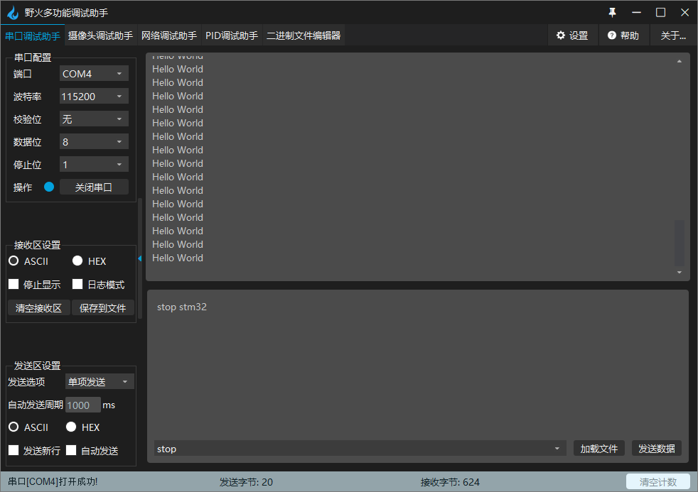 Run successfully
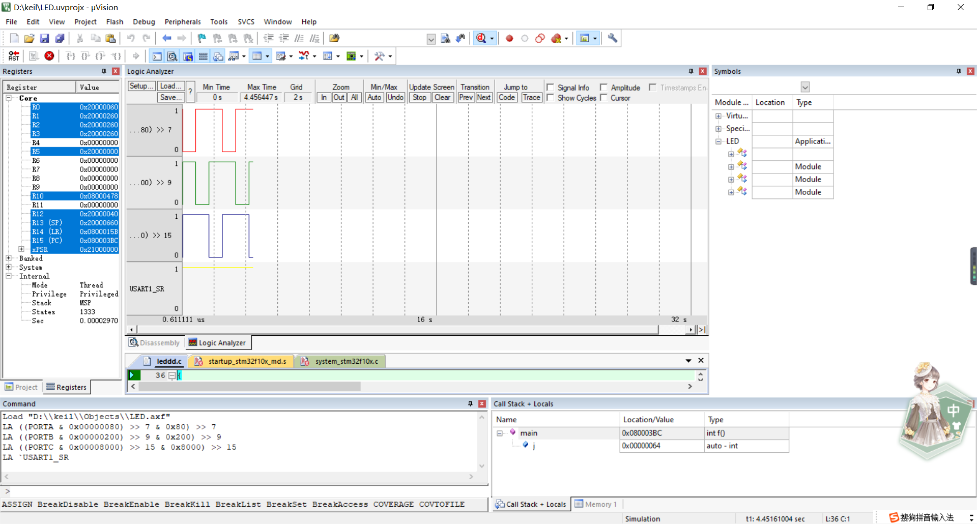
4. Use keil software to simulate logic analysis and observe the timing waveform of pins
When running the simulation program, you can see that the level bit will change every other period of time, which represents that the burned program is outputting periodically
5. Summary
It's still difficult to send information to the computer through the serial port. Most of the time, you can only draw a gourd and ladle according to the gourd, and you can't understand it yourself