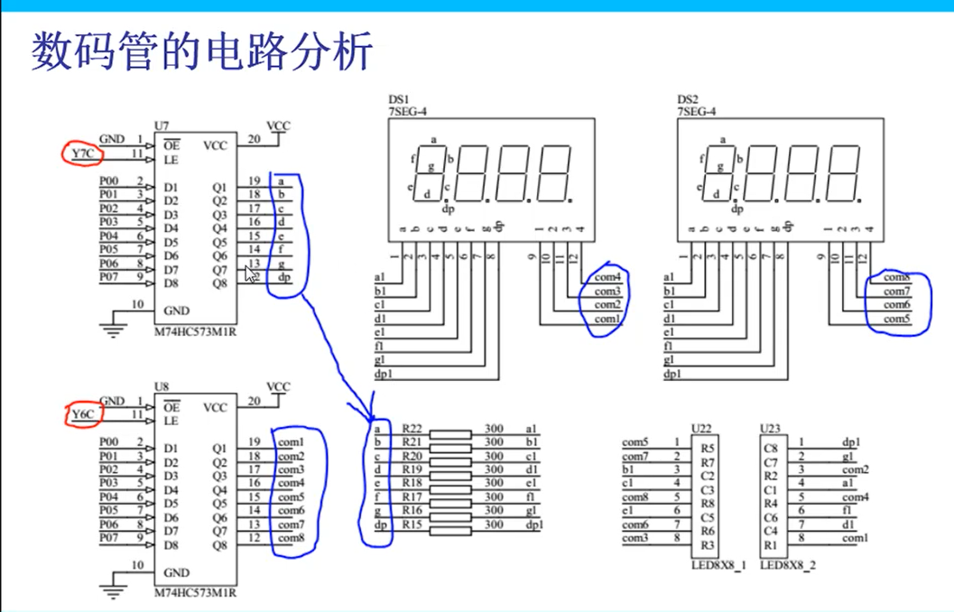
Schematic diagram of nixie tube circuit


Hardware implementation principle
1. Circuit analysis
Firstly, the data is latched by M74HC573MIR latch. Firstly, the segment code is output by Y7C enable terminal, and the bit code is output by Y6C enable terminal. The resistance here plays a role of current limiting.
2. Digital tube analysis
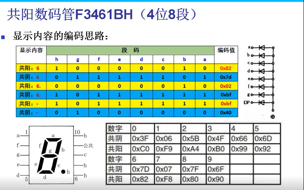
Common positive (negative) nixie tube: each nixie tube is made up of eight diodes, so the positive (negative) poles of the diodes are shared, and the high (low) level of the diode is common to the positive (negative) nixie tube.
Segment code display: segment code displays the highest bit from dp (h) - > G - > F - > e - > D - > C - > b - > a. The diode position of the common cathode nixie tube is 1, and the binary number formed is converted into hexadecimal number.
code implementation
 1 #include "reg52.h"
 2
 3 typedef unsigned int u16;
 4 typedef unsigned char u8;
 5
 6 /*u8 code smgduan[18]=
 7         {0xc0,0xf9,0xa4,0xb0,0x99,0x92,0x82,0xf8,
 8          0x80,0x90,0x88,0x83,0xc6,0xa1,0x86,0x8e};*/ //Gongyang
 9
10 u8 code smgduan[18]=
11         {0x3f,0x06,0x5b,0x4f,0x66,0x6d,0x7d,0x07,
12          0x7f,0x6f,0x77,0x7c,0x39,0x5e,0x79,0x71};
13
14 void delay(u16 i)
15 {
16     while(i--);
17     while(i--);
18 }
19
20 void HC138Init(u8 i)
21 {
22     switch(i)
23     {
24         case 4:
25             P2 = (P2 & 0x1f) | 0x80;
26         break;
27
28         case 5:
29             P2 = (P2 & 0x1f) | 0xa0;
30         break;
31
32         case 6:
33             P2= (P2 & 0x1f) | 0xc0;
34         break;
35
36         case 7:
37             P2 = (P2 & 0x1f) | 0xe0;
38
39     }
40 }
41
42 void Display(u8 dat,unsigned pos)
43 {
44     HC138Init(6); // Position of digital tube
45     P0 = 0x01 << pos;
46     HC138Init(7); // Contents of digital tube
47     P0 = dat;
48 }
49
50 void DigDisplay()
51 {
52     u8 i,j;
53     for(i=0;i<8;i++)
54     {
55         for(j=0;j<10;j++)
56         {
57             Display(smgduan[j],i);
58             delay(60000);
59         }
60     }
61     for(j=0;j<16;j++)
62     {
63         HC138Init(6);
64         P0 = 0xff;
65         HC138Init(7);
66         P0 = smgduan[j];
67         delay(60000);
68     }
69
70 }
71
72 void main()
73 {
74     while(1)
75     {
76         DigDisplay();
77     }
78 }