Some understanding of compiled code
ARM Cortex-M underlying technology -- principle and application of compiling kernel
Reference website:
https://www.cnblogs.com/39950436-myqq/p/11545140.html
1. Definition of compilation link
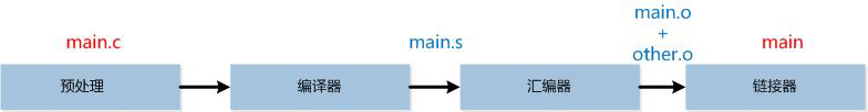
No matter how simple the code we write, we must go through the process of "compiling -- > linking" to generate executable files:
- Compilation is to "translate" the source code we write into a binary format that can be recognized by the computer. They exist in the form of object files;
- Linking is a "packaging" process, which combines all target files and system components into an executable file.
In terms of embedded, there are many compilers for C language. There are different compilers on different platforms, such as:
- Visual C + + developed by Microsoft is commonly used under Windows. It is integrated in Visual Studio and is generally not used alone;
- GCC developed by GUN is commonly used under Linux, and many Linux distributions come with GCC;
- LLVM/Clang is commonly used in Mac, which is integrated in Xcode (GCC was integrated in Xcode before, but it was changed to LLVM/Clang due to the mismatch of GCC. The performance of LLVM/Clang is more powerful than GCC).
In other words, when developing on windows platform, most of the development tools we choose are to help us integrate some compilers. We only need to configure the interface. Here I want to know how to use these compilation and linking tools in Keil development environment.
The compilation link in keil is as follows. The compilation connector will be explained below:
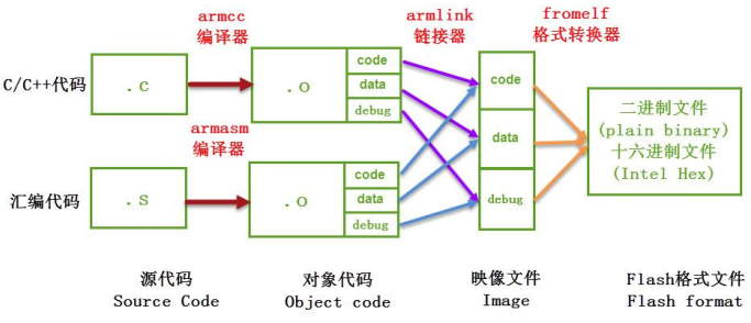
2. Keil's compilation link
When we compile a project with Keil, the contents in the following output box are as follows:
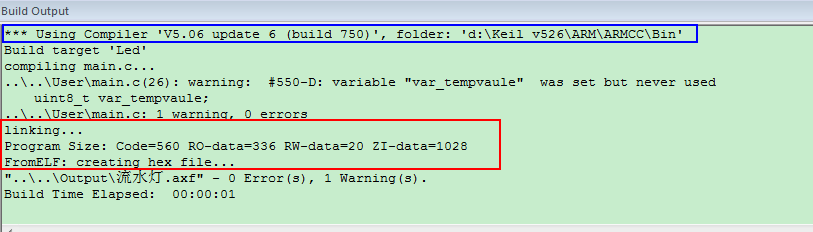
Compiler compiler, you can see the compiler in disk D of our computer, D:\Keil_v526\ARM\ARMCC\bin, as shown in the figure below:
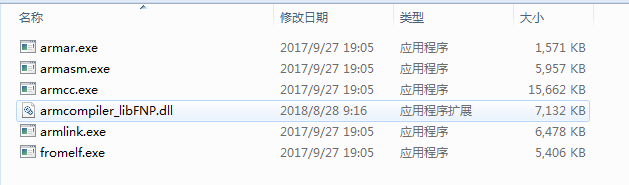
armar is used to package. o files into lib files, armasm compile assembly files, armcc compile c/c + + files, armlink link link object files, and from generate download format files. It converts them into hex files according to axf image files, and lists the number of errors and warnings in the compilation process. To call these compilation tools, you need to use the "command line prompt tool" of Windows. In order to make it easy for the command line to find these tools, we first add the directory of the tool chain to the environment variable of the system.
3. Open the command line of Windows, click the "Start Menu" of the system, enter "cmd" in the search box, and click "cmd.exe" in the search results to open the command line, as shown in the figure
Enter "from" in the pop-up command line window. If the help description of formelf is printed in the window, the path is normal and you can start the following work; If the message "neither internal name nor external command nor runnable program..." is prompted, it indicates that the path is wrong. Please reconfigure the environment variables and confirm that there is a compilation tool chain under the working directory.
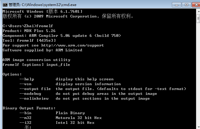
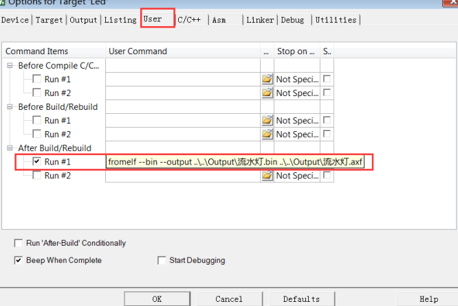
The essence of this process is to let the command line find the "from. Exe" program through the "PATH" PATH to run. By default, when running "from. Exe", it will output its own help information, which is the calling process of the tool chain. Keil essentially calls the tool chain, but it is integrated into a GUI (Interface), which is more user-friendly than the command line, After all, the above process of configuring environment variables has annoyed novices. Explain how the contents in this cmd box correspond to keil. From can generate hex and bin files based on axf files. Hex and bin files are the download file formats supported by most downloaders. For example, if we want to use from to generate bin files, we can add instructions to call from in the "option for target - > user" page of MDK, as shown in the following figure
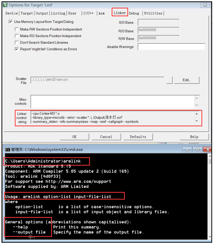
The configuration interface of linker is as follows:
So what's the use of these things? Take a look at this Code:
Reset_Handler   PROC
                EXPORT  Reset_Handler               [WEAK]
                IMPORT  SystemInit
                IMPORT  __main

                LDR     r0, =errorfunc
                BLX     r0
                LDR     r0, =__main
                BX      r0
                ENDP
Reset in startup code_ Handler code, you can see at a glance that this code is wrong. The errorfunc tion in red font is a non-existent function I deliberately filled in here. It will inevitably report an error when compiling. Let's see how the compiler reports an error?
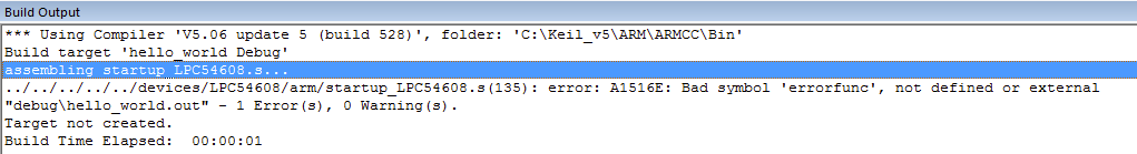
Focus on the part with blue shading on the way. Pay attention to the first word: assembling... Followed by an error message. Yes, this is an assembler error; Next, I will give an error in the code (I deleted a header file in main.c):
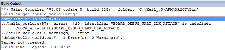
Look at the blue shading. Notice the first word: compiling... Followed by the error message. Yes, this is a compiler error. Different from the above, this is a compiler error. Let's look at the following error. The code is as follows
int main(void)
{
    char ch;

    /* Init board hardware. */
    /* attach 12 MHz clock to FLEXCOMM0 (debug console) */
    CLOCK_AttachClk(BOARD_DEBUG_UART_CLK_ATTACH);

    BOARD_InitPins();
    BOARD_BootClockFROHF48M();
    BOARD_InitDebugConsole();

    PRINTF("hello world.\r\n");

    while (1)
    {
        ch = errorfunc();
        PUTCHAR(ch);
    }
}
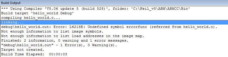
Look at the blue shading. Notice the first word: linking... Followed by an error message. This time it's a linker error!
People often say that the compiler reports errors. In fact, several different things report errors again. The compiler, assembler and linker will report errors. Then you may ask, what's the use of knowing this? Of course, it is useful. For example, the error reported by the assembler basically has nothing to do with the C language. It can be basically concluded that it is an assembly language syntax error or an assembly language error embedded in the C language (embedding assembly in C is a very effective programming means); If the linker reports an error, it has nothing to do with the C language syntax. It is not an error in your C syntax. It is likely that you called a nonexistent function or the linker script was written incorrectly, or used a nonexistent label Symbol, or did not contain the header file. h; Only when the compiler reports an error, there is always a problem with your c
4. Work report. map file
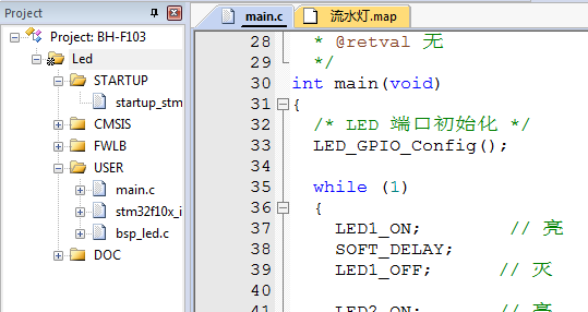
The really useful linker description file ". map" is very useful (after compiling the link, double-click the second folder under the project list to open the gray one)
". map" is definitely your "core employee" work report, and it is also the most complex one. It mainly contains cross link information. By viewing this file, you can understand the references between various symbols in the project and the detailed and summary information of Code, RO data, RW data and Zi data of the whole project. Its contents mainly include "cross file reference of section area", "deleting useless section area", "symbol image table", "storage image index" and "image component size".
Section Cross References

    startup_stm32f10x_hd.o(RESET) refers to startup_stm32f10x_hd.o(STACK) for __initial_sp
    startup_stm32f10x_hd.o(RESET) refers to startup_stm32f10x_hd.o(.text) for Reset_Handler
    startup_stm32f10x_hd.o(RESET) refers to stm32f10x_it.o(i.NMI_Handler) for NMI_Handler
    startup_stm32f10x_hd.o(RESET) refers to stm32f10x_it.o(i.HardFault_Handler) for HardFault_Handler
    startup_stm32f10x_hd.o(RESET) refers to stm32f10x_it.o(i.MemManage_Handler) for MemManage_Handler
    startup_stm32f10x_hd.o(RESET) refers to stm32f10x_it.o(i.BusFault_Handler) for BusFault_Handler
    startup_stm32f10x_hd.o(RESET) refers to stm32f10x_it.o(i.UsageFault_Handler) for UsageFault_Handler
    startup_stm32f10x_hd.o(RESET) refers to stm32f10x_it.o(i.SVC_Handler) for SVC_Handler
    startup_stm32f10x_hd.o(RESET) refers to stm32f10x_it.o(i.DebugMon_Handler) for DebugMon_Handler
    startup_stm32f10x_hd.o(RESET) refers to stm32f10x_it.o(i.PendSV_Handler) for PendSV_Handler
    ......(ellipsis)
In this section, the symbol references between *. o files are listed in detail. Since *. o files are generated after compiling asm or c/c + + source files, each file and the section sections in the file are independent of each other. The linker links them according to their mutual references. The link details are listed one by one in this "Section Cross References".
Explain line 3. Other lines have similar explanations. Line 3 describes startup_ The "_initial_sp" symbol (/ function) in the "RESET" section of the stm32f10x. O file refers to the "STACK" section (/ function) of the same file. These cross file reference symbols are actually function names and variable names in the source file.
Removing Unused input sections from the image.

    Removing startup_stm32f10x_hd.o(HEAP), (512 bytes).
    Removing core_cm3.o(.emb_text), (32 bytes).
    Removing system_stm32f10x.o(i.SystemCoreClockUpdate), (164 bytes).
    Removing system_stm32f10x.o(.data), (20 bytes).
    Removing misc.o(i.NVIC_Init), (112 bytes).
    Removing misc.o(i.NVIC_PriorityGroupConfig), (20 bytes).
    Removing misc.o(i.NVIC_SetVectorTable), (20 bytes).
    Removing misc.o(i.NVIC_SystemLPConfig), (32 bytes).
    Removing misc.o(i.SysTick_CLKSourceConfig), (40 bytes).
    Removing stm32f10x_adc.o(i.ADC_AnalogWatchdogCmd), (20 bytes).
    Removing stm32f10x_adc.o(i.ADC_AnalogWatchdogSingleChannelConfig), (16 bytes).
    Removing stm32f10x_adc.o(i.ADC_AnalogWatchdogThresholdsConfig), (6 bytes).
    Removing stm32f10x_adc.o(i.ADC_AutoInjectedConvCmd), (22 bytes)
    .......((omitted)
This section lists the unreferenced sections found in the project during the linking process. These unreferenced sections will be deleted (not added to the *. axf file, not deleted in the *. o file), which can prevent these useless data from occupying the program space. This part is done automatically by the compiler without human participation.
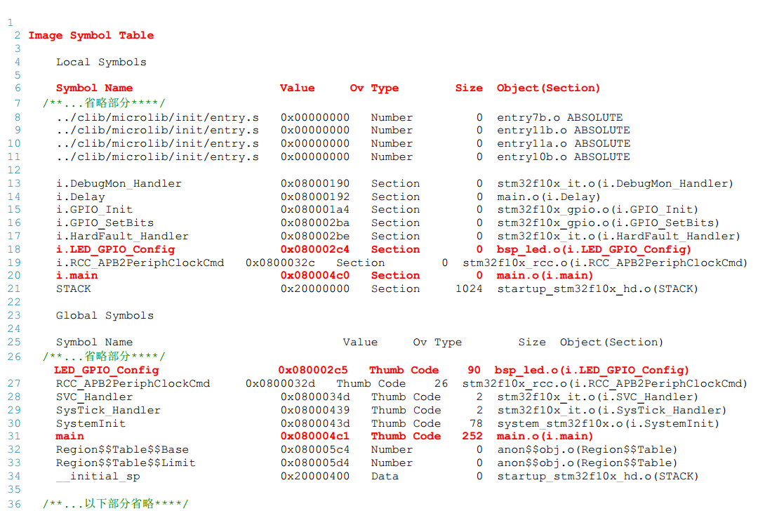
This table lists the specific address and occupied space of each referenced symbol in the memory. If we can find the LED_ GPIO_ The config symbol (0x080002c5) is stored at the address 0x080002c4. It belongs to the Thumb Code type, with a size of 90 bytes, and its section area is BSP_ I.led of LED. O file_ GPIO_ Config section.
Memory Map of the image

  Image Entry point : 0x08000131

  Load Region LR_IROM1 (Base: 0x08000000, Size: 0x000005d4, Max: 0x00080000, ABSOLUTE)

    Execution Region ER_IROM1 (Exec base: 0x08000000, Load base: 0x08000000, Size: 0x000005d4, Max: 0x00080000, ABSOLUTE)

    Exec Addr    Load Addr    Size         Type   Attr      Idx    E Section Name        Object

    0x08000000   0x08000000   0x00000130   Data   RO            3    RESET               startup_stm32f10x_hd.o
    0x08000130   0x08000130   0x00000000   Code   RO         3207  * .ARM.Collect$$$$00000000  mc_w.l(entry.o)
    0x08000130   0x08000130   0x00000004   Code   RO         3210    .ARM.Collect$$$$00000001  mc_w.l(entry2.o)
    0x08000134   0x08000134   0x00000004   Code   RO         3213    .ARM.Collect$$$$00000004  mc_w.l(entry5.o)

    ......

    0x080002c4   0x080002c4   0x00000060   Code   RO         3192    i.LED_GPIO_Config   bsp_led.o
    0x08000324   0x08000324   0x00000004   Code   RO         3132    i.MemManage_Handler  stm32f10x_it.o
    0x08000328   0x08000328   0x00000002   Code   RO         3133    i.NMI_Handler       stm32f10x_it.o
    0x0800032a   0x0800032a   0x00000002   Code   RO         3134    i.PendSV_Handler    stm32f10x_it.o

    ......


    Execution Region RW_IRAM1 (Exec base: 0x20000000, Load base: 0x080005d4, Size: 0x00000400, Max: 0x00010000, ABSOLUTE)

    Exec Addr    Load Addr    Size         Type   Attr      Idx    E Section Name        Object

    0x20000000        -       0x00000400   Zero   RW            1    STACK               startup_stm32f10x_hd.o
The storage image index of the project is divided into ER_IROM1 and RW_IRAM1, which respectively correspond to the space of FLASH and SRAM in STM32. Compared with the symbol image table, the unit described by this index table is the section area, and the main information described by it includes the type and attribute of the section area, so Code, RO data, RW data and Zi data can be distinguished.
From the table above, we can see i.led_ GPIO_ The config section is stored in the 0x080002c4 address of internal FLASH, with the size of 0x00000060, the type of Code and the attribute of RO. The STACK section (STACK space) of the program is stored in the 0x20000000 address of SRAM, with the size of 0x00000400, the type of Zero and the attribute of RW (i.e. RW data).
5. Image component size
The last part of the map file contains image component sizes, which is also the most frequently queried content.
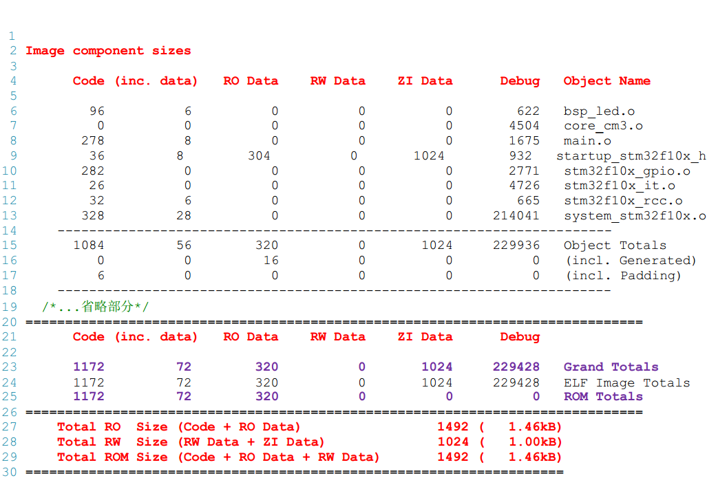
The last part lists the read-only data (RO), read-write data (RW), and the occupied ROM size. The read-only data size is 1492 bytes, which includes Code segment and RO data segment; The size of read-write data is 1024 bytes, which includes RW data and Zi data segments; The occupied ROM size is 1492 bytes. In addition to the Code section and RO data section, it also contains RW data that needs to be loaded from ROM to RAM during operation (RW data in this project is 0 bytes). In fact, in the map file, the storage space occupation of each function will be listed (symbol image table).
Summary: Based on the information of the entire map file, it can be analyzed that when the program is downloaded to the internal FLASH of STM32, the internal FLASH to be used is a space of 1492 bytes starting from the address 0x0800 0000; When the program is running, the internal SRAM to be used is a space of 1024 bytes starting from 0x20000000 address.