5.vins_estimator
Basically, most of the functions in VINS are under this package, including IMU data processing (front end), initialization (I think it may belong to front end), sliding window (back end), nonlinear optimization (back end), key frame selection (part of content) (front end). When I first saw it, I always had a question about why I put so much content in this node. In order to answer this question, first of all, we need to find out what are the specific contents of the vins_estimator, why there are these data structures / functions, and how they work.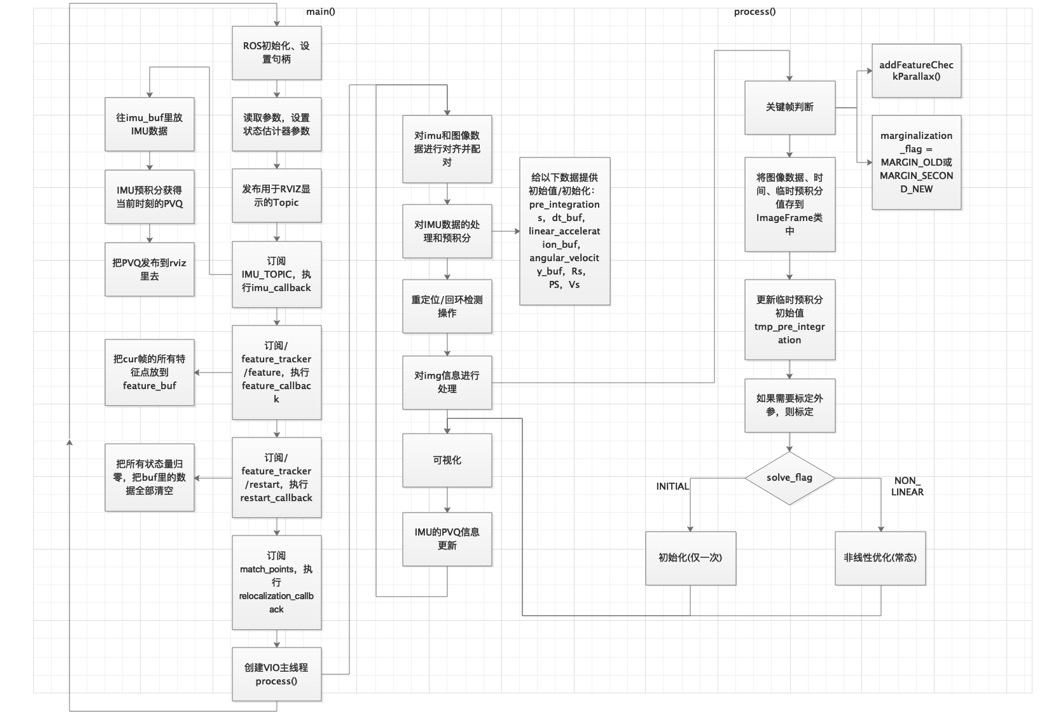
This package mainly includes the following files:
factor is mainly used for the definition of each parameter block and residual block in nonlinear optimization. VINS uses ceres, so this part needs to inherit and rewrite some state quantities and factors.
initial - mainly used for initialization. The initialization strategy adopted by VINS is to perform visual initialization of SfM first, and then loose coupling with IMU.
estimator.cpp - all the functions required by vins'estimator are put here, which is a huge work.
estimator_node.cpp -- the entry of vins_estimator, which is a ROS node, actually runs the cpp file.
Feature manager.cpp - responsible for managing all feature points in the sliding window.
parameters.cpp -- read parameters, which is an auxiliary function.
utility - there are functions and tick timers for visualization.
Then we should pay attention to the writing methods of CmakeLists.txt and package.xml files. These two files are also equivalent to a set of formulas. If you write them wrong, you cannot realize the normal ROS function.
5.1 estimator_node
5.1.1 main() main entrance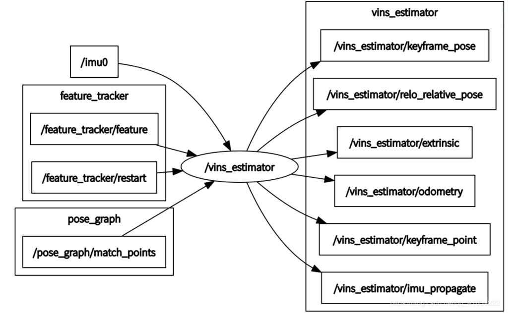
1. ROS initialization, setting handle
ros::init(argc, argv, "vins_estimator");
ros::NodeHandle n("~");
ros::console::set_logger_level(ROSCONSOLE_DEFAULT_NAME, ros::console::levels::Info);
2. Read parameters, set state estimator parameters
    readParameters(n);
    estimator.setParameter();
//This estimator.setParameter()Notice that it's in estimator.cpp Inside:
void Estimator::setParameter()
{
    for (int i = 0; i < NUM_OF_CAM; i++)
    {
        tic[i] = TIC[i];
        ric[i] = RIC[i];
    }
    f_manager.setRic(ric);
    ProjectionFactor::sqrt_info = FOCAL_LENGTH / 1.5 * Matrix2d::Identity();
    ProjectionTdFactor::sqrt_info = FOCAL_LENGTH / 1.5 * Matrix2d::Identity();
    td = TD;
}
It reads the information matrix of the external parameters of rotation / translation from each camera to IMU coordinate system and the re projection error part of nonlinear optimization.
3. Issue the Topic for RVIZ display. For details of this module, please refer to input and output
registerPub(n);
This function is defined in utility/visualization.cpp: void registerpub (ROS:: nodehandle & n).
4. Subscribe to IMU topic and execute IMU callback
ros::Subscriber sub_imu = n.subscribe(IMU_TOPIC, 2000, imu_callback, ros::TransportHints().tcpNoDelay());
This callback function is important, as shown in the following code:
void imu_callback(const sensor_msgs::ImuConstPtr &imu_msg)
{
    if (imu_msg->header.stamp.toSec() <= last_imu_t)
    {
        ROS_WARN("imu message in disorder!");
        return;
    }
    last_imu_t = imu_msg->header.stamp.toSec();
    m_buf.lock();
    imu_buf.push(imu_msg);
    m_buf.unlock();
    con.notify_one();
    last_imu_t = imu_msg->header.stamp.toSec();
    {
        std::lock_guard<std::mutex> lg(m_state);
        predict(imu_msg);
        std_msgs::Header header = imu_msg->header;
        header.frame_id = "world";
        if (estimator.solver_flag == Estimator::SolverFlag::NON_LINEAR)
            pubLatestOdometry(tmp_P, tmp_Q, tmp_V, header);
    }
}
IMU call has done three things,
The first thing is to put the IMU data in the IMU buf and cache it;
The second thing is that IMU pre integration obtains PVQ at the current time, see 4.1.2;
The third thing is that if you are currently in the stage of nonlinear optimization, you need to publish the PVQ calculated from the second thing to rviz. See the pubLatestOdometry() function of utility/visualization.cpp.
In this function, lock operation occurs for the first time, because this program is multithreaded, and thread safety needs to be considered. The operation of IMU buf is a producer consumer model, which can not be interrupted when it is added and read, and must be locked to ensure data safety. There are lock operations in multiple places in the following parts.
Several new data structures appear in this part, which are explained as follows:
Data structure:
TMP? Q, TMP? P, TMP? V: PVQ at the current time
 header: current time stamp
5. Subscribe to / feature > tracker / feature, execute feature > callback
ros::Subscriber sub_image = n.subscribe("/feature_tracker/feature", 2000, feature_callback);
This part receives the information of all feature points in cur frame published by feature tracker node, as shown in 3.3.6.
Only one thing feature callback does is to put all feature points of cur frame into feature buf, which also needs to be locked. Note that all feature points of the cur frame are integrated in one data, that is, sensor ﹣ msgs:: pointcloudconstptptr & feature ﹣ MSG.
6. Subscribe to / feature ﹣ tracker / restart, and execute restart ﹣ callback
ros::Subscriber sub_restart = n.subscribe("/feature_tracker/restart", 2000, restart_callback);
Restart "callback does one thing, which is to reset all state variables to zero and clear all data in buf.
7. Subscribe to / post graph / match points and execute relocation callback
ros::Subscriber sub_relo_points = n.subscribe("/pose_graph/match_points", 2000, relocalization_callback);
8. Create VIO main thread process()(VINS core! )
std::thread measurement_process{process};
This part is the most important part, including most of the content and the most difficult content of VINS.
5.1.2 process() main thread
1. Align and pair imu and image data
I've been stuck with this part for a long time, and I've finally figured it out.
 std::vector<std::pair<std::vector<sensor_msgs::ImuConstPtr>, sensor_msgs::PointCloudConstPtr>> measurements;

        std::unique_lock<std::mutex> lk(m_buf);
        con.wait(lk, [&]{return (measurements = getMeasurements()).size() != 0; });
        lk.unlock();
First up is a very complex data structure measurement! Let's explain a wave here.
Data structure: measurements
 1. First of all, measures himself is a vector;
2. For each measurement in measurement, it is composed of two parts;
3. The first part is a vector composed of sensor_msgs::ImuConstPtr;
4. In the second part, a sensor_msgs:: pointcloudconstpttr;
5. See section 3.1-6 for these two sensors.
6. Why pairing like this (a PointCloudConstPtr with several imuconstptrs)? Because the frequency of IMU is higher than that of visual frame, it is necessary to match a visual frame with the data of previous IMU frames.
Container measurements is available. Next, the data of matching IMU and visual frame is put into the container. The pairing process also needs to be locked, and it is a conditional lock. The author uses a lambda expression here, that is to say, when the part in return is false, keep the lock state and continue to pair the data; if the part in return is true, it means that the pairing is completed, the lock is released and the measurements are completed for subsequent use.
Next, analyze the specific functions of measures():
//The function is to match the image frame with the corresponding IMU data, and the time of the IMU data is in front of the image frame
std::vector<std::pair<std::vector<sensor_msgs::ImuConstPtr>, sensor_msgs::PointCloudConstPtr>>
getMeasurements()
{
    std::vector<std::pair<std::vector<sensor_msgs::ImuConstPtr>, sensor_msgs::PointCloudConstPtr>> measurements;
    while (true)
    {   //Boundary judgment: data acquisition is completed, indicating that pairing is completed
        if (imu_buf.empty() || feature_buf.empty())
            return measurements;
//Boundary judgment: the time stamps of all data in the IMU buf are earlier than the time stamps of the first frame of the img buf, indicating the lack of IMU data and the need to wait for IMU data
        if (!(imu_buf.back()->header.stamp.toSec() > feature_buf.front()->header.stamp.toSec() + estimator.td))
        {
            sum_of_wait++;//Count the number of waits
            return measurements;
        }

        //Boundary judgment: the time of the first data of IMU is longer than that of the first image feature data (indicating the number of image frames)
        if (!(imu_buf.front()->header.stamp.toSec() < feature_buf.front()->header.stamp.toSec() + estimator.td))
        {
            feature_buf.pop();
            continue;
        }
        //Core operation: load visual frame information
        sensor_msgs::PointCloudConstPtr img_msg = feature_buf.front();
        feature_buf.pop();
        //Core operation: transfer to IMU information
        std::vector<sensor_msgs::ImuConstPtr> IMUs;
        while (imu_buf.front()->header.stamp.toSec() < img_msg->header.stamp.toSec() + estimator.td)
        {
            IMUs.emplace_back(imu_buf.front());
            imu_buf.pop();
        }
        //Note: put the last IMU frame back in the IMU buf
        //Reason: IMU information of the last frame is shared by two adjacent visual frames
        IMUs.emplace_back(imu_buf.front());

        measurements.emplace_back(IMUs, img_msg);
    }
    return measurements;
}
2. Processing of IMU data
m_estimator.lock();
for (auto &measurement : measurements)//2. Operate on each measurement (IMUs,IMG) combination in measurements
{//2.1. For each IMU? MSG in measurement, calculate dt and execute processIMU()
    auto img_msg = measurement.second;
    double dx = 0, dy = 0, dz = 0, rx = 0, ry = 0, rz = 0;

    for (auto &imu_msg : measurement.first)
    {
        double t = imu_msg->header.stamp.toSec();
        double img_t = img_msg->header.stamp.toSec() + estimator.td;//Time difference from synchronous calibration of camera and IMU
        //In most cases, the time stamp of IMU is earlier than that of img, so the data of IMU can be selected directly
        if (t <= img_t)  //http://wiki.ros.org/sensor_msgs
        {
            if (current_time < 0)
                current_time = t;
            double dt = t - current_time;
            ROS_ASSERT(dt >= 0);
            current_time = t;
            dx = imu_msg->linear_acceleration.x;
            dy = imu_msg->linear_acceleration.y;
            dz = imu_msg->linear_acceleration.z;
            rx = imu_msg->angular_velocity.x;
            ry = imu_msg->angular_velocity.y;
            rz = imu_msg->angular_velocity.z;
  //Two things are done here. IMU roughly pre integrates and then passes the value to a new IntegrationBase object
            estimator.processIMU(dt, Vector3d(dx, dy, dz), Vector3d(rx, ry, rz));//Perform IMU pre integration
        }

        //For the IMU data in the boundary position, it is shared by two adjacent frames, and has a greater impact on the previous frame. Here, the data is allocated linearly
        else//Each first IMU ﹣ MSG larger than the image frame time stamp is shared by two image frames (less occurrences)
        {
            double dt_1 = img_t - current_time; //current_time < img_time < t
            double dt_2 = t - img_t;
            current_time = img_t;
            ROS_ASSERT(dt_1 >= 0);
            ROS_ASSERT(dt_2 >= 0);
            ROS_ASSERT(dt_1 + dt_2 > 0);
			 //The following operations are actually simple linear assignments
            double w1 = dt_2 / (dt_1 + dt_2);
            double w2 = dt_1 / (dt_1 + dt_2);
            dx = w1 * dx + w2 * imu_msg->linear_acceleration.x;
            dy = w1 * dy + w2 * imu_msg->linear_acceleration.y;
            dz = w1 * dz + w2 * imu_msg->linear_acceleration.z;
            rx = w1 * rx + w2 * imu_msg->angular_velocity.x;
            ry = w1 * ry + w2 * imu_msg->angular_velocity.y;
            rz = w1 * rz + w2 * imu_msg->angular_velocity.z;
            estimator.processIMU(dt_1, Vector3d(dx, dy, dz), Vector3d(rx, ry, rz));
        }
This if else operation skill is worth learning! The core code of this part is processIMU(), which is in estimator.cpp, and its function is IMU pre integration, corresponding to the content of 4.1.2.
void Estimator::processIMU(double dt, const Vector3d &linear_acceleration, const Vector3d &angular_velocity)
{
  /*The purpose of this section is to provide initial value / initialization for the following data:
   *
   *pre_integrations[frame_count]
   *dt_buf[frame_count]
   *linear_acceleration_buf[frame_count]
   *angular_velocity_buf[frame_count]
   *Rs[frame_count]
   *PS[frame_count]
   *Vs[frame_count]
   *
   * TODO For the update of frame ﹣ count, you can only see it in solver ﹣ flag = = initial in process ﹣ img?
   *
   */
    //Boundary judgment: if the current frame is not the first IMU, then it is regarded as the first IMU, and its value is taken as the initial value
    if (!first_imu)//force to be first_IMU
    {
        first_imu = true;
        acc_0 = linear_acceleration;
        gyr_0 = angular_velocity;
    }
    //Boundary judgment: if the integration base is not constructed in the current IMU frame, one will be constructed, which will be used later
    if (!pre_integrations[frame_count])
    {
        pre_integrations[frame_count] = new IntegrationBase{acc_0, gyr_0, Bas[frame_count], Bgs[frame_count]};
    }
    //Core operation
    if (frame_count != 0)
    {
        pre_integrations[frame_count]->push_back(dt, linear_acceleration, angular_velocity);
        //if(solver_flag != NON_LINEAR)
            tmp_pre_integration->push_back(dt, linear_acceleration, angular_velocity);
        dt_buf[frame_count].push_back(dt);
        linear_acceleration_buf[frame_count].push_back(linear_acceleration);
        angular_velocity_buf[frame_count].push_back(angular_velocity);

        int j = frame_count;

        //Note that this operation on j seems to be anti intelligent, because the value of j time copies the value of j-1 time!!
        //The first use is actually the value of j-1 time, so it doesn't matter to write j-1 in these places!
        //noise is zero mean Gauss, ignored here
        //TODO changes j to j-1, and the effect is the same
        Vector3d un_acc_0 = Rs[j] * (acc_0 - Bas[j]) - g;//world
        //The following is the propagation mode of median integral, noise is ignored
        //TODO changes j to j-1, and the effect is the same
        Vector3d un_gyr = 0.5 * (gyr_0 + angular_velocity) - Bgs[j];
        //PPT 1-27
        Rs[j] *= Utility::deltaQ(un_gyr * dt).toRotationMatrix();
        Vector3d un_acc_1 = Rs[j] * (linear_acceleration - Bas[j]) - g;
        Vector3d un_acc = 0.5 * (un_acc_0 + un_acc_1);
        Ps[j] += dt * Vs[j] + 0.5 * dt * dt * un_acc;
        Vs[j] += dt * un_acc;
    }
    //Data transfer
    acc_0 = linear_acceleration;
    gyr_0 = angular_velocity;
}
For the pre integration part of IMU, see 4.1.2. Here are several new data structures, which are analyzed as follows:
Data structure:
1. RS [frame & count], PS [frame & count], vs [frame & count]: PVQ from IMU system to world system. The data is obtained by IMU pre integration. Currently, the value stored here is not corrected by bias.
2. frame_count: this value makes me wonder. It only has + + operation in processImage(), and no static keyword is added when the estimator.hpp is declared. It is declared in the h file and initialized in the cpp file. We need to pay more attention to it later.
3. DT buf, linear acceleration buf, angular velocity buf: cache of frames and IMU measurements, and they are aligned.
3. Pre ﹣ integrations [frame ﹣ count], an example of integration base, is defined in factor / integration ﹣ base. H. it stores all the values related to IMU pre integration in frame ﹣ count frame, including F matrix, Q matrix, J matrix, etc.
3. Relocation / loopback detection operation
Return to the process() function of estimator_node.cpp. The next code is to take out the last relocation frame in relo buf, take out the information in it and execute setReloFrame()
        // set relocalization frame
        sensor_msgs::PointCloudConstPtr relo_msg = NULL;
   //2.2. Take out the last relocation frame in relo buf, take out the information in it and execute setReloFrame()
        while (!relo_buf.empty())
        {
            relo_msg = relo_buf.front();
            relo_buf.pop();
        }

        if (relo_msg != NULL)
        {
            vector<Vector3d> match_points;
            double frame_stamp = relo_msg->header.stamp.toSec();
            for (unsigned int i = 0; i < relo_msg->points.size(); i++)
            {
                Vector3d u_v_id;
                u_v_id.x() = relo_msg->points[i].x;
                u_v_id.y() = relo_msg->points[i].y;
                u_v_id.z() = relo_msg->points[i].z;
                match_points.push_back(u_v_id);
            }
            Vector3d relo_t(relo_msg->channels[0].values[0], relo_msg->channels[0].values[1], relo_msg->channels[0].values[2]);
            Quaterniond relo_q(relo_msg->channels[0].values[3], relo_msg->channels[0].values[4], relo_msg->channels[0].values[5], relo_msg->channels[0].values[6]);
            Matrix3d relo_r = relo_q.toRotationMatrix();
            int frame_index;
            frame_index = relo_msg->channels[0].values[7];
            estimator.setReloFrame(frame_stamp, frame_index, match_points, relo_t, relo_r);//Set relocation frame
        }
4. Processing img information (core! )
(1) At the beginning, a new data structure is defined, which is explained as follows:
map<int, vector<pair<int, Eigen::Matrix<double, 7, 1>>>> image;
Data structure: Map < int, vector < pair < int, eigen:: matrix < double, 7, 1 > > > Image
 1. Although it is called image, the information stored in this container is the information of each feature point!
2. The index value is feature ID;
3. The value value is a vector. If the system is multi-purpose, the same feature point will have different observation information under different cameras. Then this vector is to store the information of a feature point on all cameras. For vins mono, value is not a vector, just a pair, but it can.
4. Next, look at each pair in the vector. int corresponds to camera_id, which tells us which camera the current feature points are obtained from.
5. Matrix < double, 7,1 > is a 7-dimensional vector, which successively stores the normalized coordinates, pixel coordinates and pixel motion speed of the feature points of the current feature ID in the camera of the camera ID. all these information are obtained in feature tracker node.cpp.
(2) After the data structure is defined, the next step is to put data into the container.
//To traverse the normalized coordinates of each feature point in img
            for (unsigned int i = 0; i < img_msg->points.size(); i++)
            {
                //Extract the img information and put it in the image container. Through this, you can understand what is in the img information
                int v = img_msg->channels[0].values[i] + 0.5; //channels[0].values[i]==id_of_point
               //hash
                int feature_id = v / NUM_OF_CAM;
                int camera_id = v % NUM_OF_CAM;

                double x = img_msg->points[i].x;
                double y = img_msg->points[i].y;
                double z = img_msg->points[i].z;
                double p_u = img_msg->channels[1].values[i];
                double p_v = img_msg->channels[2].values[i];
                double velocity_x = img_msg->channels[3].values[i];
                double velocity_y = img_msg->channels[4].values[i];

                Eigen::Matrix<double, 7, 1> xyz_uv_velocity;
                xyz_uv_velocity << x, y, z, p_u, p_v, velocity_x, velocity_y;
                image[feature_id].emplace_back(camera_id,  xyz_uv_velocity);
            }
(3) Processing image processImage() (core! )
There are many contents in this part, which will be explained layer by layer in Section 5.2! The initialization of vision and IMU and the tight coupling of nonlinear optimization are realized here.
estimator.processImage(image, img_msg->header);//Image frame processing: initialization, tight coupling nonlinear optimization
5. Visualization
Release odometer information, key pose, camera pose, point cloud and TF relationship to RVIZ. These functions are defined in the utility/visualization.cpp, and are all ROS related codes.
pubOdometry(estimator, header);
pubKeyPoses(estimator, header);
pubCameraPose(estimator, header);
pubPointCloud(estimator, header);
pubTF(estimator, header);
pubKeyframe(estimator);
if (relo_msg != NULL)
    pubRelocalization(estimator);
6. PVQ information update of IMU
Update the IMU parameters [P,Q,V,ba,bg,a,g]. Lock it and pay attention to thread safety. The corresponding knowledge point here is the last formula of 4.1.1.
m_buf.lock();
m_state.lock();
if (estimator.solver_flag == Estimator::SolverFlag::NON_LINEAR)
    update();
m_state.unlock();
m_buf.unlock();
The content of update() is as follows:
void update()//This function is only called in process() when nonlinear optimization is performed
{//1. The imu update term [P,Q,V,ba,bg,a,g] of the last image frame in the sliding window is obtained from the estimator
    TicToc t_predict;
    latest_time = current_time;
    tmp_P = estimator.Ps[WINDOW_SIZE];
    tmp_Q = estimator.Rs[WINDOW_SIZE];
    tmp_V = estimator.Vs[WINDOW_SIZE];
    tmp_Ba = estimator.Bas[WINDOW_SIZE];
    tmp_Bg = estimator.Bgs[WINDOW_SIZE];
    acc_0 = estimator.acc_0;
    gyr_0 = estimator.gyr_0;
//2. PVQ recursion of the remaining imu MSG in the imu buf (because the frequency of the imu is much higher than that of the image, after getMeasurements() aligns the image with the time of the imu, there will be imu data in the imu buf)
    queue<sensor_msgs::ImuConstPtr> tmp_imu_buf = imu_buf;
    for (sensor_msgs::ImuConstPtr tmp_imu_msg; !tmp_imu_buf.empty(); tmp_imu_buf.pop())
        predict(tmp_imu_buf.front());
}
Here's a question. Why update()?
Because after a process() loop, the current PVQ state is different from the beginning of the loop. So we need to update the current PVQ status, i.e. TMP x, according to the current data. Again, lock it.
5.2 processing image ()
This function is in estimator.cpp. First look at the function name. The parameters it passes in are all the feature points on the current frame and the timestamp of the current frame.
void Estimator::processImage(const map<int, vector<pair<int, Eigen::Matrix<double, 7, 1>>>> &image, const std_msgs::Header &header)
1. Key frame judgment
The strategy adopted by VINS sliding window is to determine whether the current frame is a key frame. If it is a key frame, marg will drop the oldest frame when sliding window; if it is not a key frame, marg will drop the last frame.
//true: the previous frame is a key frame, marg_old; false: the previous frame is not a key frame marg_second_new
//Todo frame? Count refers to the next new frame or the latest frame?
if (f_manager.addFeatureCheckParallax(frame_count, image, td))
    marginalization_flag = MARGIN_OLD;
else
    marginalization_flag = MARGIN_SECOND_NEW;
Here comes a new data structure, f'u manager, and a new function, addfeaturecheckparallelax().
Data structure: F & U Manager
 F? Manager is an object of FeatureManager. It is defined in utility / feature & manager. H. Three classes are defined in this h file, which is represented by a god map of Cui Shen as follows:
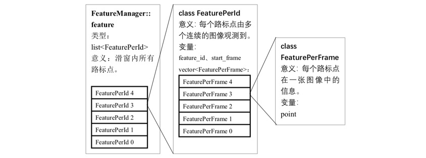
F manager can be seen as a container for storing all feature point information in the sliding window, the most critical part of which is list < FeaturePerId > feature. Each feature point can be regarded as a FeaturePerId object, which stores all the information of a feature point in the sliding window, and the most critical part is vector < feature per frame > feature_per_frame. The information of a feature point in a frame can be regarded as the object of a FeaturePerFrame. It stores the information of a feature point in a frame in the sliding window, including normalized coordinates, pixel coordinates, pixel speed, etc.
There are three layers of dolls.
Next, let's look at the logic in the addfeaturecheckparallelax() function, which is defined in feature_manager.cpp.
//Key frame judgment
bool FeatureManager::addFeatureCheckParallax(int frame_count, const map<int, vector<pair<int, Eigen::Matrix<double, 7, 1>>>> &image, double td)
{
    ROS_DEBUG("input feature: %d", (int)image.size());
    ROS_DEBUG("num of feature: %d", getFeatureCount());
    //Total parallelism
    double parallax_sum = 0;
    //Parallel feature points
    int parallax_num = 0;
    //Count how many feature points in the sliding window continue to be tracked in the current frame
    last_track_num = 0;

    //Traverse every feature point of the current frame
    for (auto &id_pts : image)
    {
        //Encapsulate the current feature point as a FeaturePerFrame object
        FeaturePerFrame f_per_fra(id_pts.second[0].second, td);
        //Get the feature ID of the current frame
        int feature_id = id_pts.first;
        //Among all feature points of sliding window, see if you can find the current feature point
        auto it = find_if(feature.begin(), feature.end(), [feature_id](const FeaturePerId &it)
                          {//It is a predicate judgment version of find. It uses the predicate that returns Boolean value to judge pred and checks every element on the iterator interval [first, last]. If iterator meets pred(*iter) == true, it means to find the element and return iterator value iter; if no meta element is found, it returns last.
            return it.feature_id == feature_id;
                          });
        //If the feature point is a new feature (not found in the feature point Library), then add it to the feature point Library of the sliding window
        if (it == feature.end())
        {
            feature.push_back(FeaturePerId(feature_id, frame_count));
            feature.back().feature_per_frame.push_back(f_per_fra);
        }
        //If this feature has been observed in the sliding window, the data of this feature point in the current frame will be supplemented, and the common view statistics will be + 1
        else if (it->feature_id == feature_id)
        {
            it->feature_per_frame.push_back(f_per_fra);
            last_track_num++;
        }
    }
    //If the total number of frames is 2, or the total view point is less than 20, then the next new frame is the key frame, marg ﹤ old
    if (frame_count < 2 || last_track_num < 20)
        return true;
    //Traverse every feature point in the sliding window
    for (auto &it_per_id : feature)
    {   //If the current feature point appears before the current frame -2 and at least the current frame -1, it is a parallel feature point
        if (it_per_id.start_frame <= frame_count - 2 &&
            it_per_id.start_frame + int(it_per_id.feature_per_frame.size()) - 1 >= frame_count - 1)
        {
            parallax_sum += compensatedParallax2(it_per_id, frame_count);
            parallax_num++;//Parallel feature points
        }
    }

    if (parallax_num == 0)//Judgment standard 1: the number of parallel feature points is 0
    { return true; }
    else//Judgment standard 2: average parallelism less than threshold
    { return parallax_sum / parallax_num >= MIN_PARALLAX; }
}
This part of the code is completely reflected in part IV.A of Qin Tong. In this part, Qin Shen wrote two key frame judgment indicators, the first is "the average parallel attack from the previous keyframe", which corresponds to the parallel_num and parallel_sum / parallel_num in the code; the second is "If the number of tracked features goes below a certain threshold, we treat this frame as a new keyframe ", which corresponds to last_track_num in the code. Note that another function in this section is compensatedparallelax2 (), which is used to calculate the parallax of the current feature point.
2. Save image data, time and temporary pre integration value into image frame class
ImageFrame imageframe(image, header.stamp.toSec());
imageframe.pre_integration = tmp_pre_integration;
all_image_frame.insert(make_pair(header.stamp.toSec(), imageframe));
A new data structure appears here, which is analyzed as follows:
Data structure: ImageFrame imageframe
 Imageframe is an instance of imageframe, defined in initial / initial "alignment. H. As the name implies, it is a data structure used to fuse IMU and visual information, including all information of a frame: pose, feature point information, pre integration information, whether it is a key frame, etc.
3. Update the initial value of temporary pre integration
tmp_pre_integration = new IntegrationBase{acc_0, gyr_0, Bas[frame_count], Bgs[frame_count]};
4. If external parameters need to be calibrated, calibrate
if(ESTIMATE_EXTRINSIC == 2)////Calibrate if there is no external parameter
{
    ROS_INFO("calibrating extrinsic param, rotation movement is needed");
    if (frame_count != 0)
    {
        vector<pair<Vector3d, Vector3d>> corres = f_manager.getCorresponding(frame_count - 1, frame_count);
        Matrix3d calib_ric;
        if (initial_ex_rotation.CalibrationExRotation(corres, pre_integrations[frame_count]->delta_q, calib_ric))
        {
            ROS_WARN("initial extrinsic rotation calib success");
            ROS_WARN_STREAM("initial extrinsic rotation: " << endl << calib_ric);
            ric[0] = calib_ric;
            RIC[0] = calib_ric;
            ESTIMATE_EXTRINSIC = 1;
        }
    }
}
5. Initialization
This is an important module, as described in the next chapter. Generally, initialization is only carried out once.
6. Nonlinear optimization
This is an important module, as described in the next chapter. The general nonlinear optimization is a part of the VINS system which has to be cyclic in the stable state.

