1, Basic principles
eNSP(Enterprise Network Simulation Platform) is a scalable and graphical network simulation tool platform provided by Huawei. It mainly carries out software simulation for enterprise network routers and switches, presents real equipment scenes, and supports large-scale network simulation, Users only need to configure network topology and devices to realize network protocol simulation and conduct packet capture analysis in conjunction with Wireshark.
NAT (Network Address Translation) is used for some hosts in the private network to access the Internet with the help of external routing equipment when they have been assigned to the local private IP. NAT can be implemented in three ways: Static Nat, Dynamic Nat and port multiplexing OverLoad.
The purpose of this experiment is to master the differences between NAT and NAPT protocols and the similarities and differences of packet generation at the network layer, such as circular allocation and redistribution of external addresses, change of packet header identification of the same IP, change of port number, etc.
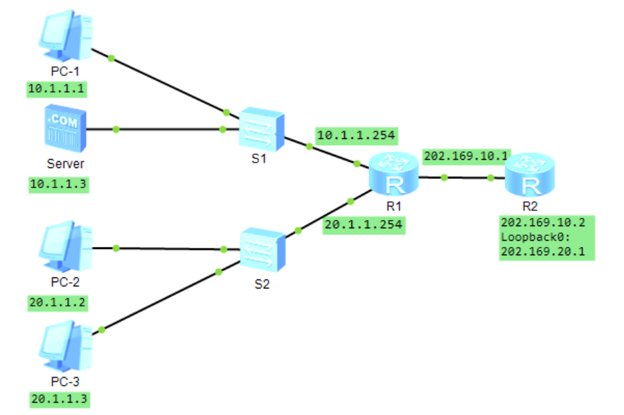
2, NAT protocol simulation topology
3, R1,R2 configuration and related command interpretation
1.R1 configuration information
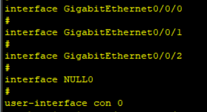
1.1 enter the system view and view the configuration information
system #Enter system view
display current-configuration #View configuration information
sysname R1
From the configuration information, you can see that the IP addresses of 0 / 0 / 0, 0 / 0 / 1, 0 / 0 / 2 and the default interface NULL0 are not configured at this time.
1.2 configure access control information and NAT address block
acl number 2001
rule 5 permit source 20.1.1.0 0.0.0.255 #Allow IP of 20.1.1.0 - 20.1.1.255 to pass through the network
nat address-group 1 202.169.10.50 202.169.10.60 #The external public network IP of the NAT router is 202.169.10.50-202.169.10.60
1.3 configure 0 / 0 / 0 interface
0 / 0 / 0 port is the external interface in the NAT router, and its configuration is more complex than 0 / 0 / 1, 0 / 0 / 2 and NULL0.
interface GigabitEthernet0/0/0
ip address 202.169.10.1 255.255.255.0  #Assign IP to port 0 / 0 / 0

arp-proxy enable #Open arp protocol permissions

nat static global 202.169.10.5 inside 10.1.1.1 netmask 255.255.255.255 #202.169.10.5 static binding to 10.1.1.1

nat outbound 2001 address-group 1 no-pat	# Bind acl 2001 and address block, nat dynamically assigns IP address to acl 2001, and prohibits port multiplexing
1.4 configure 0/0/1,0/0/2.NULL0 default interface and return
interface GigabitEthernet0/0/1
ip address 10.1.1.254 255.255.255.0

interface GigabitEthernet0/0/2
ip address 20.1.1.254 255.255.255.0

interface NULL0
ip route-static 0.0.0.0 0.0.0.0 202.169.10.2 #Configure the default address, that is, the default route
return
2.R2 configuration information
system
sysname R2 #Rename to R2

#Configure 0 / 0 / 0 interface and loopback address
interface GigabitEthernet0/0/0
ip address 202.169.10.2 255.255.255.0

interface LoopBack0
ip address 202.169.20.1 255.255.255.0
return
3. Configuration information of PC-1, PC-2, PC-3 and server
PC-1
IP:10.1.1.1
 Subnet mask:255.255.255.0
 gateway:10.1.1.254

PC-2
IP:20.1.1.2
 Subnet mask:255.255.255.0
 gateway:20.1.1.254

PC-3
IP:20.1.1.3
 Subnet mask: 255.255.255.0
 gateway:20.1.1.254

Server
IP:10.1.1.3
 gateway:10.1.1.254
4, Experimental phenomenon
When no pat is set:
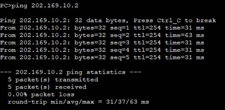
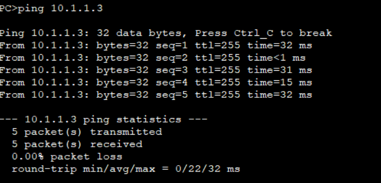
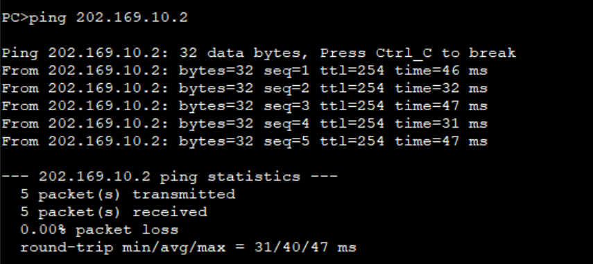
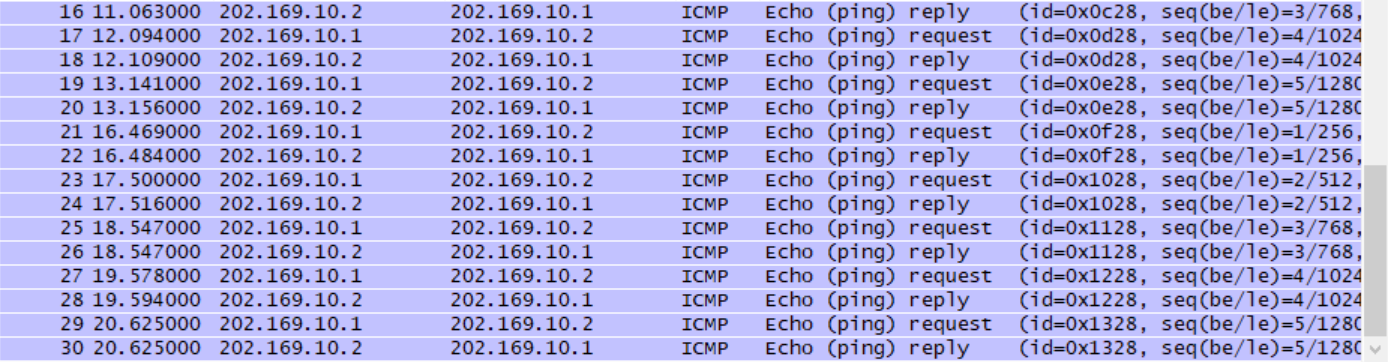
PC-1 access R2
PC-1 access Server
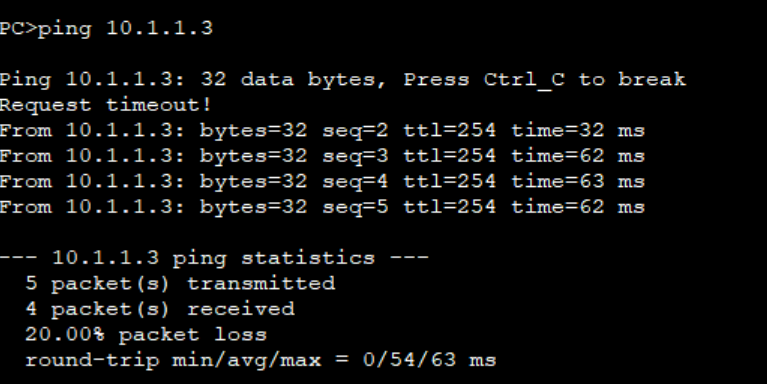
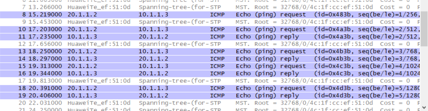
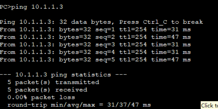
PC-2 access R2
PC-2 access Server
Set port multiplexing for R1:
interface GigabitEthernet0/0/0
undo nat outbound 2001 address-group 1 no-pat
nat outbound 2001		# Enable pat
When port multiplexing is set:
PC-1 access R2
 PC-1 access Server
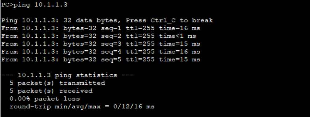
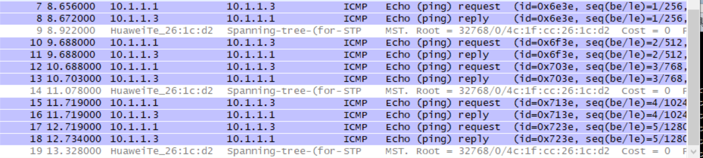
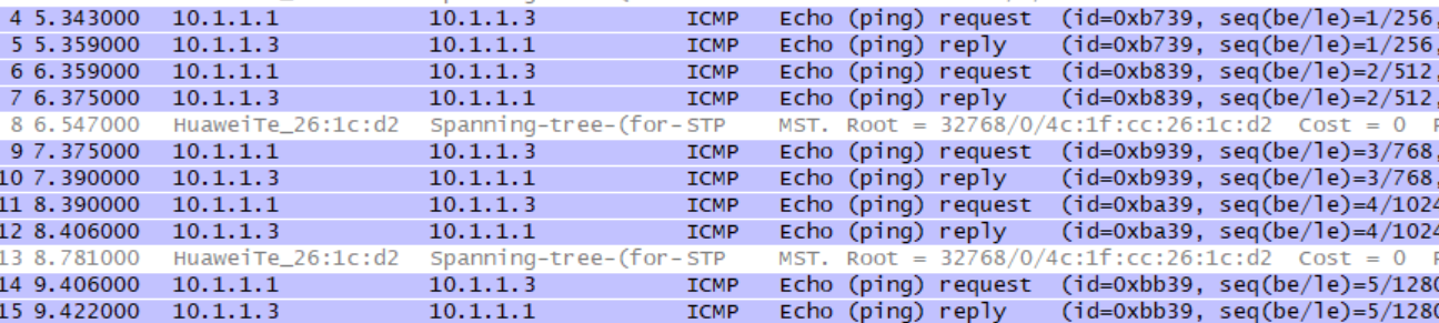
It can be seen that NAT is the same as NAPT when PC-1 accesses R2 and Server. This is because the IP address of PC-1 is statically mapped.
PC-2 access R2
PC-2 access Server
5, Result analysis
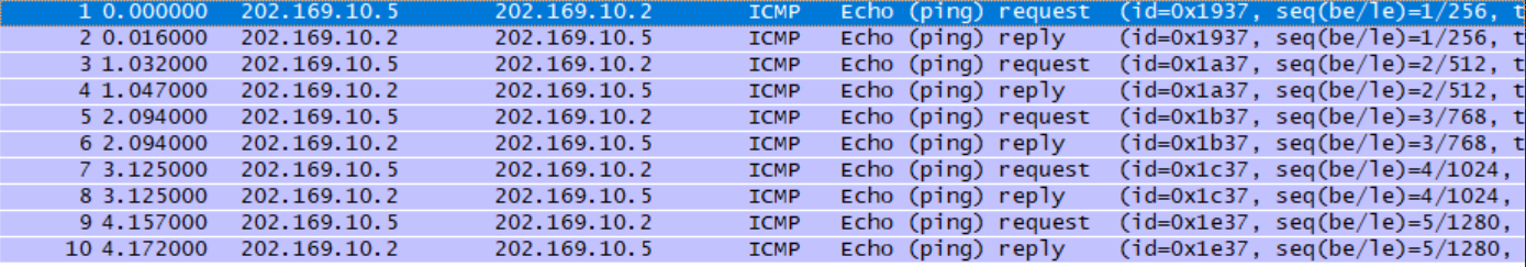
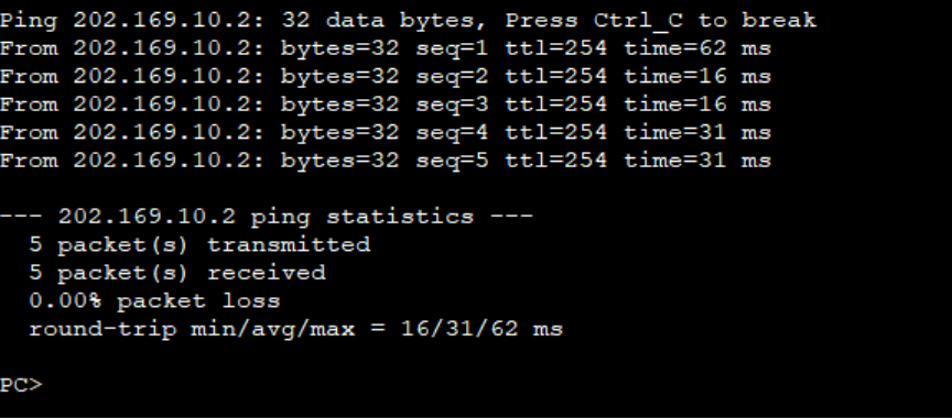
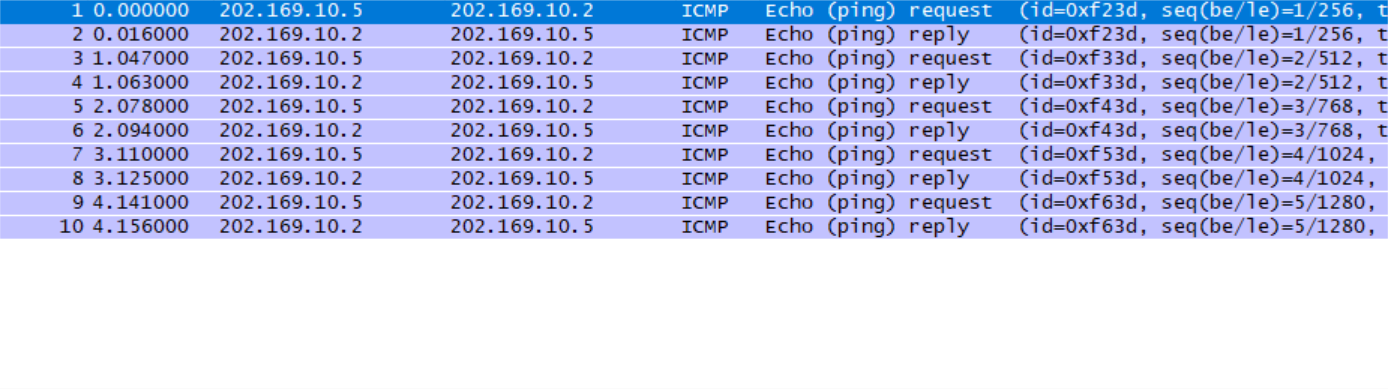
From PC-1 accessing R2 and Server, it can be seen that when Static Nat is used, its intranet IP and extranet are always bound.
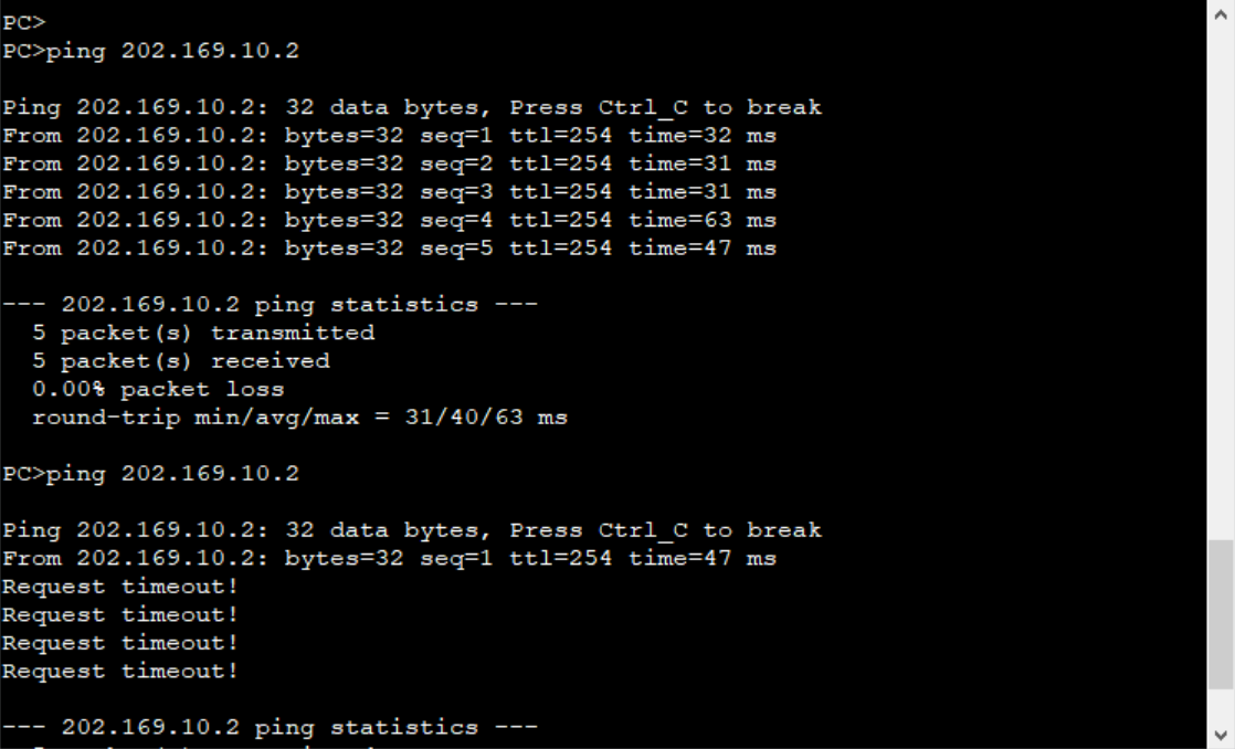
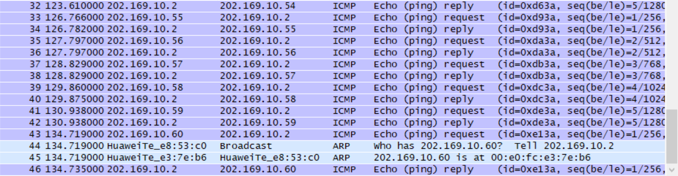
Dynamic Nat will be allocated circularly according to the IP in the allocated address pool, but after 60, because the IP address has not been recovered at this time, a request timeout appears. In other words, when dynamically allocating the address pool, the IP address has a certain recovery time. After using the public IP, it needs to wait for a period of recovery before it can be used again.

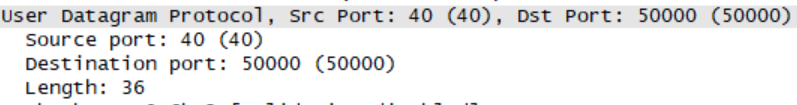
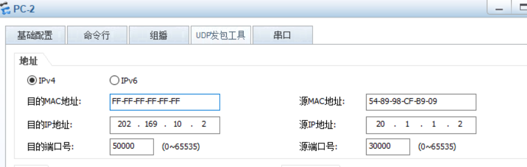
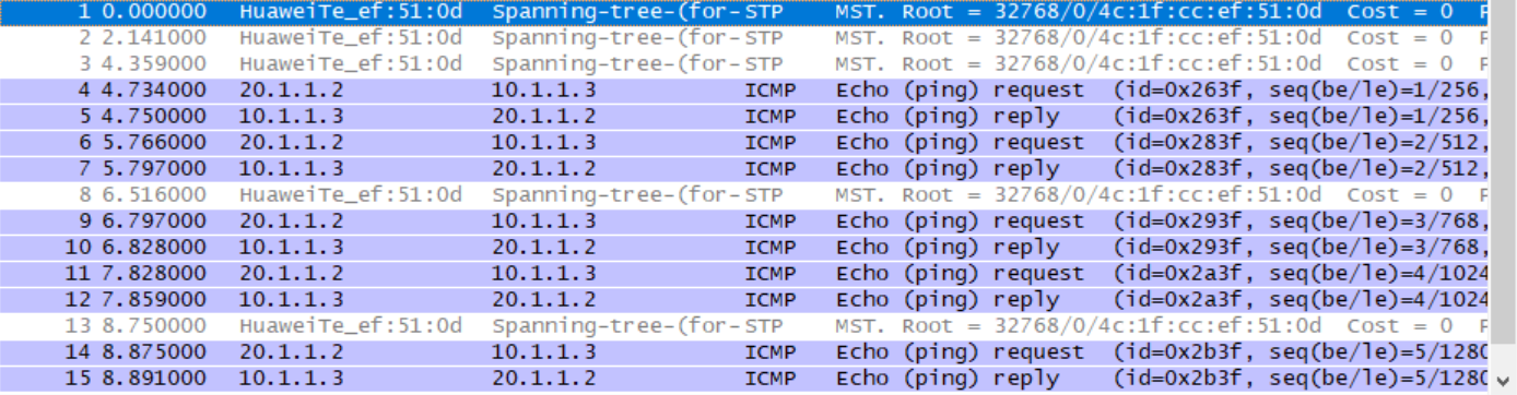
Overload means port multiplexing. As shown in the figure above, we sent a UDP packet to R2 with PC-2. At this time, the public IP used is the address of R1 0/0/0 interface. At the same time, the port number is mapped from 30000 to 40.
When we set the port numbers of PC2 and PC3 to 30000 and send udp packets to R2, the following situations will occur:
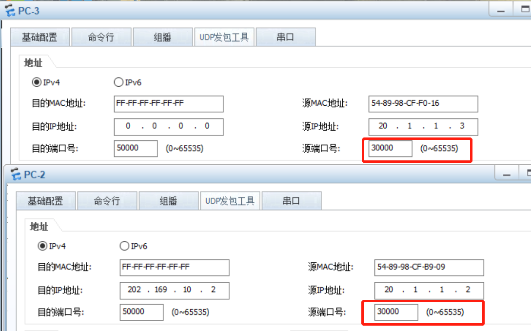

R2 cannot reach PC2 and PC3, and sends an ICMP destination unreachable message. In other words, NAPT not only realizes IP mapping, but also realizes port number mapping. At the same time, the computer in the intranet is identified by the port number. These ports are often one-time and unique.
Therefore, in a sense, NAPT destroys the clarity of stratification.