Subject requirements
Design tasks and requirements
- Digital tube display unit
The temperature information is displayed by 8-bit common positive nixie tube, including the set upper and lower temperature values and the current temperature values. The display format is shown in Figure 2: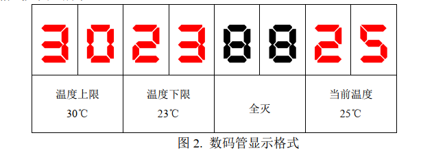
- Temperature measuring unit
The ambient temperature is measured by DS18B20 digital temperature chip. - Key control unit
The independent key S4 is set as the "increase upper limit" key; each time you press it, the temperature upper limit value increases by 1 ℃;
The independent key S5 is set as the "add lower limit" key; each time you press it, the temperature lower limit value increases by 1 ℃;
The independent key S6 is set as the "decrease upper limit" key, and the upper limit value of temperature is reduced by 1 ℃ every time it is pressed;
The independent key S7 is set as the "lower limit" key; each time the lower limit of temperature is pressed, the lower limit of temperature is reduced by 1 ℃. - EEPROM recording unit
The system stores the temperature information through AT24C02, and the internal storage addresses 0x00 and 0x01 of AT24C02 store the upper and lower limits of temperature data information respectively; the upper and lower limits of temperature data can be modified by external keys and displayed in real time through digital tubes. Data storage format is shown in Figure 3: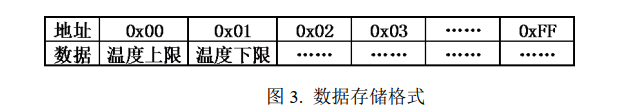
- Design of DC motor drive circuit
A DC motor driving circuit is designed to connect with P34 pin of single chip microcomputer. - Temperature control unit
If the current temperature value exceeds the upper temperature limit data stored in EEPROM, PWM signal with cycle of 1KHz and duty cycle of 30% is generated through P34 port of single chip microcomputer to drive DC motor. When the temperature returns to the upper and lower threshold values, P34 port outputs high level. If the current temperature is lower than the lower temperature limit data stored in EEPROM, the relay will turn on. When the temperature returns to the upper and lower threshold values, the relay will turn off automatically. - System initial state description
The upper and lower limit temperature values need to be set in the range of 0 ℃ to 99 ℃, and the lower limit value is not greater than the upper limit value. After the system is powered on, the upper and lower limit values of temperature are read from EEPROM, and the current temperature is displayed in real time.
Program code
Main function
#include<stc15f2k60s2.h>
#include "onewire.h"
#include "iic.h"

typedef unsigned char uchar;
typedef unsigned int uint;

sbit PWM=P3^4;
sbit dealy=P0^4;
sbit beep=P0^6;
uchar code SMG_duan[]={0x3F,0x06,0x5B,0x4F,0x66,0x6D,0x7D,0x07,0x7F,0x6F};
uchar code SMG_wei[]={0x01,0x02,0x04,0x08,0x10,0x20,0x40,0x80};

uchar temperature;
uchar max=30,min=23;   //Limit value
uchar limit_up=30,limit_down=23;
uchar temp_display[8];

uchar key_init();
void Timer0Init();		//1ms @ 11.0592MHz

void main()
{
   uchar key_val;
   P2=0XA0;P0=0X00;
   P2=0X80;P0=0XFF;

   Timer0Init();
   DS18B20();
   temp_display[4]=0x00;  temp_display[5]=0x00;
   while(1)
   {
      temperature=temp_get();

	  ET0=0;
	  max=Read(0x00);
	  min=Read(0x01);
	  limit_up=Read(0x00);
	  limit_down=Read(0x01);

	  ET0=1;
	  temp_display[0]=SMG_duan[max/10];	 temp_display[1]=SMG_duan[max%10];
	  temp_display[2]=SMG_duan[min/10];  temp_display[3]=SMG_duan[min%10];
	  temp_display[6]=SMG_duan[temperature%100/10];  temp_display[7]=SMG_duan[temperature%10];

	  key_val=key_init();
	  switch(key_val)
	  {
	     case 4:
		 		if(limit_up<99)
		        limit_up++;
				Write(0x00,limit_up);
				break;								//Upper limit
		 case 5:
				if(limit_down<99)
		        limit_down++;
				Write(0x01,limit_down);							//Lower limit
				break;
		 case 6:
		 		if(limit_up>0)
		 		limit_up--;
				Write(0x00,limit_up);
		 		break;
		 case 7:
		 		if(limit_down>0)
		 		limit_down--;
				Write(0x01,limit_down);
		 		break;
	  }
	  if(temperature>limit_up)
	  {
		PWM=1;
	  }
	  if(temperature<limit_down)
	  {
	     P2=0XA0;
		 dealy=1;
		 beep=0;
	  }
      if((limit_down<=temperature)&&(temperature<=limit_up))
	  {
	     P2=0XA0;
		 dealy=0;
		 beep=0;
		 PWM=0;
	  }

   }
}

#define KEY P3
#define key_state0 0
#define key_state1 1
#define key_state2 2

uchar key_init()
{
   static uchar key_state=0;
   uchar key_return=0,key_press;
   key_press=KEY&0X0F;

   switch(key_state)
   {
	 case key_state0:
	      if(key_press!=0x0f)
		  key_state=key_state1;
		  break;
	 case key_state1:
	      if(key_press!=0x0f)
		  {
			if(key_press==0x0e)   key_return=7;
			if(key_press==0x0d)   key_return=6;
			if(key_press==0x0b)   key_return=5;
			if(key_press==0x07)   key_return=4;
			key_state=key_state2;
		  }
		  else
		     key_state=key_state0;
		  break;
	 case key_state2:
	      if(key_press==0x0f)
		  key_state=key_state0;
		  break;
   }
   return key_return;
}

void Timer0Init()		//100us @11.0592MHz
{
	AUXR |= 0x80;		//Timer clock 1T mode
	TMOD &= 0xF0;		//Set timer mode
	TL0 = 0xAE;		//Set initial value of timing
	TH0 = 0xFB;		//Set initial value of timing
	TF0 = 0;		//Clear TF0 flag
	TR0 = 1;		//Timer 0 starts
	EA=1;
	ET0=1;
}

void Timer0() interrupt 1
{
   uchar i;
   static uint SMG_count=0,PWM_count=0;
   SMG_count++,PWM_count++;
   if(SMG_count==30)
   {
	  SMG_count=0;
	  P2=0XC0;P0=0X00;
	  P2=0XC0;P0=SMG_wei[i];
	  P2=0XE0;P0=~temp_display[i];
	  i++;
	  if(i==8)
	  i=0;
   }
   if(PWM_count==7)
   {
	  PWM=1;
   }
   if(PWM_count==10)
   {
	  PWM=0;
   }
}
DS18B20 temperature sensor
#include "onewire.h"
#include "intrins.h"
//Single bus delay function
void Delay_OneWire(unsigned int t)
{
  while(t--);
}
void Delay500us();
void Delay100us();
void Delay60us();
void Delay15us();

void delayms(unsigned char ms)
{
   int i,j;
   for(i=0;i<ms;i++)
     for(j=850;j>0;j--);
}
//DS18B20 chip initialization
bit Init_DS18B20(void)
{
	bit initflag = 0;
	DQ = 1;
	Delay_OneWire(12);
	DQ = 0;
	Delay500us();
	DQ = 1;
	Delay15us();
	initflag = DQ;
	Delay_OneWire(5);

	return initflag;
}

//Write a byte to DS18B20 through single bus
void Write_DS18B20(unsigned char dat)
{
	unsigned char i;
	for(i=0;i<8;i++)
	{
		DQ = 0;
		DQ = dat&0x01;
		Delay60us();
		DQ = 1;
		dat >>= 1;
	}
	Delay_OneWire(5);
}

//Read a byte from DS18B20
unsigned char Read_DS18B20(void)
{
	unsigned char i;
	unsigned char dat;

	for(i=0;i<8;i++)
	{
		DQ = 0;
		dat >>= 1;
		DQ = 1;
		if(DQ)
		{
			dat |= 0x80;
		}
		Delay100us();
	}
	return dat;
}

void DS18B20()
{
   Init_DS18B20();
   delayms(1);
   Write_DS18B20(0xcc);
   Write_DS18B20(0x44);

   Init_DS18B20();
   delayms(1);
   Write_DS18B20(0xcc);
   Write_DS18B20(0xbe);
}

int temp_get()
{
   unsigned char low,high;
   unsigned char temp;

   DS18B20();
   low=Read_DS18B20();
   high=Read_DS18B20();

   temp=high<<4;
   temp|=low>>4;

   return temp;
}
void Delay500us()		//@11.0592MHz
{
	unsigned char i, j;

	_nop_();
	_nop_();
	i = 6;
	j = 93;
	do
	{
		while (--j);
	} while (--i);
}

void Delay100us()		//@11.0592MHz
{
	unsigned char i, j;

	_nop_();
	_nop_();
	i = 2;
	j = 15;
	do
	{
		while (--j);
	} while (--i);
}

void Delay60us()		//@11.0592MHz
{
	unsigned char i, j;

	i = 1;
	j = 162;
	do
	{
		while (--j);
	} while (--i);
}

void Delay15us()		//@11.0592MHz
{
	unsigned char i;

	i = 39;
	while (--i);
}
EEPROM
/*
  Program description: IIC bus driver
  Software environment: Keil uVision 4.10
  Hardware environment: CT107 single chip integrated training platform (12MHz)
  Date: August 9, 2011
*/

#include "iic.h"

void iic_delay(unsigned char i)
{
    do
	{
	   _nop_();
	}while(i--);
}
void IIC_Start(void)
{
	SDA = 1;
	SCL = 1;
	iic_delay(5);
	SDA = 0;
	iic_delay(5);
	SCL = 0;
}

//Bus stop condition
void IIC_Stop(void)
{
	SDA = 0;
	SCL = 1;
	iic_delay(5);
	SDA = 1;
}
/*
//Response bit control
void IIC_Ack(unsigned char ackbit)
{
	if(ackbit)
	{
		SDA = 0;
	}
	else
	{
		SDA = 1;
	}
	iic_delay(5);
	SCL = 1;
	iic_delay(5);
	SCL = 0;
	SDA = 1;
	iic_delay(5);
}
*/
//Waiting response
bit IIC_WaitAck(void)
{
	SDA = 1;
	iic_delay(5);
	SCL = 1;
	iic_delay(5);
	if(SDA)
	{
		SCL = 0;
		IIC_Stop();
		return 0;
	}
	else
	{
		SCL = 0;
		return 1;
	}
}

//Send data through I2C bus
void IIC_SendByte(unsigned char byt)
{
	unsigned char i;
	for(i=0;i<8;i++)
	{
		if(byt&0x80)
		{
			SDA = 1;
		}
		else
		{
			SDA = 0;
		}
		iic_delay(5);
		SCL = 1;
		byt <<= 1;
		iic_delay(5);
		SCL = 0;
	}
}

//Receive data from I2C bus
unsigned char IIC_RecByte(void)
{
	unsigned char da;
	unsigned char i;

	for(i=0;i<8;i++)
	{
		SCL = 1;
		iic_delay(5);
		da <<= 1;
		if(SDA)
		da |= 0x01;
		SCL = 0;
		iic_delay(5);
	}
	return da;
}

void Write(unsigned char add,unsigned char dat)
{
   IIC_Start();
   IIC_SendByte(0xa0);
   IIC_WaitAck();
   IIC_SendByte(add);
   IIC_WaitAck();
   IIC_SendByte(dat);
   IIC_WaitAck();
   IIC_Stop();
}

unsigned char Read(unsigned char dat)
{
   unsigned char  temp;
   IIC_Start();
   IIC_SendByte(0xa0);						 //Write to 0
   IIC_WaitAck();
   IIC_SendByte(dat);
   IIC_WaitAck();

   IIC_Start();
   IIC_SendByte(0xa1);					   //Read out for 1
   IIC_WaitAck();
   temp=IIC_RecByte();
   IIC_Stop();

   return temp;
}
The above is the whole content of the code. You are welcome to criticize, correct and learn together~

