Note: This series blog was translated from Nathan Vaughn's Shaders Language Tutorial and has been authorized by the author. If reprinted or reposted, please be sure to mark the original link and description in the key position of the article after obtaining the author's consent as well as the translator's. If the article is helpful to you, click this Donation link to buy the author a cup of coffee.
Note: this series of blog posts is translated from Nathan Vaughn of Shader Language Tutorial . The article has been authorized by the author for translation. If you reprint it, please be sure to obtain it at author and translator After agreeing, indicate the original link and description in the key position of the article. If you think the article is helpful to you, click here Reward link Buy the author a cup of coffee.
Hello, friends! Today, we will learn how to use a pixel shader in Shadertoy Draw a circle on the and make it move.
practice
Before we draw the first 2D figure, let's use Shadertoy Let's do some exercises. newly build A shader and copy the following code into it:
  void mainImage( out vec4 fragColor, in vec2 fragCoord )
{
  vec2 uv = fragCoord/iResolution.xy; // <0,1>

  vec3 col = vec3(0); // start with black

  if (uv.x > .5) col = vec3(1); // make the right half of the canvas white

  // Output to screen
  fragColor = vec4(col,1.0);
}
Because our shader runs on each pixel at the same time, we need to use the if conditional branch to draw different colors according to the position of each pixel. Your shader code depends on the graphics card and compiler, using built-in functions such as step Would be more appropriate.
Let's take a look at the example of using the step function as a replacement:
  void mainImage( out vec4 fragColor, in vec2 fragCoord )
{
  vec2 uv = fragCoord/iResolution.xy; // <0,1>

  vec3 col = vec3(0); // start with black

  col = vec3(step(0.5, uv.x)); // make the right half of the canvas white

  // Output to screen
  fragColor = vec4(col,1.0);
}
The left side of the canvas turns black and the right side turns white.

step The function takes two arguments: a boundary value and a contrast value. If the second parameter in the function is greater than the first, it returns 1, otherwise it returns 0. You can also apply the return value of step as several element values in a vector:
void mainImage( out vec4 fragColor, in vec2 fragCoord )
{
  vec2 uv = fragCoord/iResolution.xy; // <0,1>

  vec3 col = vec3(0); // start with black

  col = vec3(step(0.5, uv), 0); // perform step function across the x-component and y-component of uv

  // Output to screen
  fragColor = vec4(col,1.0);
}
Because the step function handles both X and Y elements on the canvas, you can see that the canvas is divided into four color blocks:

Draw circle
Here's how to define a circle Basic formula:
x^2 + y^2 = r^2

  x = x- Coordinate values on the image
  y = y- Coordinate values on the image
  r = Radius of circle
We readjust the position of the variable so that the equation is 0:
x^2 + y^2 - r^2 = 0
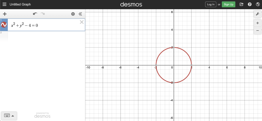
If you want to show this formula graphically, you can use Desmos calculator Help you visualize the formula:
x^2 + y^2 - 4 = 0
Paste the above code and copy it to Desmos calculator. You can see a circle with radius of 2. The position of the center point of the circle is the coordinate origin (0, 0);

In Shadertoy, we use the above formula to draw a circle. First, create an sdfCircle function. This function will return white when the XY coordinate is greater than 0, otherwise it will return blue.
The sdf function refers to the symbolic distance field function( signed distance functions[SDF] )The concept of. SDF is often used to draw 3D graphics, but we can also use it to draw 2D graphics here. We call them in the new mainImage function:
vec3 sdfCircle(vec2 uv, float r) {
    float x = uv.x;
    float y = uv.y;

    float d = length(vec2(x, y)) - r;

    return d > 0. ? vec3(1.) : vec3(0., 0., 1.);
}

void mainImage( out vec4 fragColor, in vec2 fragCoord )
{
  vec2 uv = fragCoord/iResolution.xy; // <0,1>

  vec3 col = sdfCircle(uv, .2); // Call this function on each pixel to check if the coordinate lies inside or outside of the circle

  // Output to screen
  fragColor = vec4(col,1.0);
}
You may wonder, why should I add a decimal point after the number 0? This is because adding a decimal point can convert integer numbers to floating-point numbers. When we call a function that needs to pass in floating-point parameters, adding a "point" after the integer can ensure that the compiler will compile our code correctly.
We set the radius to 0.2 because the UV value of the coordinate system is between 0 and 1. Run the code, and you will notice that there seems to be a problem with our graphics:

It looks like just a quarter circle in the lower left corner of the canvas. The reason for this phenomenon is that the initial origin coordinate of our canvas is in the lower left corner. We need to offset the XY coordinate by 0.5 so that it can be located in the center of the canvas:
UV coordinate value minus 0.5
  vec2 uv = fragCoord/iResolution.xy; // <0,1>
  uv -= 0.5; // <-0.5, 0.5>
Now, the coordinate range of X axis and Y axis on the canvas is - 0.5 and 0.5, which means that the origin of the coordinate is in the center of the canvas. However, we have encountered a new problem:

Our circle is a little stretched and looks more like an ellipse. The reason for this phenomenon is the width height ratio of the canvas. When the width and height of the canvas are different, our circle will be stretched. The solution is to multiply the X coordinate in the UV by the canvas aspect ratio:
  vec2 uv = fragCoord/iResolution.xy; // <0,1>
  uv -= 0.5; // <-0.5, 0.5>
  uv.x *= iResolution.x/iResolution.y; // fix aspect ratio
This means that the range of the X-axis is no longer between - 0.5 and 0.5, but a proportional value that automatically adapts to the width height ratio of the canvas according to the width of your browser and interface (the width of the interface may be narrowed because the debugging mode is turned on). The final code should look like this:
  vec3 sdfCircle(vec2 uv, float r) {
    float x = uv.x;
    float y = uv.y;

    float d = length(vec2(x, y)) - r;

    return d > 0. ? vec3(1.) : vec3(0., 0., 1.);
 }

void mainImage( out vec4 fragColor, in vec2 fragCoord )
{
  vec2 uv = fragCoord/iResolution.xy; // <0,1>
  uv -= 0.5;
  uv.x *= iResolution.x/iResolution.y; // fix aspect ratio

  vec3 col = sdfCircle(uv, .2);

  // Output to screen
  fragColor = vec4(col,1.0);
}
Run the above code, you can see a perfect proportion of the blue circle! 🎉
Tip: This is just one way to draw a circle. In the fourth tutorial, we will learn another method, which can not only help us draw circles, but also draw other graphics.
Now let's have some fun! We can use the global variable iTime to transform the color of the circle. Using the cosine (cos) function, we can change a set of colors repeatedly. Because the amplitude of cosine function is between - 1 and 1, we need to adjust it to between 0 and 1.
Don't forget that the last output color value of the slice shader will be between 0 and 1. If the color value is less than 0, it will be automatically converted to 0. If it is greater than 1, it will be automatically converted to 1 for us. By adjusting the range, we can get a wide range of color values.
  vec3 sdfCircle(vec2 uv, float r) {
  float x = uv.x;
  float y = uv.y;

  float d = length(vec2(x, y)) - r;

  return d > 0. ? vec3(0.) : 0.5 + 0.5 * cos(iTime + uv.xyx + vec3(0,2,4));
}

void mainImage( out vec4 fragColor, in vec2 fragCoord )
{
  vec2 uv = fragCoord/iResolution.xy; // <0,1>
  uv -= 0.5;
  uv.x *= iResolution.x/iResolution.y; // fix aspect ratio

  vec3 col = sdfCircle(uv, .2);

  // Output to screen
  fragColor = vec4(col,1.0);
}
Running the above code, you can see a circle that changes between multiple colors.

Are you confused about the grammar of uv.xyx? This grammar is called Swizzling . We can declare a vector containing multiple elements. As follows:
  vec3 col = vec3(0.2, 0.4, 0.6);
  vec3 col2 = col.xyx;
  vec3 col3 = vec3(0.2, 0.4, 0.2);
In the above code snippet, col2 and col3 have the same effect.
Let the circle move
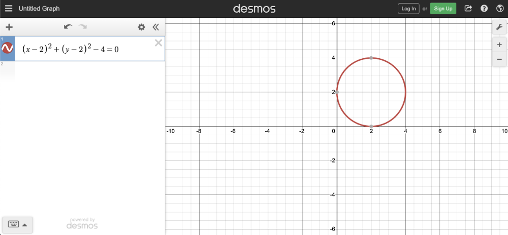
To make the circle move, we need to set an offset value for the X and Y coordinates in the circle formula. Therefore, the equation is modified as follows:
  (x - offsetX)^2 + (y - offsetY)^2 - r^2 = 0
  x = x-coordinate on graph
  y = y-coordinate on graph
  r = radius of circle
  offsetX = how much to move the center of the circle in the x-axis
  offsetY = how much to move the center of the circle in the y-axis
We copy the code to Desmos calculator Go to, and you can see the graphical results:

In Shadertoy, we adapt the offset value by adjusting the sdfCircle function, and then move the circle by 0.2 to the upper right corner:
  vec3 sdfCircle(vec2 uv, float r, vec2 offset) {
  float x = uv.x - offset.x;
  float y = uv.y - offset.y;

  float d = length(vec2(x, y)) - r;

  return d > 0. ? vec3(1.) : vec3(0., 0., 1.);
}

void mainImage( out vec4 fragColor, in vec2 fragCoord )
{
  vec2 uv = fragCoord/iResolution.xy; // <0,1>
  uv -= 0.5;
  uv.x *= iResolution.x/iResolution.y; // fix aspect ratio

  vec2 offset = vec2(0.2, 0.2); // move the circle 0.2 units to the right and 0.2 units up

  vec3 col = sdfCircle(uv, .2, offset);

  // Output to screen
  fragColor = vec4(col,1.0);
}

Use the global variable iTime to bring the canvas to life and make the circle move.
  vec3 sdfCircle(vec2 uv, float r, vec2 offset) {
  float x = uv.x - offset.x;
  float y = uv.y - offset.y;

  float d = length(vec2(x, y)) - r;

  return d > 0. ? vec3(1.) : vec3(0., 0., 1.);
}

void mainImage( out vec4 fragColor, in vec2 fragCoord )
{
  vec2 uv = fragCoord/iResolution.xy; // <0,1>
  uv -= 0.5;
  uv.x *= iResolution.x/iResolution.y; // fix aspect ratio

  vec2 offset = vec2(sin(iTime*2.)*0.2, cos(iTime*2.)*0.2); // move the circle clockwise

  vec3 col = sdfCircle(uv, .2, offset);

  // Output to screen
  fragColor = vec4(col,1.0);
}
The above code will make the circle rotate clockwise around the canvas origin along a circular track. Multiply iTime by a value to adjust the rate of animation. The amplitude of the motion can be adjusted by multiplying the returned values of sine and cosine by a value. Later, we will often use sine and cosine functions with iTime variables. Because they resonate!

summary
In this tutorial, we learned that if we modify the coordinate system of the canvas, draw a circle, and then let it move along the circular track. Round! Round! Round! 🔵. In the next lesson, I will show you how to draw a box and rotate it!