Windmill
Custom View of a Rotary Windmill Imitating Huawei Weather
I'm working on a weather forecast app recently. Because I use Huawei's mobile phone. It is found that Huawei's weather forecast software is quite good. So the main interface of my weather forecast software mainly imitates Huawei's weather. App address OneWeather.
This rotating windmill is one of the custom View s. The self-perception is good. Novice one, what can be perfected or misunderstood wrong place welcome to put forward oh.
GitHub source address: Windmill source code
(star if you like!)
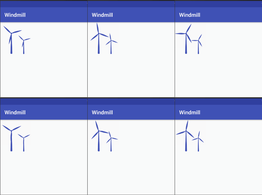
The results are as follows:

1. overview
Windmill blade and windmill pole are in the same View. Animation mainly uses attribute animation to control the angle, and then redraws the position of the blade. The calculation of this position needs the knowledge of trigonometric function. Unfortunately, I basically forgot those formulas, which led me to work out the correct formula in this piece for a long time.
2. Variables and initialization
The radian is the radian of the blade from its original position.
Take the windmill midpoint as the center and origin, i.e. (x1,y1).
The center of the circle is connected to four other points, so there will be four radians and four bevels. (x1,y1) and (x2,y2) are r1 and rad1, and so on.
private Paint mWindmillPaint; //Pillar brush

    private Path mWindPath;

    private Path mPillarPath;

    private int width,height;

    private int mWindmillColor;//Windmill color

    private float mWindLengthPercent;//Fan blade length

    private Point mCenterPoint;//Center of a circle

    private float x1,y1,x2,y2,x3,y3,x4,y4,x5,y5;//Fan blade point

    private double rad1,rad2,rad3,rad4;//radian

    private double r1,r2,r3,r4;//Hypotenuse

    private ObjectAnimator mAnimator;//animation

    private float angle;//Rotation angle

    private int windSpeed = 1;
 private void init(AttributeSet attrs) {

        initAttrs(attrs);


        mWindmillPaint = new Paint();

        mCenterPoint = new Point();

        mWindmillPaint.setStyle(Paint.Style.FILL);

        mWindmillPaint.setStrokeWidth(2);//Set Brush Thickness

        mWindmillPaint.setAntiAlias(true);

        mWindmillPaint.setColor(mWindmillColor);


        mAnimator = ObjectAnimator.ofFloat(this,"angle",0,(float)(2*PI));//

        mAnimator.setRepeatCount(ValueAnimator.INFINITE);

        mAnimator.setInterpolator(new LinearInterpolator());


    }
3. Drawing Windmills
The Bessel curve is used to draw both the column and the blade. In fact, the straight line can also be used. If you haven't heard of the Bessel curve, you can search for it. A tutorial in a brief book In fact, I haven't looked at it carefully. It seems that many beautiful custom views will be used, or remember that the Bessel curve is to turn sharp corners into an arc.
mWindPath.cubicTo(x2,y2,x3,y3,x4,y4);
mWindPath.quadTo(x5,y5,x1,y1);
These two functions are used to draw Bessel curves.
(x1,y1)... (x5,y5) These five points are the points on the blade
The blade is drawn by drawing one piece and then rotating the canvas 120 degrees to draw the other two pieces. A better solution is not to move to locate the path.
Pillars and leaves
private void drawPillar(Canvas canvas) {

        mPillarPath = new Path();

        mPillarPath.moveTo(mCenterPoint.x-width/90,mCenterPoint.y-width/90);

        mPillarPath.lineTo(mCenterPoint.x+width/90,mCenterPoint.y-width/90);//Connection

        mPillarPath.lineTo(mCenterPoint.x+width/35,height-height/35);

        mPillarPath.quadTo(mCenterPoint.x,height,mCenterPoint.x-width/35,height-height/35);//Bessel Curve, Control Point and Endpoint

        mPillarPath.close();//Closed graph

        canvas.drawPath(mPillarPath,mWindmillPaint);


    }

    private void drawWind(Canvas canvas) {

        mWindPath = new Path();

        canvas.drawCircle(mCenterPoint.x,mCenterPoint.y,width/40,mWindmillPaint);

        mWindPath.moveTo(x1,y1);

        x2 = mCenterPoint.x + (float) (r1 * Math.cos(rad1 + angle));

        y2 = mCenterPoint.y + (float) (r1 * Math.sin(rad1 + angle));

        x3 = mCenterPoint.x + (float) (r2 * Math.cos(rad2 + angle));

        y3 = mCenterPoint.y + (float) (r2 * Math.sin(rad2 + angle));

        x4 = mCenterPoint.x + (float) (r3 * Math.cos(rad3 + angle));

        y4 = mCenterPoint.y + (float) (r3 * Math.sin(rad3 + angle));

        x5 = mCenterPoint.x + (float) (r4 * Math.cos(rad4 + angle));

        y5 = mCenterPoint.y + (float) (r4 * Math.sin(rad4 + angle));


        mWindPath.cubicTo(x2,y2,x3,y3,x4,y4);

        mWindPath.quadTo(x5,y5,x1,y1);

        canvas.drawPath(mWindPath,mWindmillPaint);

        canvas.rotate(120,mCenterPoint.x,mCenterPoint.y);

        canvas.drawPath(mWindPath,mWindmillPaint);

        canvas.rotate(120,mCenterPoint.x,mCenterPoint.y);

        canvas.drawPath(mWindPath,mWindmillPaint);

        canvas.rotate(120,mCenterPoint.x,mCenterPoint.y);

    }
4. animation
Using the property animation Object Animator,
Set the number of repetitions, the range of radian change from 0 to 2 PI is 360 degrees, linear change.
mAnimator = ObjectAnimator.ofFloat(this,"angle",0,(float)(2*PI));//

        mAnimator.setRepeatCount(ValueAnimator.INFINITE);

        mAnimator.setInterpolator(new LinearInterpolator());
WindsSpeed controls the speed of windmill, which is actually to shorten the animation cycle.
 public void startAnimation(){

        mAnimator.setDuration((long) (10000/(windSpeed*0.80)));//Multiply the coefficient less than 1 to reduce the impact

        mAnimator.start();

    }
Calculations of Radius and Inclined Edge of Initial Point
Here I calculate that the initial blade is located on the positive and half axes of the y axis.
The rad is the radian of the angle between the positive and half axes of the x-axis.
Here width/15, width/30 are used to control the thickness of the blade, which can be changed, but to keep the radian and beveled edges consistent with the corresponding values. In fact, we should make a variable.
   private void setBladeLocate() {


        x1 = mCenterPoint.x;

        y1 = mCenterPoint.y;


        //Radian (radian)

        rad1 = atan(width/15/(width/30)); //The angle formed by x1,y1 and x2,y2 takes the circular point as the origin of coordinates, and returns the angle from - pi/2 to pi/2 artan (y/x).

        rad2 = atan(width/6/(width/30));//x1,y1 and x3,y3

        rad3 = PI/2;//tan90 does not exist

        rad4 = atan(mCenterPoint.y/2/(-width/30))+PI;//Because the return angle is - pi/2 to pi, add PI


        //r is the length of the diagonal edge, which corresponds to the length of the diagonal edge above.

        r1 = Math.hypot(width/30,width/15);

        r2 = Math.hypot(width/30,width/6);

        r3 = Math.hypot(0,mCenterPoint.y);

        r4 = Math.hypot(width/30,mCenterPoint.y/2);

    }
The Relation between angle Change Process and Coordinate Points
rad+angle is the angle relative to the x-axis.
r1 is a bevel edge.
The beveled edge multiplied by cos is the adjacent edge.
cos = adjacent / oblique
x2 = mCenterPoint.x + (float) (r1 * Math.cos(rad1 + angle));

y2 = mCenterPoint.y + (float) (r1 * Math.sin(rad1 + angle));

x3 = mCenterPoint.x + (float) (r2 * Math.cos(rad2 + angle));

y3 = mCenterPoint.y + (float) (r2 * Math.sin(rad2 + angle));
In fact, the conversion of the above two parts into mathematical problems is:
Know the radius and angle, and find the end coordinates of the line starting from the origin.
5. Property Settings and Layout
The xml attribute defined here is only the ratio of windmill color and windmill blade to total length, which is better after testing about 0.35.
Windmill speed is generally transmitted from the outside, through the code settings.
<attr name="windmillColors"format="color|reference"/>

<attr name="windLengthPerent" format="float" />
layout
Size, color and leaf proportion can be set at will.
<?xml version="1.0" encoding="utf-8"?>

<RelativeLayout xmlns:android="http://schemas.android.com/apk/res/android"

    xmlns:app="http://schemas.android.com/apk/res-auto"

    android:layout_width="140dp"

    android:layout_height="match_parent">


    <com.yogw.windmill.Windmill

        android:id="@+id/windmill_big"

        android:layout_width="120dp"

        android:layout_height="120dp"

        app:windLengthPerent="0.35"

        app:windmillColors="@color/colorPrimary"

        android:layout_alignParentLeft="true"/>

    <com.yogw.windmill.Windmill

        android:id="@+id/windmill_small"

        android:layout_width="80dp"

        android:layout_height="80dp"

        app:windLengthPerent="0.35"

        app:windmillColors="@color/colorPrimary"

        android:layout_alignParentRight="true"

        android:layout_alignBottom="@+id/windmill_big"/>


</RelativeLayout>
Source address: https://github.com/YugengWang/Windmill
If you can help me, please click star. Thank you.