At the end of last semester, the lower computer is used to control the underlying hardware. However, the price of STM32 boards has gone up dramatically. Seeing that more than a dozen boards have gone up to nearly 40 at a time, the raspberry pie pico boards with similar functions have been shown to me. Although in the end, I used STM32 boards for stability, I also managed to get some Picos to play with.
The online tutorials on pico are small and fragmented, and I can only read Official Documents Learn slowly. At present, the notes are not complete or even a little confused, but they may help later people get started as soon as possible.
Up brusher
Very simple, press and hold the BOOTSET key to connect the computer with microUSB, then you can use uf2 program to brush the machine in the way of file copy.
The uf2 file for MicroPython can be downloaded from here: microPython environment
For C/C++, uf2 files need to be compiled and then burned into the board.

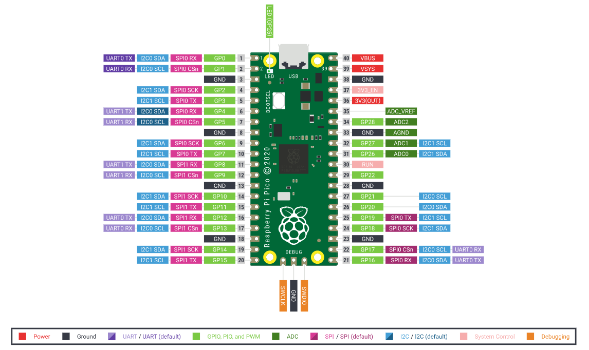
Pipe Chart
MicroPython Control
machine module
machine.Pin
GPIO class. The operation of GPIO can be accomplished by code like the following.
switch = Pin(0, Pin.IN, Pin.PULL_DOWN)  # Set drop-down input
trigger = Pin(1, Pin.IN, Pin.PULL_UP)  # Set up pull-up input
led = Pin(25, Pin.OUT)  # On-board LED is GP 25

state = 0
def change():
    global state
    state = 1-state

def setLED(pin):  # Interrupt handler to receive a Pin object whose argument is the trigger
    led.value(state)
    # value() returns the pin value when no parameter is present
    # With parameters, value(i) sets the pin value to I

trigger.irq(setLED, Pin.IRQ_FALLING)  # Set drop edge to trigger interrupt

while True:
    if switch.value():  # If high level
        change()
        while switch.value():
            pass  # Wait until you fall back to low level
Pin setting is quite convenient~
Initialization:
Initialization requires at least a GP pin. The physical pin corresponding to the GP is shown in the figure above. An I/O is also specified. If not, the pin is set at 0 by default.
p1 = Pin(0)
p2 = Pin(1, Pin.IN)
p3 = Pin(2, Pin.OUT)
When specified as OUT, pins are initially low level. Pins can be positioned with high() or on() functions, reset with low() or off() functions, directly specified with value(v) functions, and inverted with toggle() functions. At this time, pin levels can also be queried with value() functions. Specifically, the following two sections can be seen.
When specified as IN, the pin initial level is the level at which it was initialized, but the pull-up and pull-down inputs can be specified:
p4 = Pin(3, Pin.IN, Pin.PULL_UP)
p5 = Pin(4, Pin.IN, Pin.PULL_DOWN)
At this time, high(), low(), on(), off(), toggle() and value(v) can be called successfully but will not take effect. Use the value() function to query pin level normally.
In addition to the default initialization, you can use the reinitialization function init(), which is the same as above, except that pins are not required.
Set pin level:
Only set for OUT GP. High level is 3V3.
Use high(), on(), value(1) to position, i.e. the pin level is high; use low(), off(), value(0) to reset, i.e., the pin level is low; use toggle() to reverse the height.
led = Pin(25, Pin.OUT)
led.high()
sleep(2)
led.low()
sleep(3)
while True:
    led.toggle()
    sleep(0.5)
Read pin level:
Readable for all kinds of GP s.
Use value() to read, high returns 1, low returns 0.
led = Pin(25, Pin.OUT)
button = Pin(0, Pin.IN, Pin.PULL_DOWN)
while True:
    led.value(button.value())
Setup/Query Interrupt:
Interrupts can be set for all types of GP s.
Set using the irq(func[, flag]) function. The first parameter specifies the function that triggers the interrupt call. The function must have one parameter to receive the Pin object that triggers the interrupt. The second parameter is optional to specify the rise/fall edge trigger. The default is IRQ_FALLING | IRQ_RISING, which is triggered by any change in the level.
The function returns the irq object of the GP. Its flags() method queries the current trigger state, or 0 if it is not triggered, or it is one of IRQ_FALLING or IRQ_RISING. Its trigger() method returns the type of interrupt, or 0 if no interrupt is set, or one of IRQ_FALLING, IRQ_RISING, or IRQ_FALLING | IRQ_RISING.
A parameter-free call to irq() returns only the IRQ object of the GP.
button = Pin(0, Pin.IN, Pin.PULL_UP)

def handler(pin):
    print('I am pulled down.' if pin.irq().flags() == Pin.IRQ_FALLING else 'I am pulled up.')

button.irq(handler)
machine.PWM
Go straight to the official routine, because it's easy.
Official routines:
# Example using PWM to fade an LED.
import time
from machine import Pin, PWM

# Construct PWM object, with LED on Pin(25).
pwm = PWM(Pin(25))

# Set the PWM frequency.
pwm.freq(1000)

# Fade the LED in and out a few times.
duty = 0
direction = 1
for _ in range(8 * 256):
	duty += direction
	if duty > 255:
		duty = 255
		direction = -1
	elif duty < 0:
		duty = 0
		direction = 1
	pwm.duty_u16(duty * duty)
	time.sleep(0.001)
Initialization:
Initialize with a Pin object:
led = Pin(25, Pin.OUT)
pwm = PWM(led)
wave = PWM(Pin(0))
Set/Query Frequency:
freq(f) is used to set the frequency. Frequency is at least 10 Hz (8 Hz is also possible), up to 125 MHz. Settings outside the range can cause errors, and some high accuracy settings are automatically rounded to nearby crossover allowable values.
freq() without parameters is used to query the frequency, and the return value is frequency.
Set/Query Duty Cycle:
There are two modes: counting mode and timing mode.
duty_u16(d) is set for count mode, duty ratio
d
65535
×
100
%
{d\over 65535}\times100 \%
65535d×100%
Due to internal settings, some settings will be changed to nearby, more hardware-friendly values. If the limit of 65535 is exceeded, strange results will be obtained.
A parameterless call to duty_u16() yields the above d-value.
duty_ns(t) is set for the timing mode to set the duration (in nanoseconds) of the high level for each cycle. If the frequency is set to f, the duty cycle is
t
f
×
1
0
−
9
×
100
%
tf\times10^{-9} \times100\%
tf×10−9×100%
Also because of the internal settings, the actual value will be a little different from the specified value.
A parameterless call to duty_ns() yields the above t-value.
The initial frequency was 1907Hz (I tried it several times, as if it were), and the duty cycle was 0.
Stop it:
Use the deinit() function to pause the generation of PWM waves, and set the duty cycle to resume. The pause will maintain the level of the pause instant. Setting the frequency will not resume the PWM waves.
machine.UART
Official routines:
from machine import UART, Pin
import time

uart1 = UART(1, baudrate=9600, tx=Pin(8), rx=Pin(9))

uart0 = UART(0, baudrate=9600, tx=Pin(0), rx=Pin(1))

txData = b'hello world\n\r'
uart1.write(txData)
time.sleep(0.1)
rxData = bytes()
while uart0.any() > 0:
    rxData += uart0.read(1)

print(rxData.decode('utf-8'))
(True, clear at a glance. Wait until you've finished)
machine.SPI
Initialization:
spi = SPI(0
          baudrate=1000000,  # baud rate
          polarity=0,        # Clock default level
          phase=0,           # Up/Down Edge Read
          bits=8,            # position
          firstbit=SPI.MSB,  # Reverse/Order
          sck=Pin(2),        # Specify clock port
          mosi=Pin(3),       # Specify Output Port
          miso=Pin(4)        # Specify Input Port
)
(Usage similar to UART)
C/C++ Control
All operations here are performed on Linux systems. Windows can also install related SDK s, but has not yet tried them.
I see this section Official Documents Notes taken in the diary should be based on documentation when developing.
I personally feel that, after getting started, it is not as efficient to read the notes of predecessors as to read the documents directly.
SDK Configuration
If you want to be lazy, get the script directly from the official channel and run it.
wget https://raw.githubusercontent.com/raspberrypi/pico-setup/master/pico_setup.sh
sudo bash ./pico_setup.sh
You can read the script code to confirm its operation before running.
You can also install it yourself step by step:
-
Choose a geomancy site. Try not to include any other folders.
-
Install dependent packages:
sudo apt update
sudo apt install cmake gcc-arm-none-eabi libnewlib-arm-none-eabi build-essential
-
Clone the SDK, or you can choose to clone the sample program:
git clone -b master https://github.com/raspberrypi/pico-sdk.git
cd pico-sdk
git submodule update --init
cd ..
git clone -b master https://github.com/raspberrypi/pico-examples.git
Be careful to create the folder you want.
-
Create folders under their own folders and compile them.
cmake ../
make -j4
-
Also, remember to check for updates from time to time:
cd pico-sdk
git pull
git submodule update
program
stdio
This header file needs to be included:
#include <stdio.h>
Input and output streams can be specified as USB or normal serial ports, which are used by default. Set in CMakeLists.txt
pico_enable_stdio_usb(mylowvel 1)
pico_enable_stdio_uart(mylowvel 0)
To enable USB IO. When using USB, you can use functions within tusb.h to help determine if the USB connection is successful, thus avoiding problems that the upper computer cannot detect:
#include <tusb.h>
// ...
while(!tud_cdc_connected());
Before using library functions in your program, you need to initialize them:
stdio_init_all();
Other available functions are those in the standard C language, such as printf, getchar, and so on.
GPIO
You need to include these two headers:
#include "pico/stdlib.h"
#include "hardware/gpio.h"
Initialize a GPIO:
gpio_init(GP_id);
Set/query the input/output direction of a GPIO:
gpio_set_dir(GP_id, GPIO_OUT);  // Or GPIO_IN
gpio_get_dir(GP_id);
Set/query a GPIO for pull-up/drop-down input:
gpio_pull_up(GP_id);
gpio_is_pulled_up(GP_id);  // Return true/false
gpio_pull_down(GP_id);
gpio_is_pulled_down(GP_id);  // Return true/false

gpio_set_pulls(GP_id, true, false);  // The second parameter specifies a drop-down, and the third parameter specifies a drop-down
Set/query the level of a GPIO:
gpio_put(GP_id, true);  // Or false
gpio_get(GP_id);  // Return true/false
IRQ interrupt
You need to include these three headers:
#include "pico/stdlib.h"
#include "hardware/gpio.h"
#include "hardware/irq.h"
Set interrupt handling:
gpio_set_irq_enabled_with_callback(GP_id,
                                   GPIO_IRQ_EDGE_FALL,  // Or other interrupt events, such as GPIO_IRQ_EDGE_RISE, etc.
                                   true,                // true is enabled immediately
                                   &handlingFunction);
Interrupt handler type:
void handlingFunction(uint gpio, uint32_t events);
PWM
These headers need to be included:
#include "pico/stdlib.h"
#include "hardware/gpio.h"
#include "hardware/pwm.h"
#include "hardware/clocks.h" //If the system clock frequency is not used, ignore
Set the specified GPIO to PWM output:
gpio_set_function(GP_id, GPIO_FUNC_PWM);
Set GPIO frequency:
uint wrap;
uint slice_num = pwm_gpio_to_slice_num(GP_id);
pwm_set_wrap(slice_num, wrap);  // Set frequency to (125M/wrap)Hz
Be careful:
The above method sets wrap up to 65535. If you want to set a smaller frequency, you need to set the PWM crossover manually:
uint freq;  // Frequency to set
uint wrap;  // Top value
uint times; // division factor
uint slice_num = pwm_gpio_to_slice_num(GP_id);
pwm_set_enabled(slice_num, true);  // Enable. It looks like there's no such thing.
pwm_config config = pwm_get_default_config();  // Use a setup structure to prepare for subsequent initialization
float div = (float)clock_get_hz(clk_sys) / (freq * times);
pwm_config_set_clkdiv(&config, div);
pwm_config_set_wrap(&config, wrap);
pwm_init(slice_num, &config, true);
It is important to note that wrap is relative to the clock after crossover. The expression in the program can be in other situations, but should ultimately be:
t
i
m
e
s
×
w
r
a
p
=
c
l
k
_
s
y
s
=
125
M
H
z
times\times wrap=clk\_sys=125\ {\rm MHz}
times×wrap=clk_sys=125 MHz
Set duty cycle:
pwm_set_gpio_level(GP_id, level); // Set duty cycle (level/wrap) *100%
UART
These headers need to be included:
#include "pico/stdlib.h"
#include "hardware/gpio.h"
#include "hardware/uart.h"
Initialization:
uart_init(UART_id, 115200);  // UART_id is uart0 or uart1, identifiers are defined
gpio_set_function(GP_id, GPIO_FUNC_UART);  // Register the matching TX as UART port, referring to the above figure
gpio_set_function(GP_id, GPIO_FUNC_UART);  // Register the matching RX as a UART port, referring to the above figure
uart_set_baudrate(UART_id, 115200);  // Set baud rate, default 115200
uart_set_format(UART_id, 8, 1, 0);  // Set data bits, stop bits, check bits, default 8/1/0
Query if the serial port is readable/writable:
uart_is_readable(UART_id);  // Return true/false
uart_is_writable(UART_id);  // Return true/false
Read/write serial port:
uart_getc(UART_id);  // Return read characters
uart_putc(UART_id, 'c');
uart_puts(UART_id, "string");
Compile
After completing the above SDK configuration and programming, you only need to be aware of the configuration of CMakeLists.txt.
cmake_minimum_required(VERSION 3.12)

include(pico_sdk_import.cmake)

project(your_project_name C CXX ASM)
set(CMAKE_C_STANDARD 11)
set(CMAKE_CXX_STANDARD 17)

pico_sdk_init()

add_executable(your_project_name
        c_or_cpp_file.c
        )

target_link_libraries(your_project_name pico_stdlib)

pico_add_extra_outputs(your_project_name)

add_compile_options(-Wall
        -Wno-format
        -Wno-unused-function
        -Wno-maybe-uninitialized
        )
Where the pico_sdk_import.cmake file can be copied directly from <PICO_SDK_PATH>/external/pico_sdk_import.cmake.
Then there's the stereotype:
mkdir build
cd build
cmake ..
make -j4
Be careful:
When compiling, try to include only half-corner English in the full path name of the directory you are in. make has a high probability of making errors when the path name is known to exist in Chinese!