Directory outline
- Theoretical framework
- Basic outline
- 1. Affine transformation and perspective transformation
- 2. The definition of image coordinate system, camera coordinate system and world coordinate system, and the transformation relationship among them.
- 3. Internal and external parameter matrix of camera
- 4. Solving relative pose by linear method
- 5. Zhang's calibration method
- Code practice
Theoretical framework
Basic knowledge summary:
https://blog.csdn.net/weixin_42237113/article/details/104500993
API detailed explanation:
https://blog.csdn.net/weixin_42237113/article/details/104488809
Basic outline
1. Affine transformation and perspective transformation
affine transformation
Also known as affine mapping, it means that in geometry, a vector space is transformed into another vector space by a linear transformation and a translation. Affine transformation is defined geometrically as an affine transformation or affine mapping between two vector spaces Correlation) consists of a nonsingular linear transformation (transformation by using a primary function) followed by a translation transformation. The basic expression is as follows:
For example: after a picture is rotated 30 degrees anticlockwise, the change of related pictures can be called affine transformation. In fact, translation, scaling and rotation can be a special case of affine change.
Perspective change
Perspective transformation refers to the transformation that uses the condition that the perspective center, image point and target point are collinear, according to the perspective rotation law, the bearing surface (perspective surface) rotates around the trace (perspective axis) by an angle, destroys the original projection beam, and still keeps the projection geometry on the bearing surface unchanged. In short, it is the process of transforming the three-dimensional image of an object into two-dimensional features, which is called perspective change. It is represented by the formula as follows:
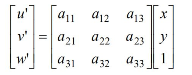
For example: the aerial view of the railway track is parallel, but standing on the ground to see the railway track intersects at a point in the distance.
2. The definition of image coordinate system, camera coordinate system and world coordinate system, and the transformation relationship among them.
Image coordinate system, camera coordinate system and world coordinate system
Image processing, stereo vision and other directions often involve four coordinate systems: world coordinate system, camera coordinate system, image coordinate system, pixel coordinate system. For example, the following figure: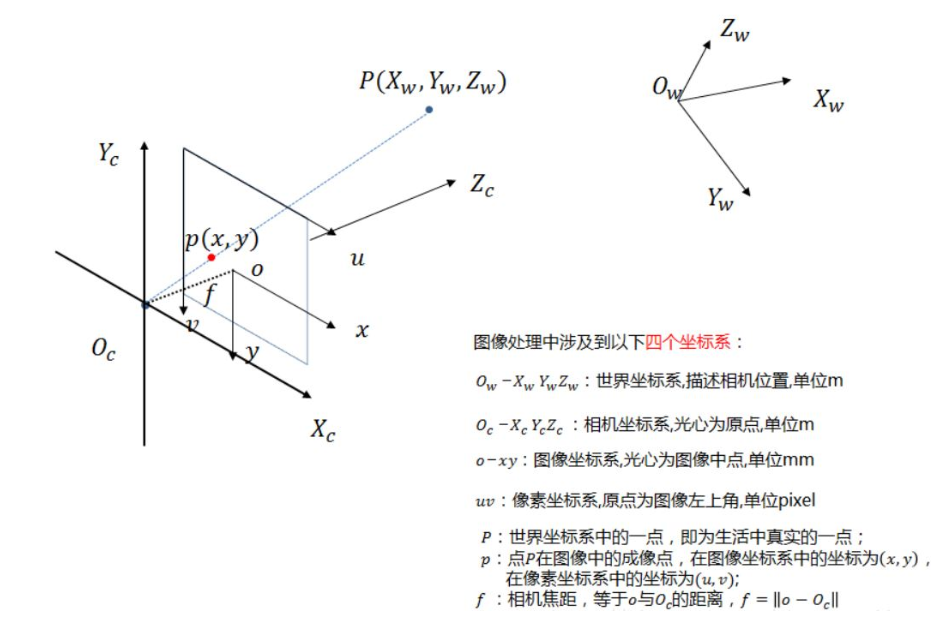
In binocular vision, the origin of the world coordinate system is usually located at the middle point of the X-axis of the left camera or the right camera or both. The next point is about the transformation of these coordinate systems. In other words, how a real object is imaged in an image.
World coordinate system and camera coordinate system
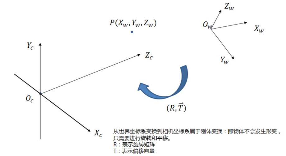
The rotation relationship from the world coordinate system to the camera coordinate system along different coordinate axes is as follows: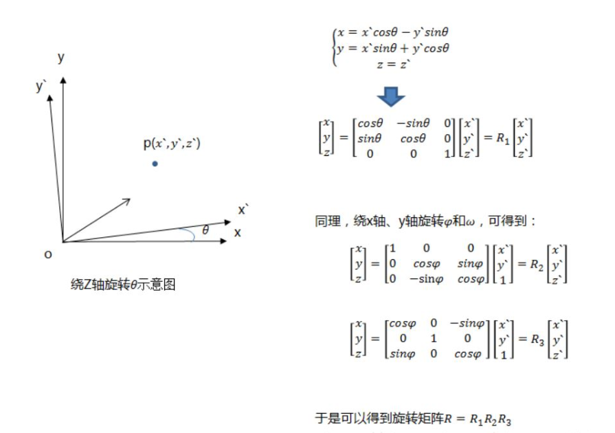
With the translation matrix, the coordinates of point P in the camera coordinate system can be obtained:
Camera coordinate system and image coordinate system
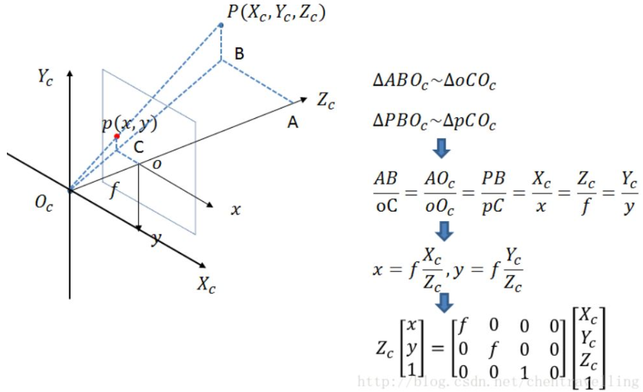
At this time, the unit of projection point p is still mm, not pixel, which needs to be further converted to pixel coordinate system.
Image coordinate system and pixel coordinate system
Pixel coordinate system and image coordinate system are on the imaging plane, but their origin and measurement units are different. The origin of the image coordinate system is the intersection of the camera optical axis and the imaging plane, usually the midpoint of the imaging plane or the principle point. The unit of image coordinate system is mm, which belongs to physical unit, while the unit of pixel coordinate system is pixel. We usually describe a pixel point in several lines and columns. So the conversion between them is as follows: dx and dy represent how many mm each column and row of a pixel represents respectively. dx and dy vary according to the resolution of different cameras.
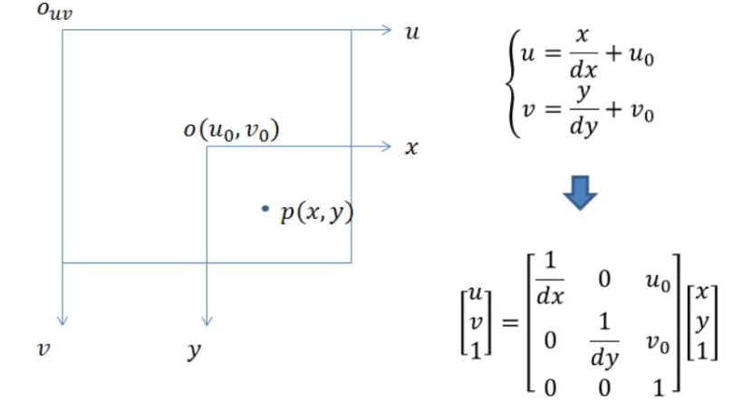
Then through the transformation of the following four coordinate systems, we can get the transformation of a point from the world coordinate system to the pixel coordinate system.

There are the following relationships among the four coordinate systems (matrix left multiplication in turn):
3. Internal and external parameter matrix of camera
Camera internal parameters are parameters related to its own characteristics, such as camera focal length, pixel size, etc;
Camera external parameters are parameters in the world coordinate system, such as camera position, rotation direction, etc.
In question 2, the conversion formula of the world coordinate system to the image pixel coordinate system has been derived in detail.
In this formula, fx, fy, u0 and v0 are only related to camera internal parameters, so matrix M1 is called internal parameter matrix.
 Where F X = f / DX and f y = f / dy are called the normalized focal length on the x-axis and y-axis respectively;
 f is the focal length of the camera, and dX and dY represent the size of the unit pixel on the x-axis and y-axis of the sensor, respectively.
 u0 and v0 represent the optical center, that is, the intersection of the camera optical axis and the image plane, which is usually located at the image center, so its value is usually half of the resolution.
Now take Canon 70d camera as an example to solve its internal parameter matrix:
Focal length f = 50mm resolution: 1920 × 1080 sensor size: 22.5 × 15 mm
According to the above definitions:
u0 = 1920/2= 960                v0 = 1080/2 = 540
dx = 22.5/1920 =0.01171875             dy = 15/1080 = 0.013889
fu = f/dx =  4266.667                 fv = f/dy = 3599.9712
4. Solving relative pose by linear method
Relative pose measurement based on spatial multi-point
Obtain camera internal parameters and distortion coefficients through camera calibration or camera self parameter calculation to establish the equation for converting the world coordinate system to pixel coordinate system. The purpose is to solve the rotation vector and translation vector of the external parameter matrix through the transformation of the equation group, eliminate the third dimension coordinates, and finally get a formula for rotation vector and translation vector. When there are six or more characteristic points and they are not coplanar, a matrix group about rotation vector and translation vector can be solved by QR decomposition of matrix, and the final rotation matrix and translation matrix can be obtained. Finally, the rotation angle is calculated by the rotation matrix, so that the camera coordinate system and the world coordinate system are completely parallel. Note: in the process of implementation, the solvePnP method is generally used for calculation. The input parameters are: 3D points of the target coordinate system, coordinates of image plane points, parameters in the camera, distortion coefficient. Finally, the rotation vector and translation vector can be obtained
Enter information:
The internal parameters of the camera are the coordinates of feature points (non coplanar, > = 6) in the target coordinate system (3D) and the phase plane coordinate system (2D).
Output information:
The position and attitude of the target coordinate system relative to the camera coordinate system.
Relative pose measurement based on plane multi feature points
Obtain camera internal parameters and distortion coefficients through camera calibration or camera self parameter calculation to establish the equation for converting the world coordinate system to pixel coordinate system. The purpose is to solve the rotation vector and translation vector of the external parameter matrix through the transformation of the equation group, eliminate the third dimension coordinates, and finally get a formula for rotation vector and translation vector. When there are four or more characteristic points and they are not coplanar, a matrix group about rotation vector and translation vector can be solved by QR decomposition of matrix, and the final rotation matrix and translation matrix can be obtained. Finally, the rotation angle is calculated by the rotation matrix, so that the camera coordinate system and the world coordinate system are completely parallel. Note: in the process of implementation, the solvePnP method is generally used for calculation. The input parameters are: 3D points of the target coordinate system, coordinates of image plane points, parameters in the camera, distortion coefficient. Finally, the rotation vector and translation vector can be obtained
Enter information:
Camera parameters feature points on multiple planes (> = 4) in target coordinate system (3D) and phase plane coordinate system (2D) coordinates
Output information:
The position and attitude of the target coordinate system relative to the camera coordinate system.
5. Zhang's calibration method
Input condition
The image data of multiple pose s of the target object, generally at least 10.
The coordinates of 3D points and image plane points in the target coordinate system are obtained through image data.
Output
Parameter matrix in camera

Distortion coefficient

Rotation variable

Translation variables
Main steps
Set calibration board
 Rotate the calibration board or camera to collect different pose s of the calibration board image
 For a post, calculate the homography matrix (similar to M matrix)
There are more than three posses, and the parameters of linear camera are calculated according to each homography matrix
 Using nonlinear optimization method to calculate nonlinear parameters
 Finally, the camera parameters, matrix distortion coefficient, rotation and translation variables of each image are obtained.
Code practice
Camera calibration
1. Use the checkerboard pattern and the camera you can find (laptop or desktop camera, mobile camera, etc.) to complete camera calibration, and give the credibility analysis of the results. (implemented with Python openCV)
1.1.2 step1 preparation
Equipment used in this operation:
(1) Self made A4 paper size calibration board (10 x 7 black and white chessboard, chessboard 13mm x 13mm)
(2) One ordinary mobile phone (2448 x 3264 pixels, vertical shooting)
12 photos in total
1.1.3 step 2 input data acquisition
The chessboard is made up of 10x8 squares, but the internal corners (excluding the outermost corners, otherwise an error will be reported) are read by the relevant API, so it is 9X6. According to the calculation formula of pixel coordinates and 3-D world coordinate system correlation matrix:
The above matrix relationship is abbreviated as:
I = M1M2W
According to Zhang's calibration method, by bringing in multiple corner Matrix I and world coordinate point W (Z=0, the default picture is in the plane of X and Y axes, reduce variables), we can reverse calculate the variables in camera inner matrix M1 and camera outer matrix M2=[R|T]. At the same time, the relevant distortion parameter matrix will be obtained.
Therefore, only the world coordinate W of the actual picture and the corresponding corner coordinate matrix I need to be obtained. Corner coordinates are roughly extracted by findcheckboardcorners, and then sub-pixel points are generated by using cornerSubPix; world coordinate points are set to Z=0 by default, and generated once according to the corner points of chessboard from left to right
(0,0,0), (113,0,0), (213,0,0) ,.
(13,0,0),(13,113,0), (13,213)...
...
Note: if you do not know the actual size of the chessboard, you can set it to
(0,0,0), (1,0,0), (2,0,0) ,..., (8,5,0)
The inner parameter matrix M1 of the camera is the same, but the outer parameter M2 is different.
#coding:utf-8
import cv2
import numpy as np
import glob
from tqdm import tqdm

#Define chessboard size: note that here is the number of internal row and column corners, excluding the outermost two columns, otherwise an error will occur
chessboard_size = (9,6)

# Generate a 54 × 3 matrix to save the 3D coordinates of 9 * 6 internal corners in the chessboard, that is, the coordinates of the object points
objp = np.zeros((np.prod(chessboard_size),3),dtype=np.float32)
# The xy coordinate points of the object are generated by np.mgrid, and the size of each chessboard is 130mm
# Finally, objp with z=0 is (0,0,0), (1 * 13,0,0), (2 * 13,0,0)
objp[:,:2] = np.mgrid[0:chessboard_size[0], 0:chessboard_size[1]].T.reshape(-1,2)*13

# print("object is %f", objp)

# Define an array to hold the monitored points
obj_points = []  # Save 3D points of world coordinate system
img_points = []  # Save 2D points of picture coordinate system


# Set termination condition: 30 iterations or change < 0.001
criteria = (cv2.TERM_CRITERIA_EPS + cv2.TERM_CRITERIA_MAX_ITER, 30, 0.001)

# Read all pictures in the directory
calibration_paths = glob.glob('./calibaration/*.jpg')

# To display conveniently, use tqdm to display the progress bar
for image_path in tqdm(calibration_paths):
    # Read pictures
    img = cv2.imread(image_path)
    # image binaryzation
    gray = cv2.cvtColor(img, cv2.COLOR_BGR2GRAY)

    # Find the position of the inner corner of the chessboard
    ret, corners = cv2.findChessboardCorners(gray, chessboard_size, None)

    if ret == True:
        obj_points.append(objp)
        # Sub-pixel corner detection, in corner detection, accurate corner position
        corners2 = cv2.cornerSubPix(gray, corners, (5, 5), (-1, -1), criteria)
        img_points.append(corners2)

        # Mark corner points in the drawing to facilitate viewing results
#         img = cv2.drawChessboardCorners(img, chessboard_size, corners2, ret)
#         img = cv2.resize(img, (400,600))
#         cv2.imshow('img', img)
#         cv2.waitKey(0)

cv2.destroyAllWindows()
print("finish all the pic count")
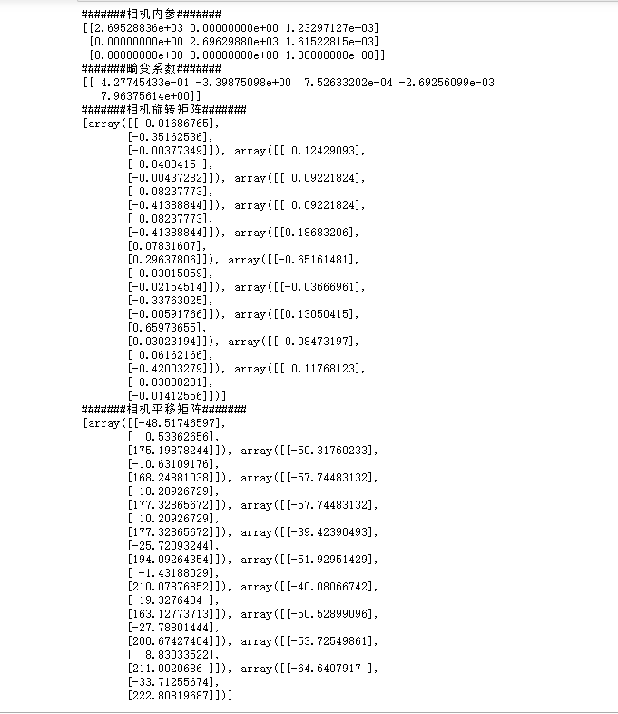
1.1.4 step 3 camera parameter acquisition 
The camera related internal parameters (fx, fy,u0, v0) [here alpha=0, may slightly deviate], external parameters (R,T), distortion parameters (k1,k2,p1,p2,s1,s2) can be obtained through calibrateCamera
# Camera calibration
ret, mtx, dist, rvecs, tvecs = cv2.calibrateCamera(obj_points, img_points, gray.shape, None, None)

# Display and save parameters
print("#######Camera internal reference#######")
print(mtx)
print("#######Distortion coefficient#######")
print(dist)
print("#######Camera rotation matrix#######")
print(rvecs)
print("#######Camera translation matrix#######")
print(tvecs)
np.savez('C.npz', mtx=mtx, dist=dist, rvecs=rvecs, tvecs=tvecs) #Use MTX, dist, rvecs and tvecs to name arrays respectively
1.1.5 Step3 camera parameter acquisition (unnecessary)
You can choose to use a picture to see the picture effect after removing the distortion. Before that, we need to use getoptimal new camera matrix to regenerate the camera matrix, so as to reduce the loss of effective pixels of the original image. It has a parameter alpha, called scale factor, which takes 0-1. If alpha=0, the original image will lose the most effective pixels; if alpha=1, all pixels in the original image can be preserved. getOptimalNewCameraMatrix also returns an image ROI that can be used to crop the results.
See calibresult.jpg for final effect
# Use a picture to see the effect after distortion removal
img2 = cv2.imread('./calibaration/left_01.jpg')
print("orgininal img_point  array shape",img.shape)
# img2.shape[:2] takes the picture height and width;
h,  w = img2.shape[:2]
print("pic's hight, weight: %f,  %f"%(h, w))
# img2.shape[:3] take the height, width and channel of the picture
# h,  w ,n= img2.shape[:3]
# print("PIC shape", (h, w, n))


newcameramtx, roi = cv2.getOptimalNewCameraMatrix(
    mtx, dist, (w, h), 1, (w, h))  # Free scale parameters

dst = cv2.undistort(img2, mtx, dist, None, newcameramtx)

# Crop the image according to the ROI area in front
x,y,w,h = roi
dst = dst[y:y+h, x:x+w]
cv2.imwrite('calibresult.jpg', dst)
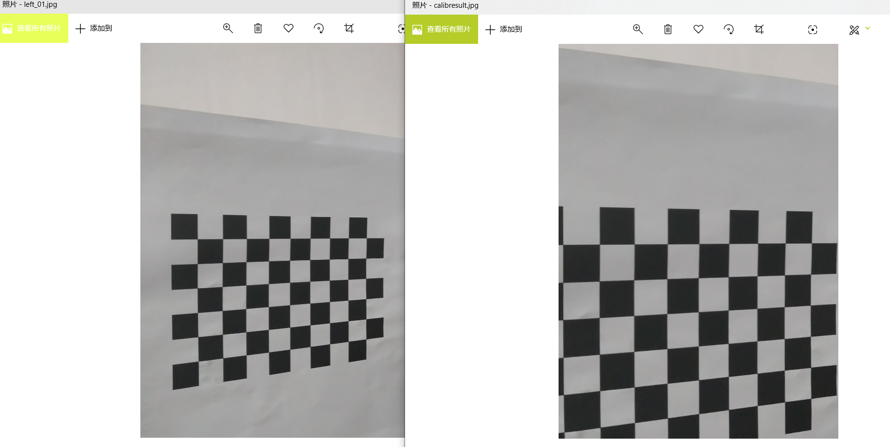
The distortion is relatively small, and the image is also cropped after elimination
1.1.6 step 4 re projection error
The re projection error is a reference index to judge the accuracy of distortion parameters. The closer it is to 0, the better. Given the distortion matrix, rotation matrix and translation matrix, the object point coordinates are first transformed to image point coordinates, which can be realized by using the projectPoints function. Then calculate the l2 norm average value of the transformed image points and the corner coordinates we detected before (that is, average by adding and square).
# Calculate the average re projection error of all pictures
total_error = 0
for i in range(len(obj_points)):
    img_points2, _ = cv2.projectPoints(obj_points[i], rvecs[i], tvecs[i], mtx, dist)
    error = cv2.norm(img_points[i], img_points2, cv2.NORM_L2)/len(img_points2)
    total_error += error
print("total error: {}".format(total_error/len(obj_points)))
1.1.7 1.3 image data result analysis 
Relevant parameters of mobile phone are as follows:
	f = 4
	Resolution: 2448 x 3264
	The size of a single cell phone pixel is about Δ x = Δ y: 1.4um
By manual calculation, relevant parameters are predicted as follows:
 u0'=2448/2=1224,
 v0'=3264/2=1632
 fx'=fy'=f/Δx=4/1.4*10^3 = 2857.14286
The related internal parameters are calculated by step1-step4
fx = 2.69528836e+03
fy = 2.69629880e+03
u0 = 1.23297127e+03
v0 = 1.61522815e+03
The related internal parameter calculation is generally within the normal error, which is more reasonable.
Camera projection
- On the basis of 1, using the same camera, the chessboard is fixed about 1m in front, and then the relative pose is estimated by linear method, then the rationality of the result is evaluated.
Experimental conditions:
Or the same camera: (2448 x 3264, portrait)
Place the self-made calibration plate (10 x 7, grid size 13mm) at about 1000mm (1m), and take a picture.
Theoretical principle:
It can be seen from the derivation process that the rotation variable R and displacement variable t are the rotation and translation variables from the world coordinate system to the camera coordinate system. When the calibration plate (xy plane of the world coordinate system) and the camera plane (xy plane of the camera coordinate system) are approximately parallel, their z axis is approximately parallel, so the displacement distance of T on the z axis is approximately equal to the actual distance of both in the real scene, that is, approximately equal to 1000mm.
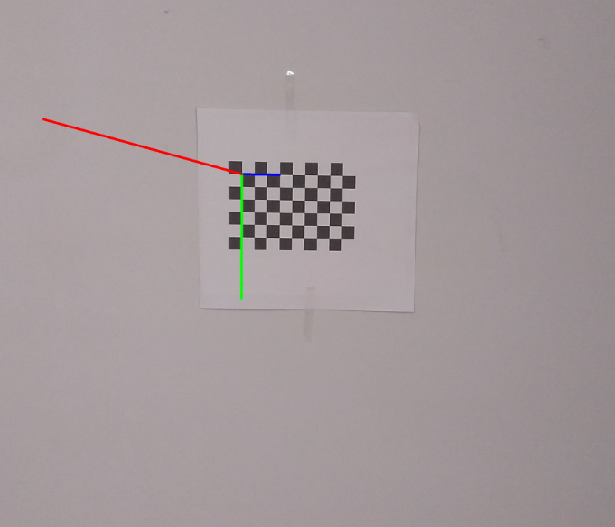
In addition, by selecting three points in the world coordinate system in advance and using 3D - > 2D projection, the mapping image of the relevant points can be drawn at the origin of the image coordinate system, and the correctness of the relative pose estimation of the relevant linear method can also be explained.
import cv2
import numpy as np
from math import degrees as dg

# Loading the internal and external parameter matrix of camera calibration
with np.load('C.npz') as X:
    mtx, dist, _, _ = [X[i] for i in ('mtx', 'dist', 'rvecs', 'tvecs')]

 print(mtx, dist)

#Define chessboard size
chessboard_size = (9,6)

# Object position matrix in world coordinate system (Z=0)
objp = np.zeros((np.prod(chessboard_size),3),dtype=np.float32)
objp[:,:2] = np.mgrid[0:chessboard_size[0], 0:chessboard_size[1]].T.reshape(-1,2)*13

# Pixel coordinates
test_img = cv2.imread("./test/100cm.jpg")
gray = cv2.cvtColor(test_img, cv2.COLOR_BGR2GRAY)


# Find the corner coordinates of image plane points
ret, corners = cv2.findChessboardCorners(gray, chessboard_size, None)

if ret:
    _, R, T, _, = cv2.solvePnPRansac(objp, corners, mtx, dist)
    print("Rotation vector",R)
    print("Translation vector",T)

sita_x = dg(R[0][0])
sita_y = dg(R[1][0])
sita_z = dg(R[2][0])

print("sita_x is  ", sita_x)
print("sita_y is  ", sita_y)
print("sita_z is  ", sita_z)
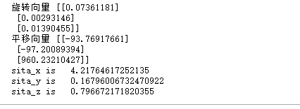
Analysis:
According to the above calculation:
The movement displacement of displacement variable along z axis is 960.23210427, along x,y,z rotation angle (angle system) is 4.21 degrees, 0.167 degrees, 0.796 degrees respectively;
It can be seen that there is basically no rotation between the world coordinates and the camera coordinates, and the x,y,z axes are basically in a parallel state, all of which are realized by translation. Moreover, the distance between the world coordinate and the image polar coordinate is 960.232, which is basically consistent with the actual 1000mm. So the relative postures are basically calculated correctly.
2.2 3D - > 2D projection
import cv2
import numpy as np
import glob

# Loading camera calibration data
with np.load('C.npz') as X:
    mtx, dist, _, _ = [X[i] for i in ('mtx', 'dist', 'rvecs', 'tvecs')]


def draw(img, corners, imgpts):
    """
    //Draw a three-dimensional axis on the picture
    :param img: Original picture data
    :param corners: Image plane point coordinate point
    :param imgpts: Coordinates of 3D points projected on 2D image plane
    :return:
    """
    # corners[0] is the coordinate origin of image coordinate system; imgpts[0]-imgpts[3] is the coordinate of 3D world coordinate system point projected on 2D world
    corner = tuple(corners[0].ravel())
    # Draw three lines in three directions
    cv2.line(img, corner, tuple(imgpts[0].ravel()), (255, 0, 0), 5)
    cv2.line(img, corner, tuple(imgpts[1].ravel()), (0, 255, 0), 5)
    cv2.line(img, corner, tuple(imgpts[2].ravel()), (0, 0, 255), 5)
    return img

#Define chessboard size
chessboard_size = (9,6)

# Initialize 3D point of target coordinate system
objp = np.zeros((np.prod(chessboard_size),3),dtype=np.float32)
objp[:,:2] = np.mgrid[0:chessboard_size[0], 0:chessboard_size[1]].T.reshape(-1,2)

# Initialize 3D coordinate system
axis = np.float32([[3, 0, 0], [0, 10, 0], [0, 0, -50]]).reshape(-1, 3)  # Axis of coordinates

# Load and package all picture data
images = glob.glob('test/100cm.jpg')
for fname in images:
    img = cv2.imread(fname)
    gray = cv2.cvtColor(img, cv2.COLOR_BGR2GRAY)
    # Find the coordinate point of image plane point
    ret, corners = cv2.findChessboardCorners(gray, chessboard_size, None)
    if ret:
        # PnP calculates the rotation vector and translation vector
        _, rvecs, tvecs, _ = cv2.solvePnPRansac(objp, corners, mtx, dist)
        print("Rotation variable", rvecs)
        print("Translation variables", tvecs)
        # Calculate the coordinates of 3D points projected on 2D image plane
        imgpts, jac = cv2.projectPoints(axis, rvecs, tvecs, mtx, dist)
        # Show the coordinates on the picture
        img = draw(img, corners, imgpts)
        cv2.imwrite("3d_2d_project.jpg",img)


cv2.destroyAllWindows()
In the image, the coordinate system of the relevant 3D projection is as follows: