Preface
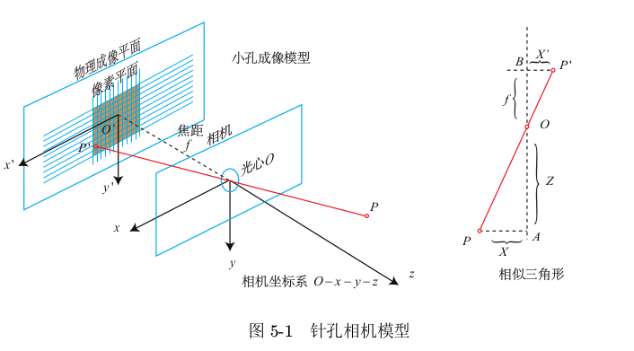
- The process of mapping coordinate points (in meters) in 3D world to 2D image plane (in pixels) can be described by a geometric model. There are many kinds of models, the simplest of which is called pinhole model.
- In order to get a good imaging effect, we add a lens in front of the camera. The addition of the lens will have a new impact on the propagation of light in the imaging process: first, the shape of the lens itself will affect the propagation of light; second, in the process of mechanical assembly, the lens and the imaging plane cannot be completely parallel, which will also change the position of the light when it is projected through the lens to the imaging plane.
- The distortion caused by the lens shape is called radial distortion. In pinhole model, whether a line is projected on the pixel plane or a line. However, in the actual photos, the lens of the camera often makes a straight line in the real environment become a curve in the pictures. The closer to the edge of the image, the more obvious the phenomenon is. Because the lens manufactured in practice is usually centrosymmetric, the irregular distortion is usually radially symmetric. They are mainly divided into two categories, barrel distortion and pillow distortion.
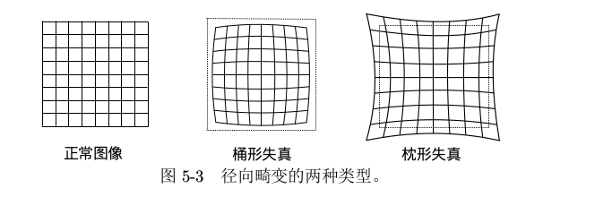
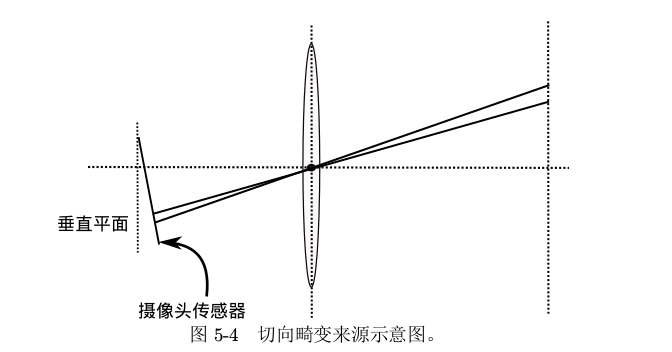
- Barrel distortion is due to the decrease of image magnification with the increase of distance from optical axis, while pillow distortion is just the opposite. In these two kinds of distortions, a line passing through the center of the image and having an intersection with the optical axis can keep its shape unchanged. In addition to the radial distortion caused by the shape of the lens, the tangential distortion will also be introduced because the lens and the imaging plane cannot be strictly parallel during the assembly process of the camera.
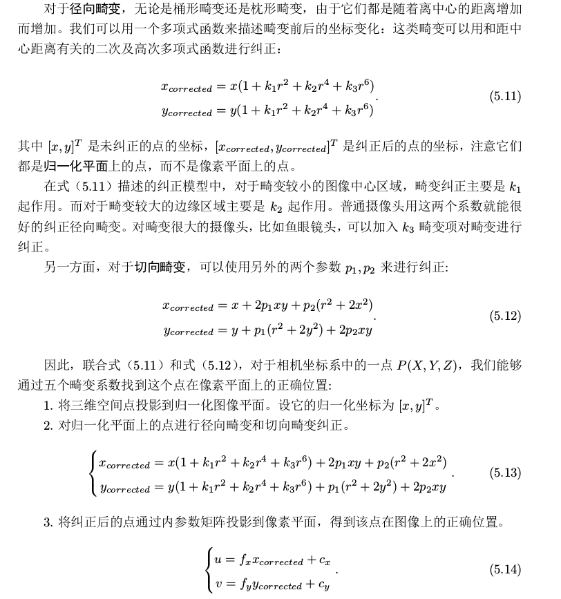
In practical application, the correction model can be selected flexibly, such as only K 1, p 1, P 2.
All of the above are based on Gao Xiang's vision SLAM14 from theory to practice.
- In a word, due to the distortion of the camera, it is necessary to calibrate the image to reduce the error.
Reference books:
- Gao Xiang's vision SLAM14: from theory to practice
Reference link:
- https://blog.csdn.net/AdamShan/article/details/78712120
Environmental Science
- Ubuntu16.04
- pycharm
- opencv
- python3.5
Camera calibration
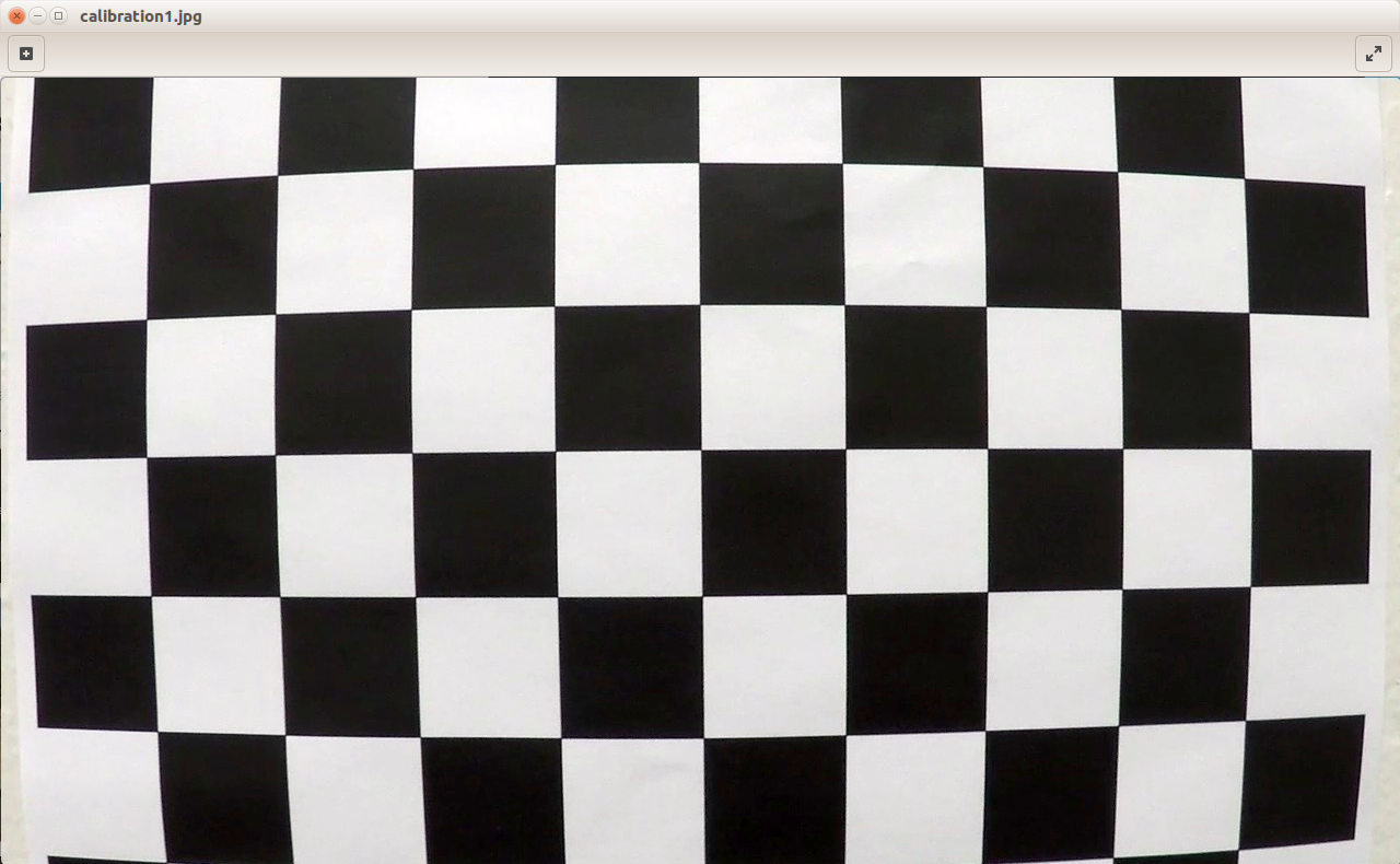
- Consider a picture of the chessboard first
Original graph
You can see that the straight line at the edge of the picture is distorted badly.
Code
# Camera calibration

import cv2

# First, read the image and turn it into a grayscale image
img = cv2.imread('./camera_cal/calibration1.jpg')
gray = cv2.cvtColor(img, cv2.COLOR_BGR2GRAY)

# cv2.imshow("img",img)
# cv2.imshow("gray",gray)

# Use OpenCV's cv2.findChessboardCorners() function to find out the diagonal in the checkerboard (that is, the coordinates of the black and white points in the picture),
# At the same time, use cv2.drawChessboardCorners() to draw it out

# Cv2.findcheckboardcorners parameter patternSize (9,5) - the number of intersections of each row and column in the chessboard
# Take (9,5) and print the cores to get the output. Otherwise, it's None,
# The reason is that the imported pictures. / camera_cal/calibration1.jpg count the number of next intersections, 9 in a row and 5 in a column
# The reason why Adam chose (9,6) in his blog is that his graph is different from mine. If you count it carefully, you can find that his graph is indeed nine rows, six columns and six corners
# It turns out that (9,4) is OK, as long as the size is smaller than the number of intersections in the picture

# For function analysis, see the official website https://docs.opencv.org/3.3.0/dc/dbb/tutorial'py'calibration.html
# It returns the corner points and retval which will be True if pattern is obtained.
# These corners will be placed in an order (from left-to-right, top-to-bottom)
ret, corners = cv2.findChessboardCorners(gray, (9, 5),None)
print(ret)
# print(corners)  # Intersection coordinates

if ret == True:
    img = cv2.drawChessboardCorners(img, (9, 5), corners, ret)

cv2.imshow("final",img)

cv2.waitKey()
cv2.destroyAllWindows()
- Printout
True
- Result diagram
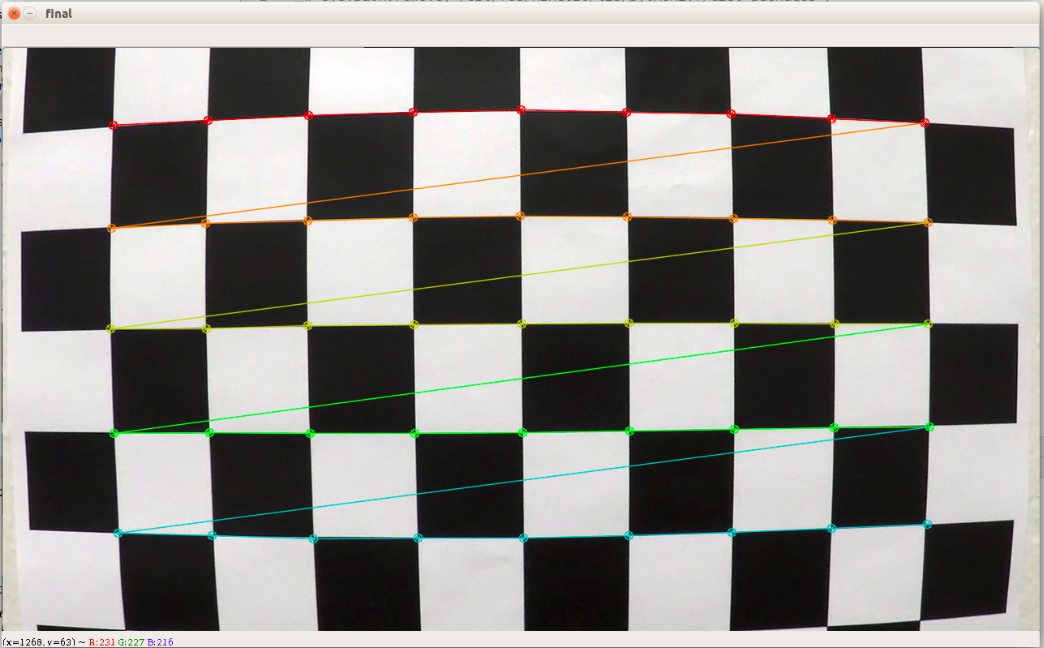
So far, it is just to find the intersection and mark it, and then it should be corrected. The relative positions of these diagonal points in the real world are constructed, and these positions are simplified to integer values.
The complete code is as follows:
# Camera calibration

import cv2
import numpy as np

# First, read the image and turn it into a grayscale image
img = cv2.imread('./camera_cal/calibration1.jpg')
gray = cv2.cvtColor(img, cv2.COLOR_BGR2GRAY)

# cv2.imshow("img",img)
# cv2.imshow("gray",gray)

# Use OpenCV's cv2.findChessboardCorners() function to find out the diagonal in the checkerboard (that is, the coordinates of the black and white points in the picture),
# At the same time, use cv2.drawChessboardCorners() to draw it out

# Cv2.findcheckboardcorners parameter patternSize (9,5) - the number of intersections of each row and column in the chessboard
# Take (9,5) and print the cores to get the output. Otherwise, it's None,
# The reason is that the imported pictures. / camera_cal/calibration1.jpg count the number of next intersections, 9 in a row and 5 in a column
# The reason why Adam chose (9,6) in his blog is that his graph is different from mine. If you count it carefully, you can find that his graph is indeed nine rows, six columns and six corners
# It turns out that (9,4) is OK, as long as the size is smaller than the number of intersections in the picture

# For function analysis, see the official website https://docs.opencv.org/3.3.0/dc/dbb/tutorial'py'calibration.html
# It returns the corner points and retval which will be True if pattern is obtained.
# These corners will be placed in an order (from left-to-right, top-to-bottom)
ret, corners = cv2.findChessboardCorners(gray, (9, 5),None)
# print(ret)
# print(corners)  # Intersection coordinates

if ret == True:
    img = cv2.drawChessboardCorners(img, (9, 5), corners, ret)

cv2.imshow("result",img)

# To construct the relative positions of these diagonal points in the real world, we simplify these positions to integer values
objp = np.zeros((5*9, 3), np.float32)
objp[:, :2] = np.mgrid[0:9, 0:5].T.reshape(-1, 2)

img_points = []
obj_points = []

img_points.append(corners)
obj_points.append(objp)

# Finally, we can use cv2.calibrateCamera() in OpenCV to get the distortion coefficient of the camera, which can be used to correct all subsequent images
image_size = (img.shape[1], img.shape[0])
#  It returns the camera matrix, distortion coefficients, rotation and translation vectors etc.
ret, mtx, dist, rvecs, tvecs = cv2.calibrateCamera(obj_points, img_points,image_size, None, None)

test_img = cv2.imread("./camera_cal/calibration3.jpg")
# The last parameter of cv2.undo is still the original camera matrix mtx
# You can also try to use cv2.getOptimalNewCameraMatrix() to optimize the camera matrix based on the free scaling parameters, and then bring in
undist = cv2.undistort(test_img, mtx, dist, None, mtx)

cv2.imshow("test_img",test_img)
cv2.imshow("undist",undist)

cv2.waitKey()
cv2.destroyAllWindows()
- The experimental results are roughly as follows. In the figure, Undo is the result after correction, and the bottom picture is test uuimg
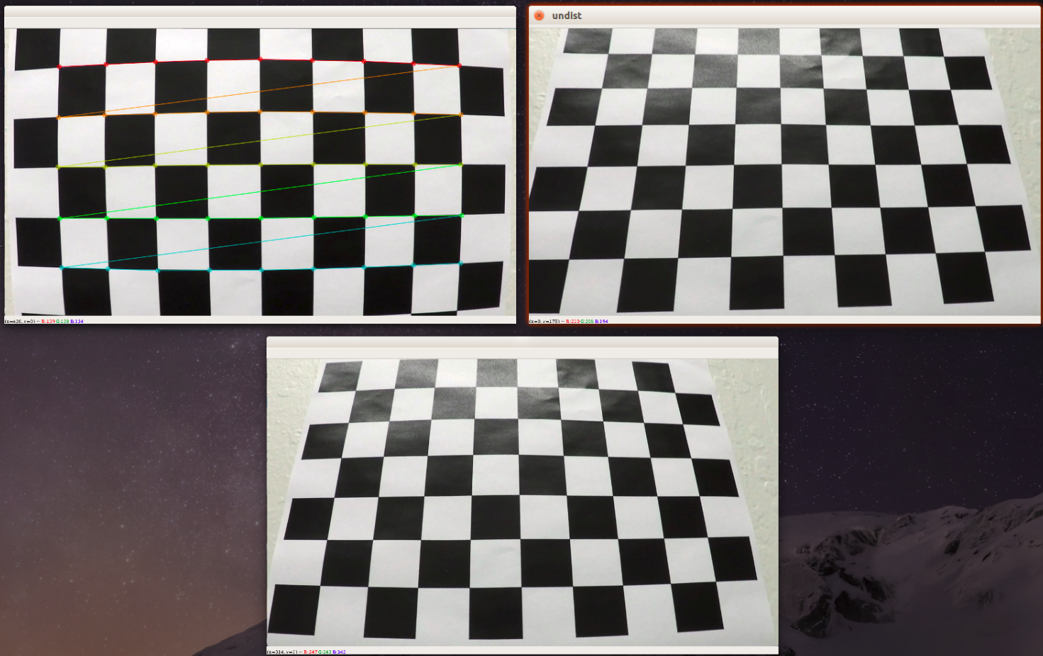
deficiencies:
- As mentioned above, only one chessboard image is considered here to get the camera's relevant distortion parameters. In fact, more than 10 chessboard images should have better effect, and then we can improve it. As written in the code, you can try to use cv2.getOptimalNewCameraMatrix() to optimize the camera matrix based on free scaling parameters.

