Development board: Wildfire domineering V1
Chip: stm32f103ZET6
Timer: TIM3
Output channel: CH3
GPIO: PB0
frequency
F = 72M / ((ARR+1)*(PSC+1))
Unit: Hz
Duty cycle
Duty_Cycle = (TIMx->CCRx) / ARR
Unit:%
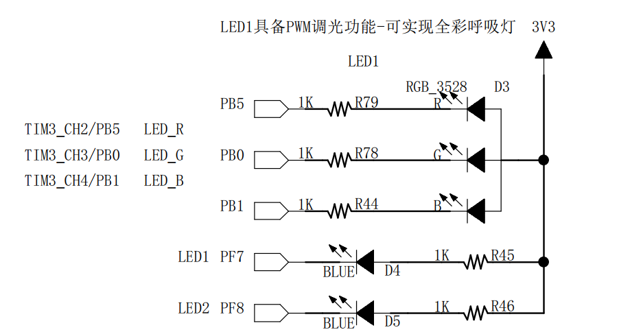
The following test is to observe the brightness change of LED small lamp by adjusting PWM duty cycle
Circuit
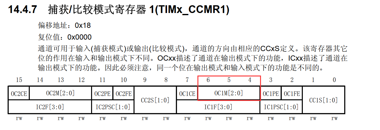
Output comparison
The output comparison mode is configured by bit OCxM[2:0] of register CCMRx
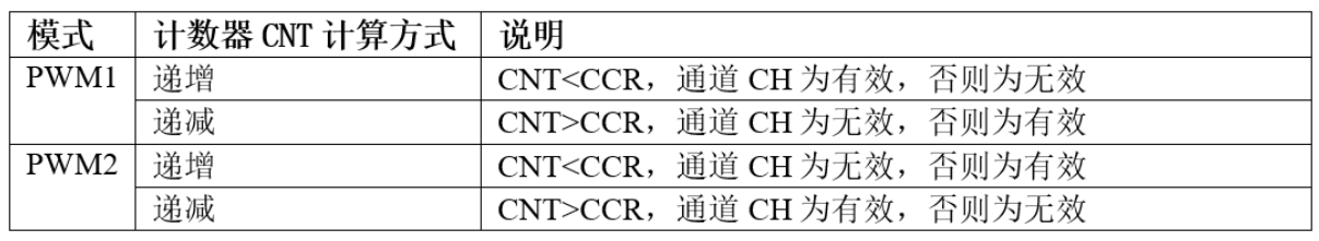
There are two PWM modes
Output comparison structure
typedef struct {
	uint16_t TIM_OCMode; // Compare output mode
	uint16_t TIM_OutputState; // Compare output enable
	uint16_t TIM_OutputNState; // Compare complementary output enable
	uint32_t TIM_Pulse; // pulse width
	uint16_t TIM_OCPolarity; // Output polarity
	uint16_t TIM_OCNPolarity; // Complementary output polarity
	uint16_t TIM_OCIdleState; // Compare output status in idle state
	uint16_t TIM_OCNIdleState; // Compare complementary output states in idle state
} TIM_OCInitTypeDef;
General timer output PWM only needs to configure some members
1,TIM_OCMode: compare the output mode selection. There are eight kinds in total. The commonly used ones are PWM1/PWM2. It sets the value of OCxM[2:0] bit of CCMRx register
2,TIM_OutputState: compare output enable to determine whether the final output comparison signal OCx is output through an external pin. It sets timx_ Value of CCxE/CCxNE bit of CCER register
3,TIM_OCPolarity: compare the output polarity. The optional OCx is high-level active or low-level active. It determines the effective level of the timer channel. It sets the value of the CCxP bit of the CCER register
Time base unit structure
typedef struct
{
	uint16_t TIM_Prescaler; // Prescaler
	uint16_t TIM_CounterMode; // Counting mode
	uint32_t TIM_Period; // Timer cycle
	uint16_t TIM_ClockDivision; // clock division
	uint8_t TIM_RepetitionCounter; // Repeat calculator
} TIM_TimeBaseInitTypeDef;
1,TIM_Prescaler: timer prescaler setting. The clock source is the timer counting clock CK through the prescaler_ CNT, which sets the value of the PSC register. The calculation formula is: counter clock frequency (fCK_CNT) is equal to fCK_PSC / (PSC[15:0] + 1), which can realize frequency division from 1 to 65536.
2,TIM_ Counter mode: timer counting mode, which can be set to count up, count down and center alignment. The advanced control timer allows you to select any one.
3,TIM_Period: timer cycle. In fact, it is to set the value of the automatic reload register ARR. ARR is the value to be loaded into the actual automatic reload register (i.e. shadow register), which can be set from 0 to 65535.
4,TIM_ClockDivision: clock division, set timer clock CK_ Frequency division ratio of int frequency to sampling clock frequency of dead band generator and digital filter. You can select 1, 2 and 4 frequency division.
5, TIM_ Repetition counter: repetition counter, only 8 bits, only exists in advanced timer
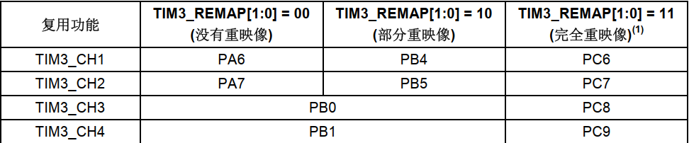
TIM3 reuse function remapping
Set duty cycle
//It can be used to change the duty cycle when PWM is output
void TIM_SetCompare1(TIM_TypeDef* TIMx, uint16_t Compare1);
void TIM_SetCompare2(TIM_TypeDef* TIMx, uint16_t Compare2);
void TIM_SetCompare3(TIM_TypeDef* TIMx, uint16_t Compare3);
void TIM_SetCompare4(TIM_TypeDef* TIMx, uint16_t Compare4);
The channel used in this experiment is CH3
So use the function
void TIM_SetCompare3(TIM_TypeDef\* TIMx, uint16_t Compare3);
code implementation
#include "bsp_GeneralTimer.h"

//GPIO for initialization
static void GENERALTIMER_GPIO_Config(void)
{
	GPIO_InitTypeDef   GPIO_InitStruct;

	RCC_APBxPeriphClockCmd(GENERALTIMER_CHANNEL_GPIO_CLOCK | RCC_APB2Periph_AFIO,ENABLE);  //Enable GPIO peripheral and AFIO multiplexing function clock

	GPIO_InitStruct.GPIO_Pin = GENERALTIMER_CHANNEL_GPIO_PIN;
	GPIO_InitStruct.GPIO_Mode = GPIO_Mode_AF_PP;
	GPIO_InitStruct.GPIO_Speed = GPIO_Speed_50MHz;

	GPIO_Init(GENERALTIMER_CHANNEL_GPIO_PORT,&GPIO_InitStruct);
}

//Initialize timer mode
static void GENERALTIMER_MODE_Config(void)
{
	//Time base
	TIM_TimeBaseInitTypeDef TIM_TimeBaseInitStruct;
	//Output comparison
	TIM_OCInitTypeDef TIM_OCInitStruct;

	GENERALTIMER_TIMx_CLOCK_FUN(GENERALTIMER_TIMx_CLOCK,ENABLE);

	//Configure time base unit
	TIM_TimeBaseInitStruct.TIM_Prescaler = GENERALTIME_PSC;  //Prescale Vlaue
	TIM_TimeBaseInitStruct.TIM_Period = GENERALTIME_Period;  //The value ARR of the automatic reload register cycle
	TIM_TimeBaseInitStruct.TIM_CounterMode = TIM_CounterMode_Up;  //Count up
	TIM_TimeBaseInitStruct.TIM_ClockDivision = TIM_CKD_DIV1;
	TIM_TimeBaseInitStruct.TIM_RepetitionCounter = 0;

	TIM_TimeBaseInit(GENERAL_TIMEx,&TIM_TimeBaseInitStruct);

	//Configure output comparison
	TIM_OCInitStruct.TIM_OCMode = TIM_OCMode_PWM2;           	//The PWM mode is configured as 2
	TIM_OCInitStruct.TIM_OutputState = TIM_OutputState_Enable;  //Output enable
	TIM_OCInitStruct.TIM_OCPolarity = TIM_OCPolarity_High; //Timer channel effective level

	TIM_OCxInit(GENERAL_TIMEx,&TIM_OCInitStruct);
	//Enable preload register
	TIM_OCxPreloadConfig(GENERAL_TIMEx,TIM_OCPreload_Enable);
	//Enable register
	TIM_Cmd(GENERAL_TIMEx,ENABLE);
}

void GENERALTIME_Config(void)
{
	GENERALTIMER_GPIO_Config();
	GENERALTIMER_MODE_Config();
}
. h file
#ifndef _BSP_GENERALTIMER_H
#define _BSP_GENERALTIMER_H

//TIM3 -> CH3   PB0

#include "stm32f10x.h"

//Timer GPIO
#define RCC_APBxPeriphClockCmd				RCC_APB2PeriphClockCmd
#define GENERALTIMER_CHANNEL_GPIO_CLOCK     RCC_APB2Periph_GPIOB
#define GENERALTIMER_CHANNEL_GPIO_PORT   	GPIOB
#define GENERALTIMER_CHANNEL_GPIO_PIN    	GPIO_Pin_0

//timer
#define GENERAL_TIMEx               		TIM3

#define GENERALTIMER_TIMx_CLOCK_FUN			RCC_APB1PeriphClockCmd
#define GENERALTIMER_TIMx_CLOCK     		RCC_APB1Periph_TIM3

#define GENERALTIME_PSC                     (0)
#define GENERALTIME_Period                  (100-1)

//PWM correlation function
#define TIM_OCxInit							TIM_OC3Init
#define TIM_OCxPreloadConfig				TIM_OC3PreloadConfig
#define TIM_SetComparex						TIM_SetCompare3


void GENERALTIME_Config(void);

#endif
The timer is initialized in the main function, and then you can use the function: TIM_. SetCompare3
Change the duty cycle to observe the brightness change of the small lamp
#include "bsp_GeneralTimer.h"


int main()
{
	GENERALTIME_Config();

	while (1)
	{
		TIM_SetComparex(TIM3,10);
	}
}
According to the fractional formula of duty cycle calculation, the duty cycle is: 10%