Project introduction
In this project, MAX32660 of Meixin is the main control chip, equipped with two kinds of sensors, which communicate with MCU through I2C, and display the sensor information and the perpetual calendar information calculated by RTC in MCU on the OLED screen, which can be used as the prototype of smart watch.
Use device
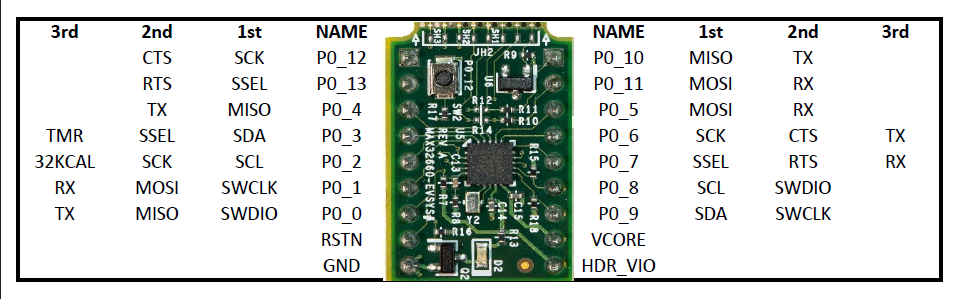
MAX32660-EVSYS
For details of MAX32660, see:
MAX32660, low power Arm Cortex-M4 FPU processor with FPU based microcontroller (MCU), 256KB Flash and 96KB SRAM. The debugging adapter based on MAX32625PICO has been installed on the motherboard; After programming, it can be removed directly. Its peripheral resources include:
- Maximum 14 channel GPIO
- Maximum two SPI
- One way I2S
- Maximum two-way UART
- Maximum two-way I2C
- Four channel standard DMA controller
- 3-way 32-bit timer
- Watchdog timer
- RTC 32.768kHz
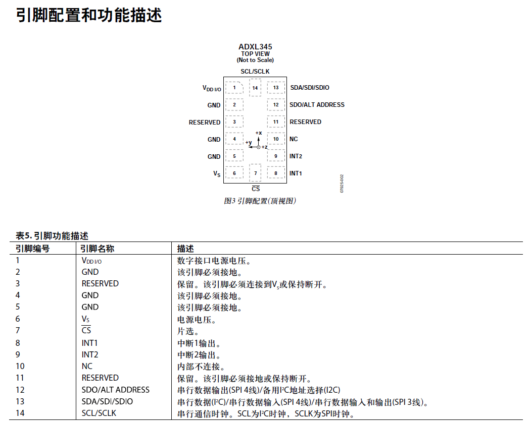
ADXL345 digital accelerometer
It is a small and thin ultra-low power 3-axis accelerometer with high resolution (13 bits) and a measurement range of ± 16 g. The digital output data is in 16 bit binary complement format and can be accessed through SPI(3-wire or 4-wire) or I2C digital interface. Static gravity acceleration can be measured in tilt detection applications, and dynamic acceleration caused by motion or impact can also be measured. Its high resolution (3.9 mg/LSB) can measure tilt angle changes of less than 1.0 °.
The device provides a variety of special detection functions:
- The active and inactive detection function detects whether there is movement by comparing the acceleration on any axis with the threshold set by the user;
- The knock detection function can detect single vibration and double vibration in any direction;
- The free fall detection function can detect whether the device is falling, etc.
For detailed function description, please refer to the website and documentation:
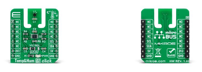
Temp&Hum 15 Click
Mikroe's plug and play sensor contains SHT40 to measure temperature and humidity information. I2C communication was originally used on LPCS55S69-EVK, which meets the basic sensor functions of smart watches.
For detailed function description, please refer to the website and documentation:
SS1306 driven 4-wire SPI 12864 OLED panel
The classic OLED screen, although the merchant said that SPI/I2C could be used, but the resistance had to be changed. Here, the 4-wire SPI communication mode was used. Originally, I wanted to go u8g2, but the transplantation was not very smooth.
Key codes and descriptions
SHT40 obtaining temperature and humidity information
For detailed description of SHT40 used in Click plug-in, see:
The merchant has provided the driver code corresponding to SHTx. See:
👉 GitHub
In the project, you only need to change the code of I2C reading and writing part according to the corresponding MCU. Here, use MAX32660, according to the help document, for sensitivity_ hw_ i2c_ Customized modification of I2C initialization, reading and writing functions in implementation. C (header file, etc. omitted):
// SHT40 and ADXL345 interrupt handler
void I2C0_IRQHandler(void)
{
    I2C_Handler(MXC_I2C0);
    return;
}

int16_t sensirion_i2c_select_bus(uint8_t bus_idx) {
    // IMPLEMENT or leave empty if all sensors are located on one single bus
    return STATUS_FAIL;
}

void sensirion_i2c_init(void)
{
    //Setup the I2C0
	int error = 0;
	const sys_cfg_i2c_t sys_i2c_cfg = NULL;

    //I2C_Shutdown(SHT40_I2C);
    if((error = I2C_Init(SHT40_I2C, I2C_FAST_MODE, &sys_i2c_cfg)) != E_NO_ERROR)
	{
        printf("Error initializing I2C0.(Error code = %d)\n", error);
		while(1);
    }
    NVIC_EnableIRQ(I2C0_IRQn);
}

/**
 * Release all resources initialized by sensirion_i2c_init().
 */
void sensirion_i2c_release(void) {
    // IMPLEMENT or leave empty if no resources need to be freed
}

int8_t sensirion_i2c_read(uint8_t address, uint8_t* data, uint16_t count)
{
	int error = 0;
	if((error = I2C_MasterRead(SHT40_I2C, (address << 1)|1, data, count, 0)) != count) {
        printf("Error reading%d\n", error);
        return error;
    }
	return 0;
}

int8_t sensirion_i2c_write(uint8_t address, const uint8_t* data, uint16_t count)
{
	int error = 0;
	if((error = I2C_MasterWrite(SHT40_I2C, (address << 1)|0, data, count, 0)) != count)
	{
        printf("Error writing %d\n", error);
        return error;
    }
	return 0;
}

void sensirion_sleep_usec(uint32_t useconds)
{
	mxc_delay(useconds);
}
In the main program, the measured value of temperature and humidity can be obtained through the following statements (the measured value has been processed):
int32_t temperature, humidity;
int8_t ret = 0;
ret = sht4x_measure_blocking_read(&temperature, &humidity);
	if (ret == STATUS_OK)
	{
		printf("measured temperature: %0.2f degreeCelsius, "
			   "measured humidity: %0.2f percentRH\n", temperature / 1000.0f, humidity / 1000.0f);
	}
	else
	{
		printf("error reading measurement\n");
	}
ADXL get inclination information
There are a lot of information about ADXL345 on the Internet, which can be modified according to the service history of MCU such as STM32. Modify I2C initialization, read / write, etc.:
#define ADXL345_I2C MXC_I2C0
int ADXL345_Init(void)
{
uint8_t error;
//I2C_Shutdown(ADXL345_I2C);
if((error = I2C_Init(ADXL345_I2C, I2C_FAST_MODE, NULL)) != E_NO_ERROR)
{
printf("Error initializing I2C0.(Error code = %d)\n", error);
while(1);
}
NVIC_EnableIRQ(I2C0_IRQn);
if(ADXL345_RD_Reg(DEVICE_ID) == 0xE5) //Read device ID
{
ADXL345_WR_Reg(INT_ENABLE, 0x00);
ADXL345_WR_Reg(DATA_FORMAT, 0x0B); //Low level interrupt output, 13 bit full resolution, right alignment of output data, 16g range
ADXL345_WR_Reg(BW_RATE, 0x0C); //The data output speed is 400Hz
ADXL345_WR_Reg(POWER_CTL, 0x38); //Link enable, automatic sleep, measurement mode
ADXL345_WR_Reg(OFSX, 0x00);
ADXL345_WR_Reg(OFSY, 0x00);
ADXL345_WR_Reg(OFSZ, 0x00);
return E_NO_ERROR;
}
return 1;
}
uint8_t ADXL345_Write_Len(uint8_t addr,uint8_t reg,uint8_t len,uint8_t *buf)
{
uint8_t txdata[16], error;
uint8_t i;
txdata[0] = reg;
for(i = 1; i < len+1; i++){
txdata[i] = buf[i-1];
}
if((error = I2C_MasterWrite(ADXL345_I2C, (addr << 1)|0, txdata, len+1, 0)) != len+1)
{
printf("Error writing %d in ADXL345_Write_Len!\n", error);
return error;
}
return 0;
}
uint8_t ADXL345_Read_Len(uint8_t addr, uint8_t reg, uint8_t len, uint8_t *buf)
{
uint8_t res;
uint8_t error = 0;
if((error = I2C_MasterWrite(ADXL345_I2C, (addr << 1)|0, ®, 1, 0)) != 1)
{
printf("Error writing %d in ADXL345_Read_Len!\n", error);
return error;
}
if((error = I2C_MasterRead(ADXL345_I2C, (addr << 1)|1, buf, len, 0)) != len)
{
printf("Error reading %d in ADXL345_Read_Len!\n", error);
return error;
}
return 0;
}
uint8_t ADXL345_WR_Reg(uint8_t reg,uint8_t data)
{
uint8_t error;
uint8_t txdata[2];
txdata[0] = reg;
txdata[1] = data;
if((error = I2C_MasterWrite(ADXL345_I2C, ADXL345_WRITE, txdata, 2, 0)) != 2)
{
printf("Error writing %d in ADXL345_WR_Reg!\n", error);
return error;
}
return 0;
}
uint8_t ADXL345_RD_Reg(uint8_t reg)
{
uint8_t error;
uint8_t data;
if((error = I2C_MasterWrite(ADXL345_I2C, ADXL345_WRITE, ®, 1, 0)) != 1)
{
printf("Error writing %d in ADXL345_RD_Reg!\n", error);
return error;
}
if((error = I2C_MasterRead(ADXL345_I2C, ADXL345_READ, &data, 1, 0)) != 1)
{
printf("Error reading %d in ADXL345_RD_Reg!\n", error);
return error;
}
return data;
}
It should be noted that the initialization design needs to modify the corresponding functions according to the ADXL345 manual. Next, write the function of measuring inclination:
void ADXL345_PROC(float *angle_x, float *angle_y, float *angle_z)
{
    short x, y, z;
	float x_acc_ad, y_acc_ad, z_acc_ad;
    float x_angle, y_angle, z_angle;
    ADXL345_Read_Average(&x, &y, &z, 10);  //Read the acceleration values in X, y and Z directions for 10 times in total

	printf("Acc of X-axis: %.1f m/s2\n", x*1.0/256*9.8);
	printf("Acc of Y-axis: %.1f m/s2\n", y*1.0/256*9.8);
	printf("Acc of Z-axis: %.1f m/s2\n", z*1.0/256*9.8);

	x_acc_ad = x*1.0/32;
	y_acc_ad = y*1.0/32;
	z_acc_ad = z*1.0/32;

    x_angle = ADXL345_Get_Angle(x_acc_ad, y_acc_ad, z_acc_ad, 1);
    y_angle = ADXL345_Get_Angle(x_acc_ad, y_acc_ad, z_acc_ad, 2);
    z_angle = ADXL345_Get_Angle(x_acc_ad, y_acc_ad, z_acc_ad, 0);

	printf("Angle of X-axis: %.1f degree\n", x_angle);
	printf("Angle of Y-axis: %.1f degree\n", y_angle);
	printf("Angle of Z-axis: %.1f degree\n", z_angle);
    *angle_x = x_angle;
	*angle_y = y_angle;
	*angle_z = z_angle;
}
First calculate the acceleration of X, Y and Z axes, then calculate the inclination, and print both information to the serial port. The value obtained by the algorithm given in the sensory history is incorrect. The above additional calibration calculation part is referred to as follows:
👉 Station B: ADXL345 accelerometer tutorial [how to Mechatronics]
It should be noted again that in the main program, auto adjust is required after initialization. At this time, ADXL345 chip needs to be leveled as the benchmark, such as:
uint8_t xval = 0, yval = 0, zval= 0;
while(ADXL345_Init() != E_NO_ERROR)
{
	printf("ADXL345 initialization failed\n");
       mxc_delay(MXC_DELAY_SEC(1));
}
ADXL345_AUTO_Adjust(&xval, &yval, &zval);
The inclination value can be obtained by adding the following code:
float angle_x, angle_y, angle_z;
ADXL345_PROC(&angle_x, &angle_y, &angle_z);
RTC perpetual calendar
RTC inside MCU is used to realize two functions:
- Perpetual calendar, initialize the current time (month, day, week, hour, minute and second), display the time on the OLED screen and refresh the time every second;
- It is automatically set to update the tilt angle, temperature and humidity information every minute, and display these information on the OLED screen.
The RTC initialization and interrupt service function code refers to the RTC routine provided by MAXIM. For the function for calculating the current time (GetNowTime(), modified), see:
In the RTC initialization function, record the number of seconds at the beginning; Start the alarm, trigger the alarm interrupt every 60 seconds, and call the RTC interrupt service function.
/* in .h define the struct time_t*/
typedef struct
{
    uint16_t year;
    uint8_t month;
    uint16_t day;
    uint8_t hour;
    uint8_t minute;
    uint8_t second;
    uint8_t weekday;
    bool leap;
} time_t, *time_t_ptr;
/* code below in .c file */
#define TIME_OF_DAY_SEC 60
time_t nowTime;
uint32_t start_sec = 0;
sys_cfg_rtc_t sys_cfg =
{
	.tmr = MXC_TMR0
};

static const uint32_t SECS_PER_MIN = 60;
static const uint32_t SECS_PER_HR = 60 * SECS_PER_MIN;
static const uint32_t SECS_PER_DAY = 24 * SECS_PER_HR;
/* RTC Initialization */
int Clock_Init(void)
{
	NVIC_EnableIRQ(RTC_IRQn);

	/* Set the time: 2021-11-27 23:56:00, not a leap year */
    nowTime.year = 2021;
    nowTime.month = 11;
    nowTime.day = 27;
    nowTime.hour = 23;
    nowTime.minute = 56;
    nowTime.second = 0;
    nowTime.leap = false;
	start_sec = nowTime.hour * SECS_PER_HR + nowTime.minute * SECS_PER_MIN + nowTime.second;

	if(RTC_Init(MXC_RTC, 0, 0, &sys_cfg) != E_NO_ERROR)
	{
        printf("Failed RTC_Setup().\n");
        return -1;
    }

	if(RTC_SetTimeofdayAlarm(MXC_RTC, TIME_OF_DAY_SEC) != E_NO_ERROR)
	{
        printf("Failed RTC_SetTimeofdayAlarm().\n");
        return -1;
    }

	if(RTC_EnableTimeofdayInterrupt(MXC_RTC) != E_NO_ERROR)
	{
        printf("Failed RTC_EnableTimeofdayInterrupt().\n");
        return -1;
    }

    if(RTC_EnableRTCE(MXC_RTC) != E_NO_ERROR)
	{
        printf("Failed RTC_EnableRTCE().\n");
        return -1;
    }

	return E_NO_ERROR;
}
The RTC interrupt service function is as follows:
void RTC_IRQHandler(void)
{
    int time;
    int flags = RTC_GetFlags();

	/* Check time-of-day alarm flag. */
    if(flags & MXC_F_RTC_CTRL_ALDF)
	{
        RTC_ClearFlags(MXC_F_RTC_CTRL_ALDF);

		// printTime();
		DataUpdate();

        /* Set a new alarm 10 seconds from current time. */
        time = RTC_GetSecond();
        if(RTC_SetTimeofdayAlarm(MXC_RTC, time + TIME_OF_DAY_SEC) != E_NO_ERROR)
		{
            /* Handle Error */
        }
    }
}
When the interrupt occurs, call DataUpdate() to read and update the temperature, humidity and inclination information in this function; And set the next 60 second alarm.
There is a bug in the referenced GetNowTime() function. Originally, 246060 will be subtracted from the set RTC initial value after each birth date reversal, but this will change the expected count value of automatic alarm every minute, so this function cannot be realized. In addition, there is a bug in the year reversal of the original function (that is, it is set to 2021-12-31 23:59:59 because the carry day of December 31 is not considered).
In order not to affect the automatic alarm function, the RTC value cannot be changed every time the current time is obtained. Therefore, two global variables are introduced as storage, and the value of each acquisition time can be corrected:
uint32_t new_start_sec = 0;
uint32_t start_sec = 0;
uint8_t dayRedress_leap[12] =
{
	0, 3, 4, 0, 2, 5, 0, 3, 6, 1, 4, 6
};

uint8_t dayRedress_common[12] =
{
	0, 3, 3, 6, 1, 4, 6, 2, 5, 0, 3, 5
};
void GetNowTime(time_t *nowTime)
{
    uint32_t day = 0, hr = 0, min = 0, sec = 0;

	sec = RTC_GetSecond() + start_sec;
	if(new_start_sec > 0)
		sec -= 24 * 60 * 60;

    day = sec / SECS_PER_DAY;
    sec -= day * SECS_PER_DAY;

    hr = sec / SECS_PER_HR;
    sec -= hr * SECS_PER_HR;

    min = sec / SECS_PER_MIN;
    sec -= min * SECS_PER_MIN;

	nowTime -> hour = hr;
    nowTime -> minute = min;
    nowTime -> second = sec;

    if (day >= 1)
	{
        nowTime -> day++;
		new_start_sec = sec - 24 * 60 * 60;
    }

    if ((nowTime -> year % 400 == 0) || ((nowTime -> year % 100 != 0) && (nowTime -> year % 4 == 0)))
	{
        nowTime -> leap = true;
    }
	else
	{
        nowTime -> leap = false;
    }

    switch (nowTime -> month)
	{
        case 1:
        case 3:
        case 5:
        case 7:
        case 8:
        case 10:
			if (nowTime -> day >= 32)
			{
                nowTime -> month++;
                nowTime -> day -= 31;
            }
            break;
        case 12:	// Year reversal bug fix
			if (nowTime -> day >= 32)
			{
                nowTime -> month = 1;
				nowTime -> year++;
                nowTime -> day -= 31;
            }
            break;
        case 4:
        case 6:
        case 9:
        case 11:
            if (nowTime -> day >= 31)
			{
                nowTime -> month++;
                nowTime -> day -= 30;
            }
            break;
        case 2:
            if (nowTime -> leap)
			{
                if (nowTime -> day >= 30)
				{
                    nowTime -> month++;
                    nowTime -> day -= 29;
                }
            }
			else
			{
                if (nowTime -> day >= 29)
				{
                    nowTime -> month++;
                    nowTime -> day -= 28;
                }
            }
            break;
        default:
            break;
    }

    nowTime -> weekday = (nowTime -> year + nowTime -> year / 4 + nowTime -> year / 400 - nowTime -> year / 100
							+ (nowTime -> leap ? dayRedress_leap[nowTime -> month - 1] :
							dayRedress_common[nowTime -> month - 1]) + nowTime -> day - 1) % 7;
}
SS1306 12864 4-SPI OLED display
For initialization of 4-wire SPI GPIO port of OLED, configure SCK/MOSI/RST/DC/CS IO port first, and then call SPI initialization:
/* in .h define the GPIO ports and pins */
#define SPI_SCK_PORT	PORT_0
#define SPI_SCK_PIN		PIN_6
#define SPI_MOSI_PORT	PORT_0
#define SPI_MOSI_PIN	PIN_5
#define SPI_CS_PORT 	PORT_0
#define SPI_CS_PIN 		PIN_7
#define SPI_RST_PORT 	PORT_0
#define SPI_RST_PIN 	PIN_2
#define SPI_DC_PORT 	PORT_0
#define SPI_DC_PIN 		PIN_3
/* code below in .c file */
void gpio_init(void)
{
	gpio_cfg_t gpio_SCK =
	{
		.port = SPI_SCK_PORT,
		.mask = SPI_SCK_PIN,
		.pad = GPIO_PAD_NONE,
		.func = GPIO_FUNC_OUT,
	};
	GPIO_Config(&gpio_SCK);

	gpio_cfg_t gpio_RST =
	{
		.port = SPI_RST_PORT,
		.mask = SPI_RST_PIN,
		.pad = GPIO_PAD_PULL_UP,
		.func = GPIO_FUNC_OUT,
	};
	GPIO_Config(&gpio_RST);

	gpio_cfg_t gpio_DC =
	{
		.port = SPI_DC_PORT,
		.mask = SPI_DC_PIN,
		.pad = GPIO_PAD_NONE,
		.func = GPIO_FUNC_OUT,
	};
	GPIO_Config(&gpio_DC);

	gpio_cfg_t gpio_CS =
	{
		.port = SPI_CS_PORT,
		.mask = SPI_CS_PIN,
		.pad = GPIO_PAD_NONE,
		.func = GPIO_FUNC_OUT,
	};
	GPIO_Config(&gpio_CS);

	gpio_cfg_t gpio_MOSI =
	{
		.port = SPI_MOSI_PORT,
		.mask = SPI_MOSI_PIN,
		.pad = GPIO_PAD_NONE,
		.func = GPIO_FUNC_OUT,
	};
	GPIO_Config(&gpio_MOSI);

	GPIO_OutSet(&gpio_SCK);
	GPIO_OutSet(&gpio_MOSI);
	GPIO_OutSet(&gpio_RST);
	GPIO_OutSet(&gpio_DC);
	GPIO_OutSet(&gpio_CS);
}
void OLED_Init(void)
{
	SPI_Shutdown(OLED_SPI);
	if (SPI_Init(OLED_SPI, 0, SPI_SPEED) != E_NO_ERROR)
	{
	    printf("Error configuring SPI!\n");
	    mxc_delay(MXC_DELAY_SEC(1));
	}

	OLED_RST_CLR();
	mxc_delay(MXC_DELAY_MSEC(100));
	OLED_RST_SET();
	/* The following are the initialization commands provided in the process, omitted */
}
Modify the function to write data to OLED:
spi_req_t oledreq =
{
	.tx_data = NULL,
	.rx_data = NULL,
	.ssel_pol = SPI_POL_LOW,
	.len = 1,
	.bits = 8,
	.width = SPI17Y_WIDTH_1,  // NOT applicable to SPI1A and SPI1B, value ignored
	.ssel = 0,               // NOT applicable to SPI1A and SPI1B, value ignored
	.deass = 1,              // NOT applicable to SPI1A and SPI1B, value ignored
	.tx_num = 0,
	.rx_num = 0,
	.callback = NULL,
};
void OLED_WR_Byte(uint8_t data,uint8_t cmd)
{
	if(cmd)
        OLED_DC_SET();
    else
        OLED_DC_CLR();

	oledreq.tx_data = &data;
	SPI_MasterTrans(OLED_SPI, &oledreq);
	OLED_DC_SET();
}
In the main program, OLED screen display can be completed through the following code:
while (1)
	{
		OLED_Clear();
		/* Display time information */
		Oled_ShowTime();
		/* Display temperature and humidity information */
		sprintf(string_todisplay, "T:%.2f H:%.2f", temperature / 1000.0f, humidity / 1000.0f);
		OLED_ShowString(20, 30, (uint8_t*)string_todisplay, 12);
		/* Display inclination information */
		sprintf(string_todisplay, "X:%.1f Y:%.1f Z:%.1f", angle_x, angle_y, angle_z);
		OLED_ShowString(0, 45, (uint8_t*)string_todisplay, 12);
		OLED_Refresh();
		mxc_delay(MXC_DELAY_SEC(1));
    }
Display of time information Oled_ShowTime(), with the help of GetNowTime() in the previous section:
const char *weekStr[7] =
{
	"Sun", "Mon", "Tue", "Wed", "Thu", "Fri", "Sat"
};
void Oled_ShowTime()
{
    char ch[30];
	GetNowTime(&nowTime);
	/* YYYY-MM-DD WEEK*/
	sprintf(ch, "%04d-%02d-%02d %s", nowTime.year, nowTime.month, nowTime.day, weekStr[nowTime.weekday]);
    OLED_ShowString(20, 0, (uint8_t*)ch, 12);
    /* HH-MM-SS */
	sprintf(ch, "%02d:%02d:%02d", nowTime.hour, nowTime.minute, nowTime.second);
	OLED_ShowString(40, 15, (uint8_t*)ch, 12);
}
Since then, it has completed the functions of displaying all information, refreshing time every second, and refreshing temperature, humidity and inclination information every minute. Finally, add a key to refresh the temperature, humidity and inclination information immediately. After the key is pressed, the LED light will be on for 1 second.
Initialize LED and PB(push button):
extern int buttonPressed;
void pbHandler(void *pb)
{
	buttonPressed = 1;
}
void gpio_init(void)
{
	LED_Init();
	PB_Init();
	PB_RegisterCallback(0, pbHandler);
	PB_IntEnable(0);
}
When the temperature, humidity and inclination information are updated each time (in DataUpdate()), call LED_On(0); In the main program while(1), turn off the light every time and judge whether the key is pressed:
    while (1)
	{
		LED_Off(0);
		if(buttonPressed)
		{
			DataUpdate();
			buttonPressed = 0;
		}
	}
The defect of such judgment is that it is not possible to judge whether it is pressed immediately every time it is pressed, because there is a 1-second delay function in the main cycle; Written as a key interrupt, you can respond immediately, but I don't know why the I2C reading data of SHT40 will make an error. In addition, it can also be judged by writing it in the following form. Perhaps the keys are not shaken, resulting in more times of not being updated in time.
if(PB_Get(0))
{
	DataUpdate();
}
Function demonstration results and description
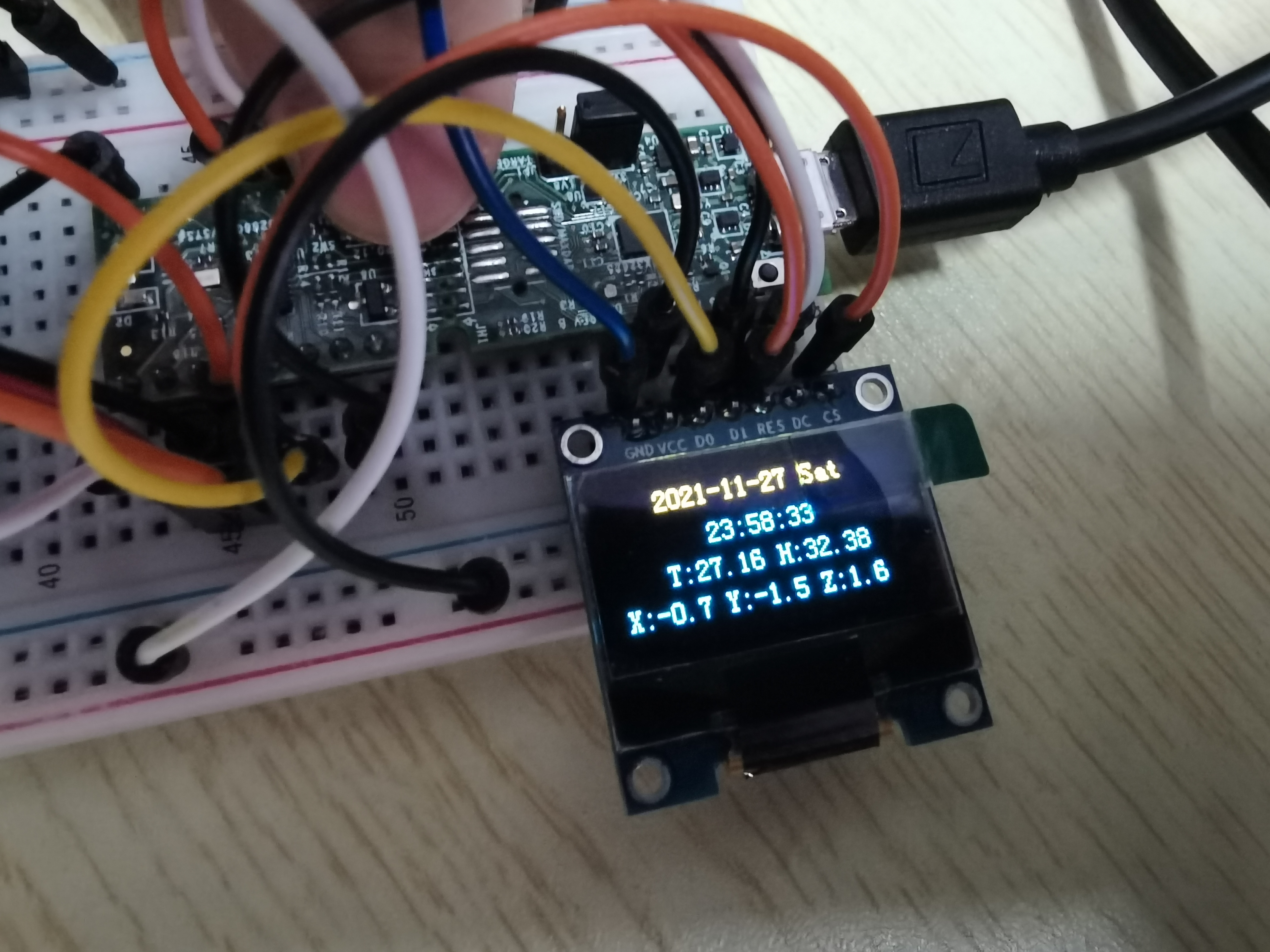
initialization
Set the initial time 2021-11-27 23:56:00, and the OLED displays as follows:
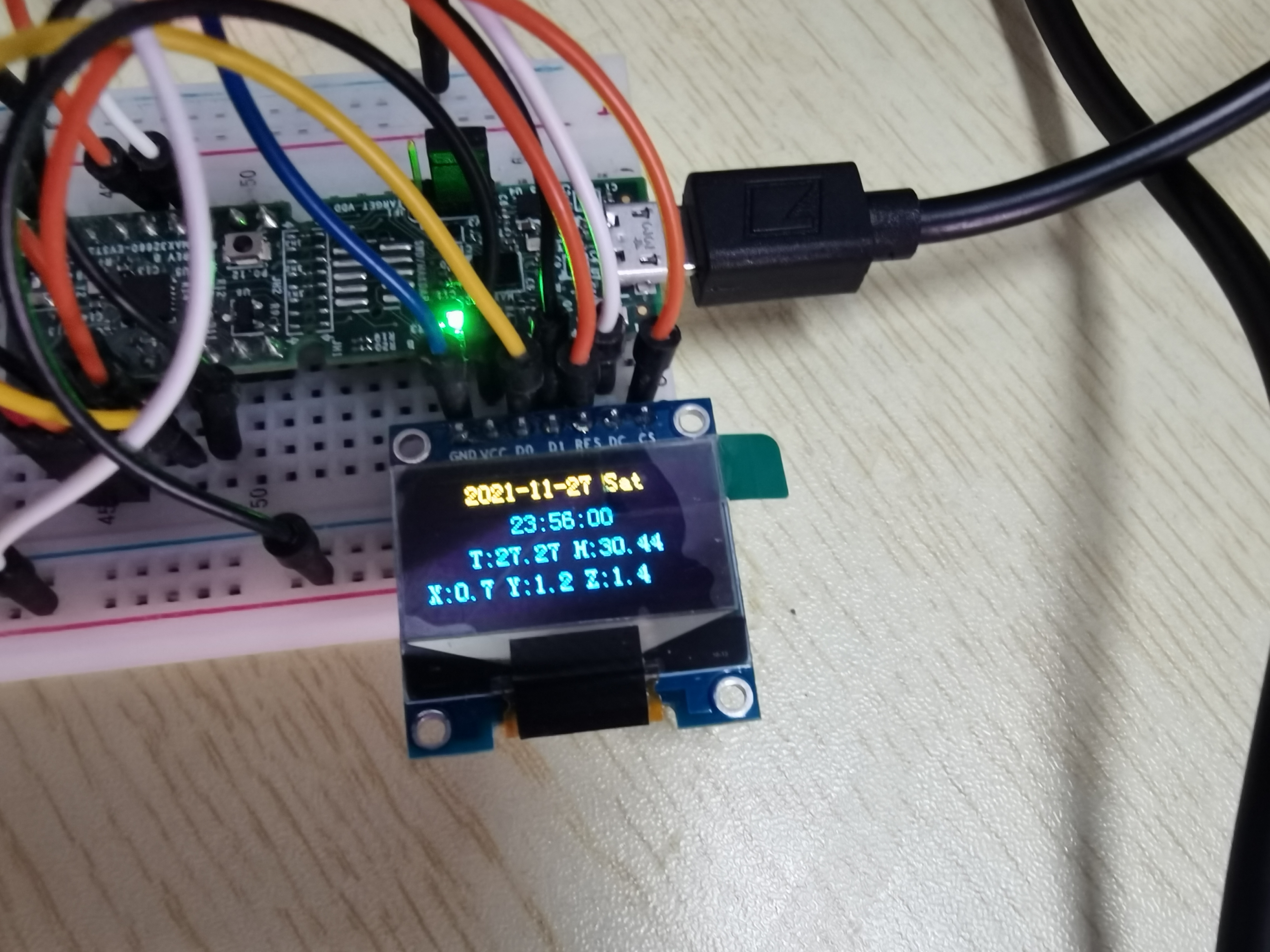
At this time, the temperature, humidity and inclination values have been read and displayed on the OLED screen.
Press the key to update immediately
Press the key, and the OLED changes as shown in the following two figures:
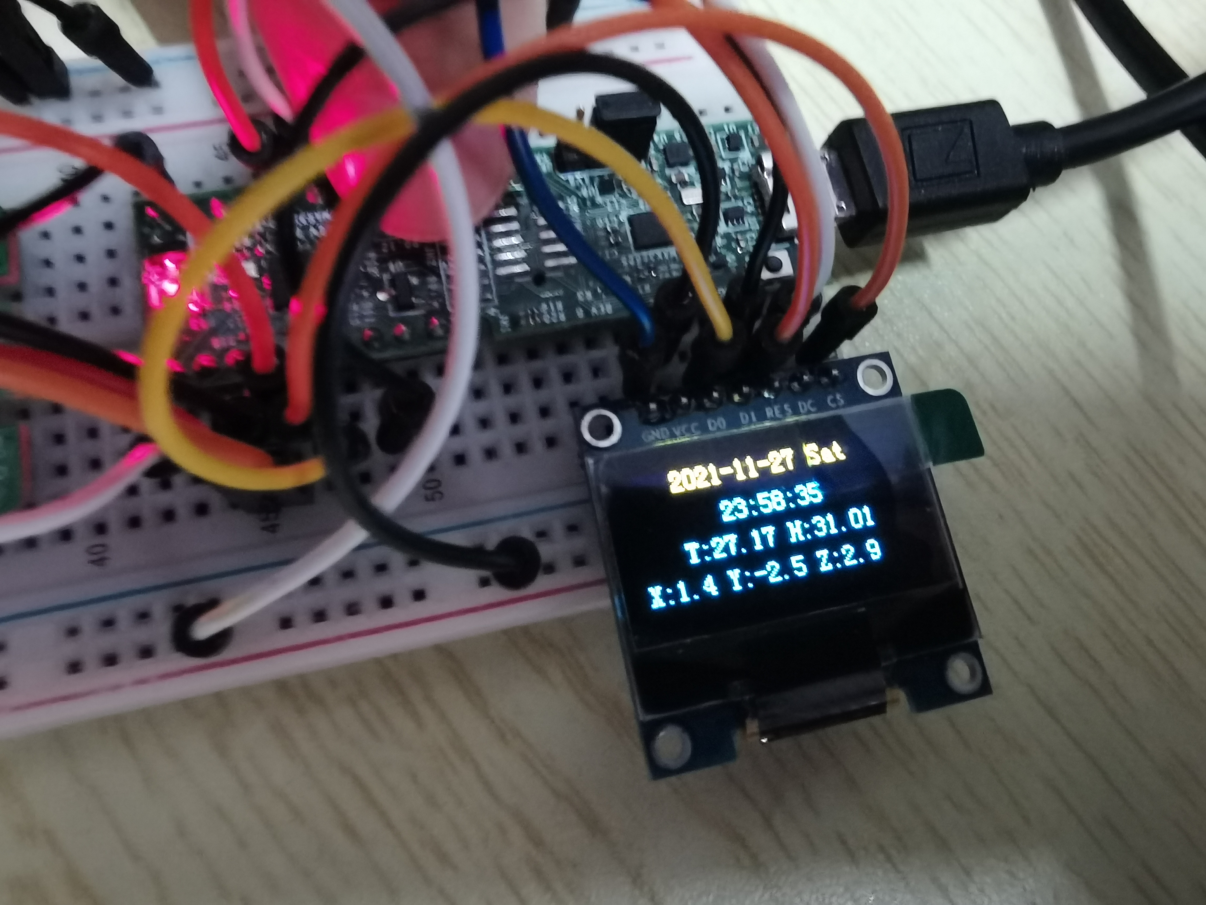
It can be found that when pressed, the LED light is on, and the temperature, humidity and inclination information change.
Automatic update every minute
Since the initial time is set to 00 seconds, the value is automatically updated every minute, as shown in the following two figures:
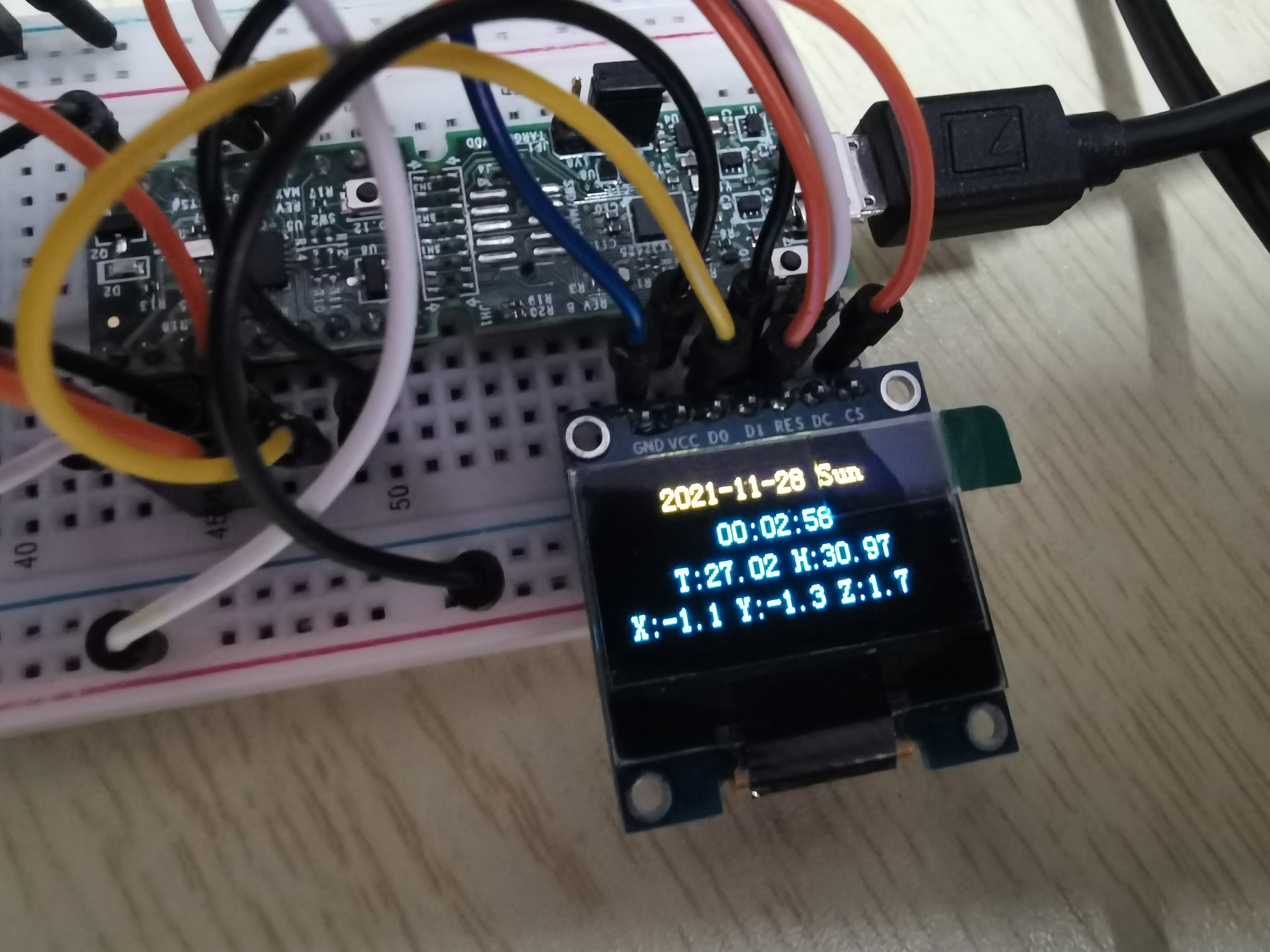
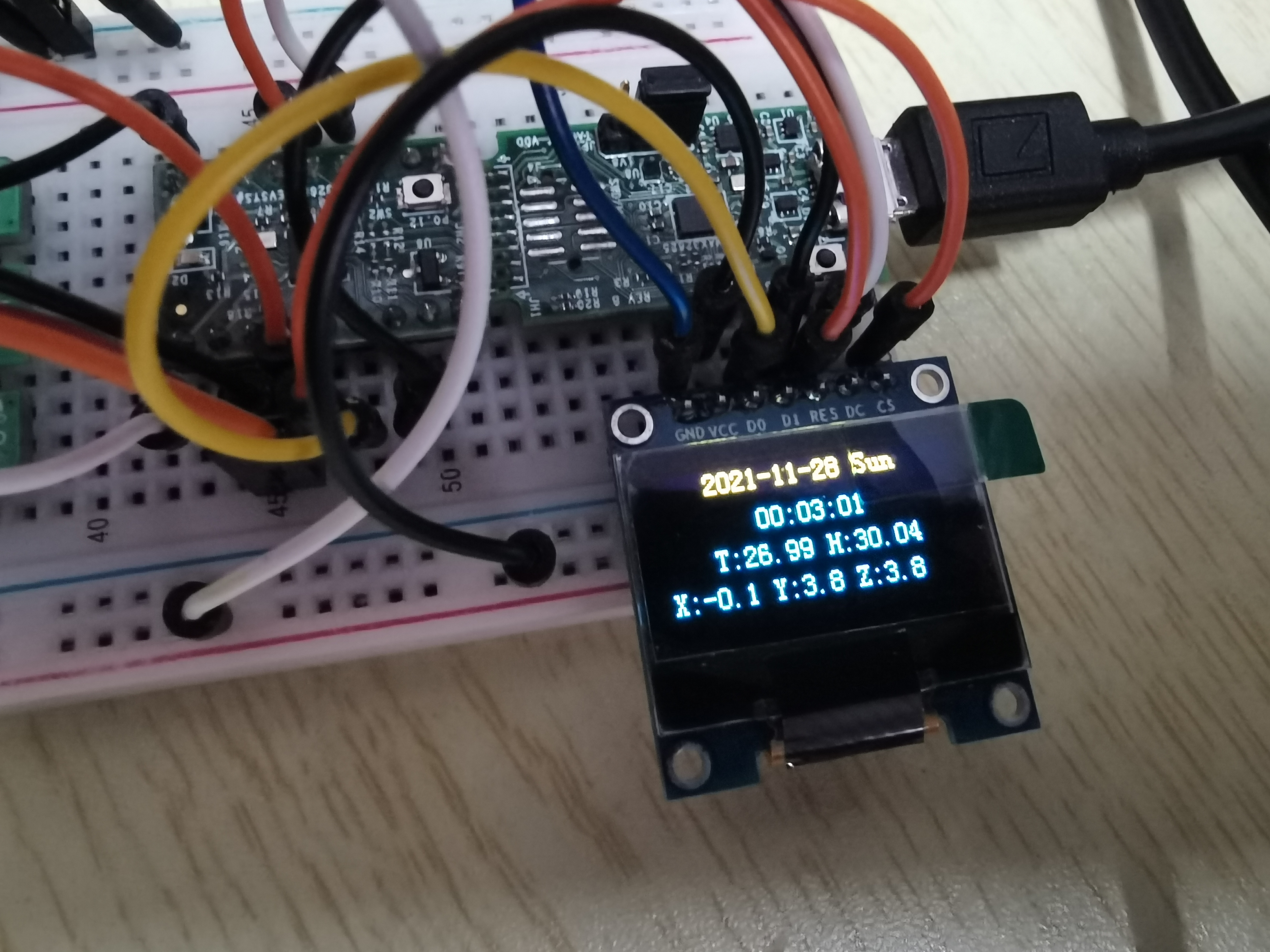
Due to the delay of the program and the time required for I2C reading and writing when reading data, OLED seconds will be displayed, but the RTC time is still accurate.
Project summary
- Although the MAX32660 sparrow used this time is small, it has all kinds of internal organs. Unfortunately, there are too few GPIO ports. Finally, I want to add a serial port to update the initial value of time, but there is no redundant UART to use;
- ADXL345 originally intended to use the interrupt to detect the free fall, but there may be a problem with the setting. The interrupt cannot come out, and only the inclination can be measured;
- Later, I hope to change the screen to I2C communication, so that one more serial port resource can be provided, and I hope to use RTC to realize some scenarios such as alarm clock, low power consumption and Automatic wake-up.
Source file resources: to be supplemented