Chapter 10 Redis high availability
Learning objectives
-
Understand Redis cache cluster scheme
-
Be able to use spring to integrate Redis cluster environment
The theme of this chapter is Redis. At present, Redis has been widely used in enterprises, and Redis is also the key content in the interview.
1. Redis cache related issues
[Objective]
1: Understand Redis cache penetration
2: Understand Redis cache avalanche
3: Understand Redis cache breakdown
[path]
1: Cache penetration description and solution
2: Cache avalanche description and solution
3: Cache breakdown description and solution
[explanation]
1.1. Cache penetration [ interview ]
**Cache penetration * * refers to querying data that must not exist in a database.
Our previous normal process of using Redis cache is roughly as follows:
The first query starts from jedis.get (setmealdetail {ID}). If it does not exist, query the database, obtain it and store it in redis (setmealdetail {ID})
If the package data does not exist, it does not need to be put into the cache
1. The data query starts with the cache query id=1setmealDetail_id = null
2. If the data exists, the cached data is returned directly
3. If the data does not exist, query the database and put the queried data into cache 1
4. If the database query data is empty, it will not be put into the cache
For example, the primary key in our data table is generated by self increment, and all primary key values are greater than 0. What happens if the parameter passed in by the user is - 1? This - 1 is an object that must not exist. The program will query the database every time, and every query is empty and will not be cached every time. If someone maliciously attacks, we can take advantage of this vulnerability, put pressure on the database, and even crush our database.
Solution: in order to prevent someone from using this vulnerability to maliciously attack our database, we can take the following measures:
If the object queried from the database is empty, it is also put into the cache. The key is the primary key value submitted by the user, and the value is null, but the set cache expiration time is short, such as 60 seconds. In this way, the next time the user queries the redis cache according to this key, the value can be queried (of course, the value is null), so as to protect our database from attack. It disappears when it expires. In order to return real data in the future
If the IDs are in order, the maximum value (with data) of the id can be stored when storing the null value. When querying, judge whether the range of the query id is greater than the maximum value and directly return null
1.2. Cache avalanche [interview]
Phenomenon description: cache avalanche means that the cache set expires in a certain period of time. During the time period when the cache set fails, all the data access queries fall on the database, which will produce periodic pressure peaks for the database.
Solution: in order to avoid cache avalanche, we can set different expiration times for cached data, so as to avoid the failure of cached data in a certain time period. For example, popular data (data with high access frequency) can be cached for a longer time, and unpopular data can be cached for a shorter time. Even for some particularly popular data, you can set never expire (memory overhead). There are other third-party caches (memory cache, cache in JVM: Spring Cache, Mybatis L2 cache)
Set different failure duration
Extension of validity
Add third party cache
1.3. Interview
Phenomenon description: cache breakdown means that a key is very hot (for example, the commodity data snapped up during the double 11 Festival). It is constantly carrying large concurrency, and the large concurrency focuses on accessing this point. When the key fails, the continuous large concurrency breaks through the cache and requests directly to the database, just like cutting a hole in a barrier.
Solution: we can also set these hot data to never expire to solve the problem of cache breakdown, or extend the expiration time periodically
[summary]
1: Cache penetration (query nonexistent data), and save null in the solution, set a shorter expiration time, and set the range of null values for sequential data
2: Cache Avalanche (a large number of caches fail at the same time), and the solution sets different failure times to prolong the effective time, supplemented by a third-party cache
3: Cache breakdown (high concurrency key failure instant), and solutions, extending the expiration time or even permanently effective. Regular or manual deletion
1.4 Redis performance test
1.4.1 objectives
- Master Redis performance test methods
1.4.2 route
- Redis installation
- Instructions for redis benchmark tool
- TPS, QPS, RT explanation
- Measure Redis performance
1.4.3 explanation
1.4.3.1 installing redis
To install a c + + environment in a virtual machine:
yum install gcc-c++
To install Redis, execute the following commands in sequence:
#Upload redis-4.0.14.tar.gz
put
# decompression
tar -zxf redis-4.0.14.tar.gz
# Enter the decompression directory
cd redis-4.0.14
# compile
make
# install
make install PREFIX=/usr/local/redis
# Enter the installed redis directory
cd /usr/local/redis/bin
# Copy profile
cp /root/redis-4.0.14/redis.conf ./

#Setting environment variables
vi /etc/profile
#Add at the end of the file
export REDIS_HOME=/usr/local/redis
export PATH=$PATH:$REDIS_HOME/bin
#Effective using environment variables
source /etc/profile

# Modify profile
vi redis.conf
# Redis background startup
 modify daemonize by yes
# Redis server can be accessed across networks
 modify bind Is 0.0.0.0
# Enable aof persistence
appendonly yes

# Start redis
redis-server redis.conf
1.4.3.2 redis-benchmark
Redis benchmark is the official redis performance test tool. It is used to test the read-write performance of redis in the current environment. When we use redis, the hardware configuration, network status and test environment of the server will affect the performance of redis. We need to test redis in real time to determine the actual performance of redis.
Use syntax:
redis-benchmark [parameter] [Parameter value]
Parameter Description:
| option | describe | Default value |
|---|---|---|
| -h | Specify the server host name | 127.0.0.1 |
| -p | Specify server port | 6379 |
| -s | Specify server socket | |
| -c | Specifies the number of concurrent connections | 50 |
| -n | Specify the number of requests | 10000 |
| -d | Specifies the data size of the SET/GET value in bytes | 3 |
| -k | 1=keep alive 0=reconnect | 1 |
| -r | SET/GET/INCR uses random keys and Sadd uses random values | |
| -P | Pipeline requests | 1 |
| -q | Force the exit of redis. Only the query/sec value is displayed | |
| –csv | Export in CSV format | |
| -l | Generate a loop and permanently execute the test | |
| -t | Run only a comma separated list of test commands. | |
| -I | Idle mode. Open only N idle connections and wait. |
Common: - c -n -d -t
Test the performance by executing the following command:
# Execute test performance command
./redis-benchmark -t set,get -n 100000
The results are as follows:
====== SET ======
  100000 requests completed in 1.97 seconds
  50 parallel clients
  3 bytes payload
  keep alive: 1

95.32% <= 1 milliseconds
99.46% <= 2 milliseconds
99.67% <= 3 milliseconds
99.72% <= 4 milliseconds
99.84% <= 5 milliseconds
99.88% <= 6 milliseconds
99.90% <= 10 milliseconds
99.95% <= 18 milliseconds
99.97% <= 19 milliseconds
100.00% <= 19 milliseconds
50761.42 requests per second

====== GET ======
  100000 requests completed in 1.92 seconds
  50 parallel clients
  3 bytes payload
  keep alive: 1

97.49% <= 1 milliseconds
99.95% <= 16 milliseconds
100.00% <= 16 milliseconds
52110.47 requests per second
In the above test results, we focus on the last line of the GET result, 52110.47 requests per second, that is, the GET command processes 52110.47 requests per second, that is, QPS 52000. However, the data here are only ideal test data, and the measured QPS cannot represent the processing capacity of the actual production.
1.4.3.3 TPS,QPS,RT
When describing the high concurrency capability of the system, throughput (TPS), QPS and response time (RT) are often mentioned. Let's understand these concepts first:
- Response time RT
- Throughput TPS
- Query rate per second QPS
**Response time (RT)**
Response time refers to the time when the system responds to requests.
Intuitively, this index is very consistent with people's subjective feelings about software performance, because it completely records the time of the whole computer system processing requests. Because a system usually provides many functions, and the business logic of different functions is also very different, the response time of different functions is also different.
When discussing the response time of a system, it usually refers to the average time of all functions of the system or the maximum response time of all functions.
Throughput TPS
Throughput refers to the number of requests processed by the system in unit time (s seconds). How many requests can be processed per second
For a multi-user system, if only one user uses it, the average response time of the system is t. when you have n users, the response time seen by each user is usually not n × t. And often more than n × T is much smaller. This is because when processing a single request, many resources may be idle at each time point. When processing multiple requests, if the resource configuration is reasonable, the average response time seen by each user does not increase linearly with the increase of the number of users.
In fact, the average response time of different systems increases at different rates with the increase of users, which is also the main reason why throughput is used to measure the performance of concurrent systems. Generally speaking, throughput is a general indicator. If the maximum throughput of two systems with different user numbers and user usage patterns is basically the same, it can be judged that the processing capacity of the two systems is basically the same.
1.The concurrency of the server is 100,Response time is 100 ms  1000ms/100ms every time = 10 Each handover can process 100 requests concurrently, so it can process 10 times a second*100 request=1000 Requests, therefore TPS 1000

2.TPS calculation(1s):
	1 Concurrent   	1000ms/100ms/second*1=10              1 When concurrent, 10 requests can be processed TPS:10
    10 1000 concurrent ms/100ms*10=100            10 When concurrent, 100 requests can be processed   TPS:100
    100 1000 concurrent/100*100=1000          100 When concurrent, 1000 requests can be processed  TPS:1000
    200 100 concurrent processes,100 Concurrent wait throughput<1000
                (1000/100) / (200/100) 5 1000 requests per request
  TPS,It is related to the number of concurrent transactions. If the number of concurrent transactions exceeds, the loss will be less than the theoretical value
Query rate per second QPS
Query rate per second QPS is a measure of how much traffic a specific query server handles within a specified time. In the Internet, query rate per second is often used to measure the performance of the server. Corresponding fetches/sec, that is, the number of response requests per second, that is, the maximum throughput capacity.
####1.4.3.4 measuring Redis performance
In actual production, we need to care about how many QPS redis can handle in the application scenario. We need to estimate the size of the produced message and use the benchmark tool to specify -d data block size to simulate:
./redis-benchmark -t get -n 100000 -c 100 -d 2048
Test results:
====== GET ======
  100000 requests completed in 2.33 seconds
  100 parallel clients
  2048 bytes payload
  keep alive: 1

0.00% <= 1 milliseconds
51.74% <= 2 milliseconds
99.16% <= 3 milliseconds
99.57% <= 4 milliseconds
99.71% <= 5 milliseconds
99.83% <= 7 milliseconds
99.83% <= 8 milliseconds
99.86% <= 15 milliseconds
99.86% <= 16 milliseconds
99.90% <= 20 milliseconds
99.93% <= 21 milliseconds
99.94% <= 26 milliseconds
99.96% <= 29 milliseconds
99.97% <= 36 milliseconds
99.99% <= 37 milliseconds
100.00% <= 37 milliseconds
42955.32 requests per second
The measured QPS is 42000
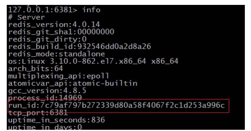
We can also use the redis client to log in to the redis service and execute the info command to view other redis information. Execute the command:
# Using Redis client
./redis-cli
# Execute the info command in the client
127.0.0.1:6379> info
View results (extract some results):
connected_clients:101 #Number of redis connections

used_memory:8367424	# Total memory allocated by Redis
used_memory_human:7.98M
used_memory_rss:11595776 # Total amount of Redis allocated memory (including memory fragments)
used_memory_rss_human:11.06M
used_memory_peak:8367424
used_memory_peak_human:7.98M #Peak value of memory used by Redis
used_memory_peak_perc:100.48%
1.4.4 summary
RT - average response time, or maximum response time per request
TPS throughput is related to the number of concurrencies that can be supported, the response speed, and the real amount of concurrency (non-linear)
QPS - query speed per second to measure network performance
To measure the performance of the server, the concurrency and data size should be taken during the test
2.Redis cluster scheme
The stand-alone redis can read and write very fast and can support the access of a large number of users. Although the performance of redis is very high, for large websites, the data to be obtained per second is far more than the pressure that a single redis service can bear. Therefore, we urgently need a solution to solve the problem of insufficient performance of a single redis service. This requires the use of redis clusters. There are many schemes for redis cluster, which are explained below.
2.1. Master-slave replication (read-write separation) [key]
2.1.1 objectives
- Master the construction of Redis read-write separation
2.1.2 route
- Introduction to Redis master-slave replication
- Redis master-slave replication implementation
- Redis synchronization principle
2.1.3 explanation
2.1.3.1 introduction to redis master-slave replication
We have tested it before. If there is only one server, the QPS is 42000. In large websites, higher QPS may be required. Obviously, one server can not meet the needs.
Redis On the scale of knowledge:
The total amount of machine memory is about 70 TB,The actual memory used is about 40 TB.
It processes about 15 million requests per second on average and about 20 million requests per second on peak. #QPS 20 million
 More than 1 trillion requests are processed every day.
A single cluster can process up to about 4 million requests per second.
We can extend the read-write capability and solve the performance bottleneck by separating read from write. Run a new service (called the slave server), connect the slave server with the master service, and then the master service sends the data copy. The slave server updates the data copy of the master server in quasi real time through the network (the specific update speed depends on the network bandwidth).
In this way, we have additional read requests from the server. By distributing the read requests to different services for processing, users can obtain additional read query processing ability from the newly added slave service.
Redis has found that this read-write separation scenario is particularly common. It integrates read-write separation for users. We only need to add a clause to the redis configuration file to configure the slave of host port statement
In the master-slave replication mode, Redis nodes have two roles: Master (also known as master) and slave (also known as slave). This mode cluster is composed of one master node and multiple slave nodes.
Principle: the master will synchronize the data to the slave, but the slave will not synchronize the data to the master. When slave starts, it will connect to the master to synchronize data.
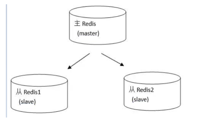
This is a typical distributed read-write separation model. We can use the master to handle write operations, and the slave provides read operations. This can effectively reduce the number of concurrent accesses of a single machine.
To implement master-slave replication, this mode is very simple. The master node can directly start the service without any modification. The slave node needs to modify the redis.conf configuration file and add the configuration: slaveof < master node ip address > < master node port number >. For example, the master's ip address is 192.168.200.129 and the port number is 6379, so the slave only needs to configure slaveof 192.168.200.129 6379 in the redis.conf file.
Connect the master node and the slave node respectively. The test finds that the master node writes, and the slave node can immediately see the same data. However, when writing to the slave node, you will be prompted that READONLY You can't write against a read only slave cannot write data to the slave node.
Now we can configure multiple slave nodes to read and master nodes to write in this way to realize the separation of reading and writing.
2.1.3.2 implementation of master-slave replication
Here, we put the master-slave replication implemented by three redis in one virtual machine. In the real production line environment, each redis should run independently on the ip of one computer
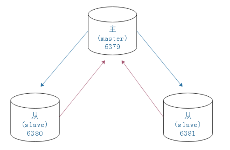
The master-slave replication structure we will build is as follows
# Copy redis
cd /usr/local
cp redis redis01 -R
cd redis01/bin
# Modify configuration
vi redis.conf
 modify port 6380
 The one from redis Finally add slaveof 192.168.175.128[For your virtual machine ip] 6379
# Empty persistent file
rm -rf dump.rdb
rm -rf appendonly.aof
# start-up
./redis-server redis.conf
# Start client

./redis-cli -p 6380
The steps are the same as above, and the server of 6381 is configured
6379
192.168.175.129:6379> info

Replication

role:master
connected_slaves:2
slave0:ip=192.168.175.129,port=6380,state=online,offset=588,lag=0
slave1:ip=192.168.175.129,port=6381,state=online,offset=588,lag=0
6380
192.168.175.129:6380> info

Replication

role:slave
master_host:192.168.175.129
master_port:6379
6381
192.168.175.129:6381> info

Replication

role:slave
master_host:192.168.175.129
master_port:6379
Test:
Master node
set name itcast: can be executed
get name: can execute
Slave node
set name itcast: err wrong number of arguments for 'get' command
get name: can execute
2.1.3.3 Redis synchronization principle [interview]
Through the above example, we know that the master-slave replication of redis, the master server executes the write command, and the slave server will synchronize the data to the slave server through the data change of the master server. However, if the master server goes offline and the slave server cannot connect to the master server, how can data synchronization get the command that the master server cannot be connected?
In master-slave replication, the databases of both the master and slave services will store the same data. Conceptually, this phenomenon is called consistent database state.
There are two methods for Redis database persistence: RDB full persistence and AOF incremental persistence.
Data synchronization steps:
-
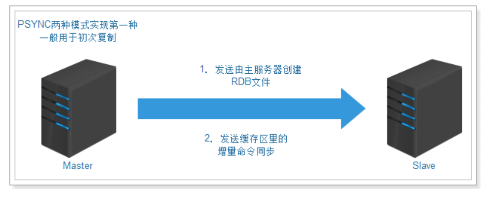
Before redis 2.8, the old version replication function SYNC was used, which is a very resource consuming operation
- The main server needs to execute BGSAVE command to generate RDB files, which will consume a lot of CPU, memory and disk read-write resources of the main server. A single key can store a maximum value of 512M
- The master server sends RDB files to the slave server. This sending operation will consume a lot of network bandwidth and flow of the master and slave server, and respond to commands to the master server
- The time of the request has an impact: the slave service that receives the RDB file is blocked in the process of loading the file and cannot process the command request
-
After 2.8, PSYNC is used, which has two modes: full resynchronization and partial resynchronization.
First full resynchronization:
Second partial resynchronization:
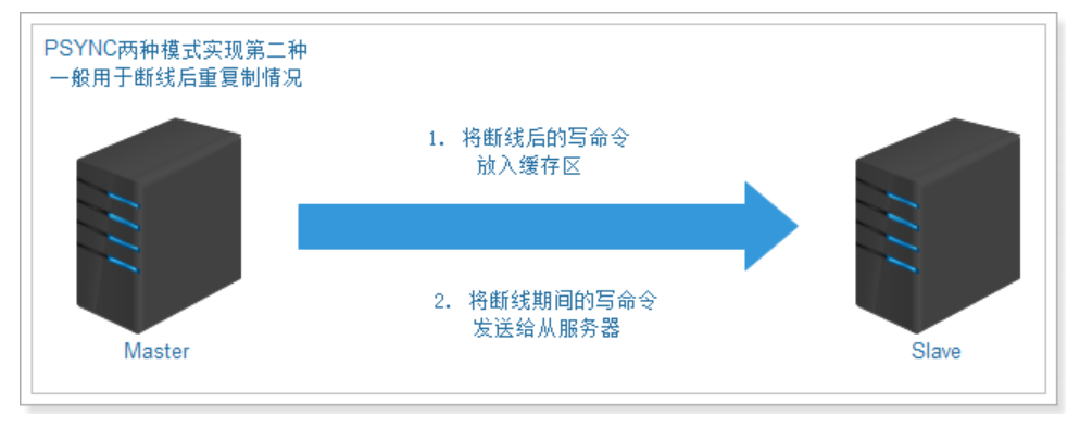
The function consists of the following three parts:
1) the replication offset of the master service and the replication offset of the slave server.
2) replication backlog of the main service. The default size is 1M.
3) the operation ID of the server, which is used to store the server ID:
If you disconnect and reconnect from the server, obtain the operation ID of the main server and compare it with the operation ID of the main server after reconnection,
Judge whether it is the original master server, so as to decide whether to perform partial resynchronization or complete resynchronization.
2.1.4 summary
-
Just follow the steps to build, or use rw script
-
There are two ways to synchronize redis data:
- The total amount of RDB. It occurs when the primary service is switched to another service. The primary service and the secondary service are never available (blocked)
- AOF increment: the master service receives the write operation and sends the write command to the slave service after processing
-
Manual master-slave switching
Turn the main shutdown
Execute a slave of no one from
The other slave executes slaveof new master ip
2.2. sentinel [key]
We have now implemented master-slave replication for Redis, which can synchronize the data of the master node to the slave node, realize the separation of reading and writing, and improve the performance of Redis. However, there is still a problem, that is, in the master-slave replication mode, there is only one master node. Once the master node goes down, it can no longer write. In other words, master-slave replication does not achieve high availability. So what is high availability? How to achieve high availability?
2.2.1. High availability introduction
High availability (HA) is one of the factors that must be considered in the architecture design of distributed system. It reduces the time when the system can not provide services through architecture design. To ensure high availability, the following points are usually followed:
- Single point is the enemy of high availability of the system, so we should try to avoid single point in the process of system design.
- The core criterion of ensuring high availability of the system through architecture design is redundancy.
- Automatic failover.
2.2.2. Introduction to redis Sentinel
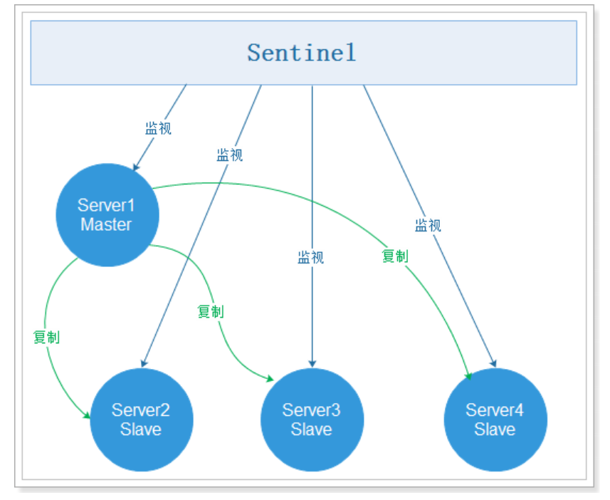
sentinel is a tool used to monitor the status of the Master in the Redis cluster. It is also an independent process. It is a highly available solution for Redis. sentinel mode has been integrated in the version after Redis 2.4.
sentinel can monitor one or more redis master services and all slave services of these master services; When a master service goes offline, it will automatically upgrade a service under the master to a master service instead of the offline master service to continue processing requests, and the remaining slave nodes will copy data from the new master node.
After redis installation, there will be a redis sentinel file, which is the script file for starting sentinel, and a sentinel.conf file, which is the sentinel configuration file.
sentinel working mode:
Note: there may be some questions. Now we have implemented high availability based on sentinel, but what if sentinel hangs? In fact, sentinel itself can also implement clustering, which means sentinel is also highly available. Multiple sentinels can monitor multiple redis master services and all slave services of these master services
2.2.3. Use of redis Sentinel
- Re prepare a cluster of master-slave replication 6379 master, 6380 slave, 6380 slave
- Configure sentinel
- Start sentinel
2.2.3.1. Configure sentinel
Sentinel is in the redis installation package. We can use it directly, but first we need to modify the configuration file and execute the command:
cd /usr/local/redis/

# Copy sentinel profile
cp /usr/local/redis/sentinel.conf sentinel01.conf

# To modify a profile:
vi sentinel01.conf
Add in the sentinel01.conf configuration file:
# Externally accessible
bind 0.0.0.0
sentinel monitor mymaster 127.0.0.1 6379 1
sentinel down-after-milliseconds mymaster 10000
sentinel failover-timeout mymaster 60000
sentinel parallel-syncs mymaster 1
Note: if sentinel monitor mymaster 127.0.0.1 6379 2 is configured, it will be commented out because we now have only one Sentinel node.
sentinel monitor mymaster 127.0.0.1 6379 1
sentinel down-after-milliseconds mymaster 10000
sentinel failover-timeout mymaster 60000
sentinel parallel-syncs mymaster 1
If the above four configurations are set to new values, it is best to comment out all the previous values, otherwise there may be problems.
Parameter Description:
-
sentinel monitor mymaster 192.168.200.129 6379 1
The name of the main node of mymaster can be named arbitrarily, but it must be consistent with the following configuration.
192.168.200.128 6379 master node connection address.
1. Voting is required to judge the primary server as invalid. At least one Sentinel consent is required for setting here.
-
sentinel down-after-milliseconds mymaster 10000
Sets the number of milliseconds required for Sentinel to believe that the service has been disconnected.
-
sentinel failover-timeout mymaster 60000
Set the expiration time for failover. After the failover starts, no failover operation is triggered within this time. Currently sentinel will consider the failover failed.
-
sentinel parallel-syncs mymaster 1
Set the maximum number of slave servers that can synchronize the new master service at the same time when performing failover. The smaller the number, the fewer slave servers that synchronize at the same time, and the longer it takes to complete failover.
2.2.3.2. Start sentinel
After modifying the configuration file, execute the following command to start sentinel:
[root@itheima redis]# ./bin/redis-sentinel ./sentinel01.conf
perhaps
[root@itheima redis]# /user/local/redis/bin/redis-sentinel sentinel01.conf
The effects are as follows:
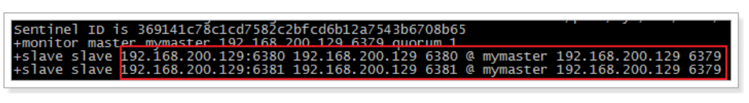
As you can see, 6379 is the master service and 6380 and 6381 are slave services.
2.2.3.3. Test sentinel
We execute shutdown at 6379 and close the main service. Sentinel prompts as follows:
+sdown master mymaster 192.168.200.129 6379	#Primary node downtime
+odown master mymaster 192.168.200.129 6379 #quorum 1/1
+new-epoch 1
+try-failover master mymaster 192.168.200.129 6379 #Attempt failover
+vote-for-leader 00a6933e0cfa2b1bf0c3aab0d6b7a1a6455832ec 1 #Elected leaders
+elected-leader master mymaster 192.168.200.129 6379
+failover-state-select-slave master mymaster 192.168.200.129 6379 #Failover select slave service
+selected-slave slave 192.168.200.129:6380 192.168.200.129 6380 @ mymaster 192.168.200.129 6379
#The failover status is sent to 6380
+failover-state-send-slaveof-noone slave 192.168.200.129:6380 192.168.200.129 6380 @ mymaster 192.168.200.129 6379
+failover-state-wait-promotion slave 192.168.200.129:6380 192.168.200.129 6380 @ mymaster 192.168.200.129 6379
+promoted-slave slave 192.168.200.129:6380 192.168.200.129 6380 @ mymaster 192.168.200.129 6379
+failover-state-reconf-slaves master mymaster 192.168.200.129 6379
+slave-reconf-sent slave 192.168.200.129:6381 192.168.200.129 6381 @ mymaster 192.168.200.129 6379
+slave-reconf-inprog slave 192.168.200.129:6381 192.168.200.129 6381 @ mymaster 192.168.200.129 6379
+slave-reconf-done slave 192.168.200.129:6381 192.168.200.129 6381 @ mymaster 192.168.200.129 6379
+failover-end master mymaster 192.168.200.129 6379 #After failover, the original main service is 6379
+switch-master mymaster 192.168.200.129 6379 192.168.200.129 6380 #Change the main service from the original 6379 to the current 6380
+slave slave 192.168.200.129:6381 192.168.200.129 6381 @ mymaster 192.168.200.129 6380
+slave slave 192.168.200.129:6379 192.168.200.129 6379 @ mymaster 192.168.200.129 6380
+sdown slave 192.168.200.129:6379 192.168.200.129 6379 @ mymaster 192.168.200.129 6380
According to the prompt information, we can see that 6379 failed over to 6380 and voted to select 6380 as the new primary server.
Execute info at 6380
# Replication
role:master
connected_slaves:1
slave0:ip=127.0.0.1,port=6381,state=online,offset=80531,lag=1
Execute info at 6381
# Replication
role:slave
master_host:127.0.0.1
master_port:6380
master_link_status:up
The failover is shown in the figure below:
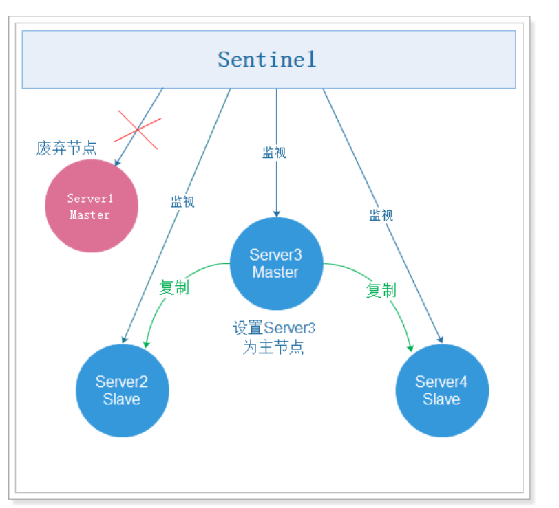
At this time: 6380 is the primary node and can write.
However, if 6379 is restarted, 6380 is still the master node and 6379 is the slave node.
####2.2.3.4. Principle [interview]
Sentinel mainly monitors the status of the server and decides whether to fail over. How to perform failover has been demonstrated in the previous section. How does sentinel judge whether the service is offline? It is mainly divided into subjective offline and objective offline:
-
Subjective offline:
-
Concept:
Subjective down (SDOWN) refers to the offline judgment made by a single Sentinel instance on the service
-
characteristic:
If a service does not return a valid reply to the Sentinel sending the PING command within the time specified by the master down after milliseconds option, the Sentinel will mark the server as offline
-
-
Objective offline
-
Concept:
After multiple Sentinel examples make SDOWN judgment on the same service and communicate with each other through the Sentinel is master down by addr command, the obtained service is offline to judge ODOWN. (a Sentinel can send a command to another Sentinel to ask if the other Sentinel thinks that a given server is offline)
-
characteristic:
Switching from subjective offline status to objective offline status does not use a strict quorum algorithm, but uses Gossip: if sentinel receives a sufficient number of primary service offline reports from other sentinels within a given time range, Sentinel will change the status of the primary server from subjective offline to objective offline.
-
Note:
The objective offline conditions are only applicable to the main service. For other types of Redis instances, Sentinel does not need to negotiate before judging them as offline, so the slave server or other Sentinel will not meet the objective offline conditions. As long as a Sentinel finds that a primary server has entered the objective offline state, the Sentinel may be selected by other sentinels and perform automatic fault migration for the failed primary service.
-
####2.2.3.5 summary
Sentinel's three major tasks
-
Monitoring: Sentinel will constantly check whether your master server and slave server are working normally.
-
Notification: when a monitored Redis server has a problem, Sentinel can send a notification to the administrator or other applications through the API.
-
Automatic failover: when a primary service fails to work normally, Sentinel will start an automatic failover operation. It will upgrade one of the failed primary services from the service to the new primary service, and change the others of the failed primary services from the service to the new primary server== The election basis = = is as follows: normal network connection - > reply to INFO command within 5 seconds - > 10 * down after milliseconds - > slave server priority - > copy offset - > those with small operation id. After selection, upgrade the slave server to a new master server through slave if no one
When the client attempts to connect to the failed primary server, the cluster will also return the address of the new primary server to the client, so that the cluster can use the new primary service instead of the failed service.
-
Slave server priority: the slave priority configuration item in redis.conf. the smaller the value, the higher the priority
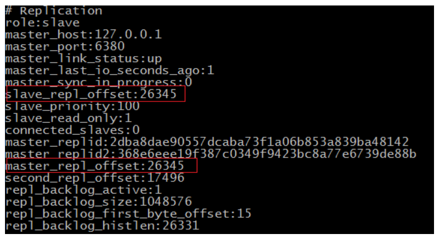
-
Copy offset: master_repl_offset is the copy offset of the master node. The offset in slave x is the copy offset of the slave node. The difference between the two is the delay of the master and slave
-
- Runtime id
3.3.4 Internet cold standby and hot standby
-
Cold standby
-
Concept:
Cold standby occurs when the database has been shut down normally. When it is shut down normally, it will provide us with a complete database
-
advantage:
- Very fast backup method (just copy files)
- Low maintenance and high safety
-
Disadvantages:
- When used alone, it can only provide recovery "at a certain point in time"
- In the whole process of backup, the database must be backed up instead of other work. In other words, during cold backup, the database must be closed
-
-
Hot standby
-
Concept:
Hot backup is a method of backing up the database in archive mode when the database is running
-
advantage:
- Short backup time
- The database is still available during backup
- Second recovery
-
Disadvantages:
- If the hot backup is not successful, the results can not be used for point in time recovery
- It is difficult to maintain, so be very careful
-
2.3. Redis built-in cluster
2.3.1. Introduction to redis cluster
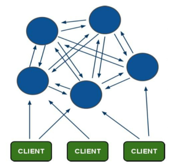
Redis Cluster is the built-in cluster of redis. It is an implementation scheme launched in Redis3.0. Before redis 3.0, there was no built-in cluster. Redis Cluster is a cluster architecture without a central node. It relies on the mission protocol to automatically repair the state of the cluster.
In the design of Redis cluster, decentralization and middleware are taken into account, that is, each node in the cluster is equal and equal, and each node saves its own data and the state of the whole cluster. Each node is connected to all other nodes, and these connections remain active, which ensures that we only need to connect to any node in the cluster to obtain the data of other nodes.
The Redis cluster architecture is as follows:
2.3.2. Hash slot allocation data [interview]
It should be noted that in this cluster mode, the data saved by each node in the cluster is not all data, but only part of data. So how is the data reasonably allocated to different nodes?
Redis cluster uses a method called hash slot to allocate data. The redis cluster assigns 16384 slots by default. When we set a key, we will use the CRC16 algorithm to obtain the slot, and then assign the key to the node in the hash slot interval. The specific algorithm is CRC16 (key)% 16384.
Suppose that three nodes have formed a cluster: A, B and C. they can be three ports on one machine or three different servers. Then, if 16384 slots are allocated by hash slots, the slot intervals undertaken by their three nodes are:
- Node A covers 0-5460
- Node B covers 5461-10922
- Node C covers 10923-16383
Now, set a key, such as my_name:
set my_name itcast
According to the hash slot algorithm of redis cluster: CRC16('my_name')%16384 = 2412. Then the storage of this key will be allocated to node A.
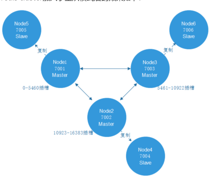
2.3.3. Master slave mode of redis cluster
In order to ensure the high availability of data, the redis cluster adds the master-slave mode. A master node corresponds to one or more slave nodes. The master node provides data access, and the slave node pulls data backups from the master node. When the master node hangs up, one of these slave nodes will be selected as the master node to ensure that the cluster will not hang up.
The effects of adding master-slave mode to redis cluster are as follows:
2.3.4. Redis cluster setup
2.3.4.1. Preparing Redis node
In order to ensure that elections can be held, at least three master nodes are required.
Each master node requires at least one slave node, so at least three slave nodes are required.
A total of 6 redis servers are required. We use 6 redis instances with port numbers of 7001 ~ 7006.
First prepare a clean redis environment, copy the original bin folder, and then clean it as the first redis node. The specific commands are as follows:
# Enter the redis installation directory
cd /usr/local
# Copy redis
mkdir cluster
cp -R ./redis ./cluster/node1
# Delete persistent file
cd cluster/node1/bin
rm -rf dump.rdb
rm -rf appendonly.aof
# Delete the original profile
rm -rf redis.conf
# Copy new profile
cp /root/redis-4.0.14/redis.conf ./
# Modify profile
vi redis.conf
The configuration file of the redis node in the cluster environment is as follows: put it at the end of the file.
# The password cannot be set, otherwise the cluster will not be connected when it is started
# Redis server can be accessed across networks
bind 0.0.0.0
# Modify the port number (six machines are configured with 700170027003700470057006 respectively)
port 7001
# Redis background startup
daemonize yes
# Enable aof persistence
appendonly yes
# Start cluster
cluster-enabled yes
# The configuration file of the cluster starts automatic generation for the first time (it can not be configured)
cluster-config-file nodes_7001.conf
# Request timeout (can not be configured)
cluster-node-timeout 5000
Back to the cluster directory, after the first redis node node1 is ready, copy five copies respectively,
cp -R node1/ node2
cp -R node1/ node3
cp -R node1/ node4
cp -R node1/ node5
cp -R node1/ node6
Modify the port numbers of the six nodes to 7001 ~ 7006, and modify the bin/redis.conf configuration file
vi node2/bin/redis-conf
vi node3/bin/redis-conf
vi node4/bin/redis-conf
vi node5/bin/redis-conf
vi node6/bin/redis-conf
Script the startup node:
vi start-all.sh
The content is:
cd node1/bin
./redis-server redis-conf
cd ..
cd ..
cd node2/bin
./redis-server redis-conf
cd ..
cd ..
cd node3/bin
./redis-server redis-conf
cd ..
cd ..
cd node4/bin
./redis-server redis-conf
cd ..
cd ..
cd node5/bin
./redis-server redis-conf
cd ..
cd ..
cd node6/bin
./redis-server redis-conf
cd ..
cd ..
[root@itheima cluster]# ll
 Total consumption 28
drwxr-xr-x. 2 root root 4096 12 September 22:00 node1
drwxr-xr-x. 2 root root 4096 12 September 22:02 node2
drwxr-xr-x. 2 root root 4096 12 September 22:03 node3
drwxr-xr-x. 2 root root 4096 12 September 22:03 node4
drwxr-xr-x. 2 root root 4096 12 September 22:03 node5
drwxr-xr-x. 2 root root 4096 12 September 22:04 node6
-rw-r--r--. 1 root root  246 12 September 22:07 start-all.sh
However, looking at the start-all.sh file, it is found that - rw-r – R -- indicates that you do not have permission and you need to set permission
Set the permissions for the script and start:
chmod 744 start-all.sh
./start-all.sh
Use the command ps -ef | grep redis to view the effect as follows:
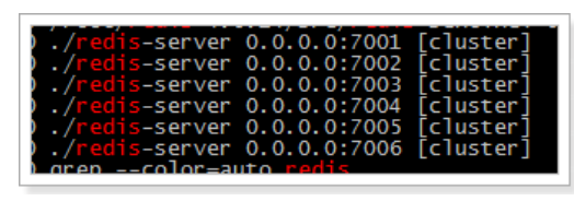
The above six nodes are not clusters. How to set the six nodes as clusters?
2.3.4.2. Start Redis cluster
The management tool of redis cluster uses Ruby script language. Installing the cluster requires a ruby environment. First install the ruby environment:
# Install ruby
yum -y install ruby ruby-devel rubygems rpm-build

# Upgrade ruby Version. redis4.0.14 cluster environment requires ruby Version above 2.2.2
yum install centos-release-scl-rh
yum install rh-ruby23  -y
scl enable rh-ruby23 bash

# View ruby Version
ruby -v
Download gem meeting environmental requirements at the following address:
https://rubygems.org/gems/redis/versions/4.1.0
redis-4.1.0.gem has been provided in the course materials. You can upload and install it directly. The installation command is:
# Upload redis-4.1.0.gem using sftp
[root@itheima ~]# ll
 Total dosage 185996
-rw-------. 1 root root      1438 5 June 14, 2019 anaconda-ks.cfg
-rw-r--r--. 1 root root     27338 5 June 14, 2019 install.log
-rw-r--r--. 1 root root      7572 5 June 14, 2019 install.log.syslog
-rw-r--r--. 1 root root 188607817 7 August 28, 2018 jdk-8u181-linux-i586.tar.gz
drwxrwxr-x. 6 root root      4096 3 June 19, 2019 redis-4.0.14
-rw-r--r--. 1 root root   1740967 11 December 15:44 redis-4.0.14.tar.gz
-rw-r--r--. 1 root root     55808 11 December 15:44 redis-4.1.0.gem
# install
gem install redis-4.1.0.gem
Enter the redis installation directory, use the cluster management script provided by redis, and execute the command:
# Enter redis installation package
cd /root/redis/src/
# Viewing cluster management scripts
ll *.rb
# Use the cluster management script to start the cluster. 1 in the following command means to create 1 slave node for each master node (you can open it in the text, edit it, and then copy it)
./redis-trib.rb create --replicas 1 192.168.175.128:7001 192.168.175.128:7002 192.168.175.128:7003 192.168.175.128:7004 192.168.175.128:7005 192.168.175.128:7006
The effects are as follows:
>>> Creating cluster
>>> Performing hash slots allocation on 6 nodes...
Using 3 masters:
192.168.200.129:7001
192.168.200.129:7002
192.168.200.129:7003
Adding replica 192.168.200.129:7005 to 192.168.200.129:7001
Adding replica 192.168.200.129:7006 to 192.168.200.129:7002
Adding replica 192.168.200.129:7004 to 192.168.200.129:7003
>>> Trying to optimize slaves allocation for anti-affinity
[WARNING] Some slaves are in the same host as their master
M: f0094f14b59c023acd38098336e2adcd3d434497 192.168.200.129:7001
   slots:0-5460 (5461 slots) master
M: 0eba44418d7e88f4d819f89f90da2e6e0be9c680 192.168.200.129:7002
   slots:5461-10922 (5462 slots) master
M: ac16c5545d9b099348085ad8b3253145912ee985 192.168.200.129:7003
   slots:10923-16383 (5461 slots) master
S: edc7a799e1cfd75e4d80767958930d86516ffc9b 192.168.200.129:7004
   replicates ac16c5545d9b099348085ad8b3253145912ee985
S: cbd415973b3e85d6f3ad967441f6bcb5b7da506a 192.168.200.129:7005
   replicates f0094f14b59c023acd38098336e2adcd3d434497
S: 40fdde45b16e1ac85c8a4c84db75b43978d1e4d2 192.168.200.129:7006
   replicates 0eba44418d7e88f4d819f89f90da2e6e0be9c680
Can I set the above configuration? (type 'yes' to accept): yes #Note: select yes
>>> Nodes configuration updated
>>> Assign a different config epoch to each node
>>> Sending CLUSTER MEET messages to join the cluster
Waiting for the cluster to join..
>>> Performing Cluster Check (using node 192.168.200.129:7001)
M: f0094f14b59c023acd38098336e2adcd3d434497 192.168.200.129:7001
   slots:0-5460 (5461 slots) master
   1 additional replica(s)
M: ac16c5545d9b099348085ad8b3253145912ee985 192.168.200.129:7003
   slots:10923-16383 (5461 slots) master
   1 additional replica(s)
S: cbd415973b3e85d6f3ad967441f6bcb5b7da506a 192.168.200.129:7005
   slots: (0 slots) slave
   replicates f0094f14b59c023acd38098336e2adcd3d434497
S: 40fdde45b16e1ac85c8a4c84db75b43978d1e4d2 192.168.200.129:7006
   slots: (0 slots) slave
   replicates 0eba44418d7e88f4d819f89f90da2e6e0be9c680
M: 0eba44418d7e88f4d819f89f90da2e6e0be9c680 192.168.200.129:7002
   slots:5461-10922 (5462 slots) master
   1 additional replica(s)
S: edc7a799e1cfd75e4d80767958930d86516ffc9b 192.168.200.129:7004
   slots: (0 slots) slave
   replicates ac16c5545d9b099348085ad8b3253145912ee985
[OK] All nodes agree about slots configuration.
>>> Check for open slots...
>>> Check slots coverage...
[OK] All 16384 slots covered.
2.3.5. Using Redis cluster
According to the characteristics of redis cluster, it is decentralized, and each node is peer-to-peer, so the connected node can obtain and set data.
Query cluster information:
redis-cli -p 7001 cluster nodes
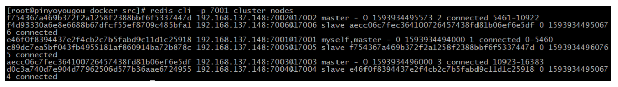
Use the redis client to connect to the redis cluster. The command is as follows:
# Enter the bin directory
cd /usr/local/cluster/node1/bin
# Start the client program
./redis-cli -h 192.168.175.128 -p 7001 -c
Among them, - c must be added. This is the parameter for node jump during redis cluster connection.
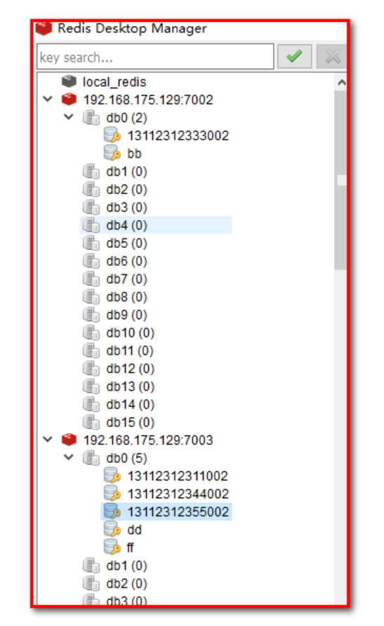
After connecting to the cluster, you can set some values. You can see that these values are stored on different nodes according to the hash slot method mentioned above.
Test 1: add data on the 7001 node:
192.168.175.128:7001> set key01 value01
-> Redirected to slot [13770] located at 127.0.0.1:7003
OK
127.0.0.1:7003> set key02 value02
-> Redirected to slot [1449] located at 127.0.0.1:7001
OK
127.0.0.1:7001> set key03 value03
-> Redirected to slot [5512] located at 127.0.0.1:7002
OK
127.0.0.1:7002> set key04 value04
OK
127.0.0.1:7002>
It is found that the master node of data storage is also different according to different slot slots
Test 2: query data on the 7004 node:
cd node4
./redis-cli -h 192.168.175.128 -p 7004 -c
192.168.175.128:7004> get key01
-> Redirected to slot [13770] located at 127.0.0.1:7003
"value01"
127.0.0.1:7003> get key02
-> Redirected to slot [1449] located at 127.0.0.1:7001
"value02"
127.0.0.1:7001> get key03
-> Redirected to slot [5512] located at 127.0.0.1:7002
"value03"
127.0.0.1:7002> get key04
"value04"
127.0.0.1:7002>
It is found that when fetching data, values will be taken from different nodes.
Test 3: close port 7001, and 7004 will be automatically upgraded to the master node
Step 1: disconnect 7001
[root@itheima node1]# ./redis-cli -h 192.168.175.128 -p 7001 -c
192.168.175.128:7001> shutdown
not connected>
Step 2: View
[root@itheima node1]# ps -ef | grep redis
root      9084     1  0 22:27 ?        00:00:02 ./redis-server 0.0.0.0:7002 [cluster]
root      9089     1  0 22:27 ?        00:00:02 ./redis-server 0.0.0.0:7003 [cluster]
root      9091     1  0 22:27 ?        00:00:02 ./redis-server 0.0.0.0:7004 [cluster]
root      9096     1  0 22:27 ?        00:00:02 ./redis-server 0.0.0.0:7005 [cluster]
root      9104     1  0 22:27 ?        00:00:02 ./redis-server 0.0.0.0:7006 [cluster]
root      9361  9308  0 23:14 pts/6    00:00:00 grep redis
Step 3: check 7004 to see whether to upgrade to the master node
192.168.175.128:7004> info

Replication

role:master
connected_slaves:0
Test 4: restart 7001. At this time, 7004 is already the master node, and 7001 becomes the slave node.
[root@itheima node1]# ./redis-server redis.conf
View 7001
192.168.175.128:7001> info
Replication
role:slave
master_host:127.0.0.1
master_port:7004
View 7004
192.168.175.128:7004> info
Replication
role:master
connected_slaves:1
slave0:ip=127.0.0.1,port=7001,state=online,offset=2230,lag=1
be careful:
1: You need to execute the cluster every time you start linux
get into redis Installation package

cd /root/redis-4.0.14/src/

Viewing cluster management scripts

ll *.rb

Use the cluster management script to start the cluster. 1 in the following command means to create 1 slave node for each master node
./redis-trib.rb create --replicas 1 192.168.175.128:7001 192.168.175.128:7002 192.168.175.128:7003 192.168.175.128:7004 192.168.175.128:7005 192.168.175.128:7006
2: You need to shut down the firewall every time you start linux, otherwise the client cannot connect
# centos7 64 bit
systemctl stop firewalld
systemctl iptables stop
3: Start redis cluster
[root@itheima cluster]# ./start-all.sh
[summary]
1: Master slave Replication
Configure the slaveof master ip port from the redis
Synchronization principle
2: Sentry Sentinel
(1) High availability introduces that when the system has a problem, the function is still available. Principle: redundancy
(2) Introduction to Redis sentinel
Sentry, monitor the redis node in the cluster, master node: hang up, and automatically elect a new node as the master node
Election principle:
(3) Redis sentinel
- First prepare the master-slave replication cluster and configure sentinel
- Start sentinel
- Test sentinel
3: Redis built-in cluster (recommended) no more than 200 nodes
(1) Introduction to Redis cluster
(2) Hash slot allocation data crc16(key)%16384 = slot location - > redis location = go to this redis and execute the command
(3) Master slave mode of Redis cluster
(4) Redis cluster build cluster
- Prepare Redis node
- Start Redis cluster
(5) Using Redis cluster
2.4 consistent hash algorithm
2.4.1 objectives
- Understanding consistent hashing algorithms
2.4.2 route
- Disadvantages of Redis built-in cluster
- consistent hashing algorithm
2.4.3 explanation
2.4.3.1 disadvantages of redis built-in cluster
We have learned about redis built-in cluster. Is this method enough for us to use? Here, we will analyze the current use of redis cluster.
-
Cluster usage status
Redis Cluster is a built-in cluster, which was implemented only in Redis3.0. There was no built-in cluster before 3.0.
However, before 3.0, many companies had their own Redis high availability cluster scheme. Although there are built-in clusters, for historical reasons, many companies have not switched to the built-in cluster scheme, and its principle is the core of the cluster scheme, which is why many large manufacturers ask for the principle.
-
Network communication problems
Redis Cluster is a cluster architecture without a central node. It relies on the Gossip protocol (rumor propagation) to automatically repair the state of the cluster.
However, mission has the problems of message delay and message redundancy. When the number of cluster nodes is too large, the nodes need to continuously carry out Ping / PAN communication, and the unnecessary traffic takes up a lot of network resources. Although redis 4.0 has optimized this, this problem still exists.
-
Data migration issues
Redis Cluster can dynamically expand and shrink nodes. When expanding and shrinking, data migration is required.
In order to ensure the consistency of migration, all migration operations of Redis are synchronous operations. During migration, Redis at both ends will enter a blocking state with different duration. For small keys, this time can be ignored, but if the memory of the Key is used too much, it will contact the failover in the cluster, resulting in unnecessary switching.
The above reasons show that learning Redis Cluster is not enough. We also need to learn new cluster solutions.
Gossip Defects of
- Message delay
	because Gossip In the protocol, nodes will only randomly send messages to a few nodes, and the messages will eventually reach the whole network through multiple rounds of dissemination.
	So use Gossip The protocol will cause inevitable message delay. It is not suitable for scenarios requiring high real-time performance.
- Message redundancy
	Gossip According to the protocol, the node will regularly randomly select the surrounding nodes to send messages, and the node receiving the message will repeat this step.
	Therefore, messages are repeatedly sent to the same node, resulting in message redundancy and increasing the processing pressure of the node receiving the message.
	Moreover, because it is sent regularly without feedback, even if the node receives the message, it will still receive the repeated message repeatedly, which aggravates the redundancy of the message.
https://www.cnblogs.com/rjzheng/p/11430592.html
2.4.3.2 consistency hash algorithm [interview]
#####2.4.3.2.1 slice introduction
Earlier, we talked about the built-in cluster. For some reasons, when there are too many nodes, it can not meet our requirements. What new cluster scheme is there? Here, we will explain the Redis cluster scheme using twoproxy to realize hash fragmentation. This scheme is also the scheme used in the QPS scenario with a knowledge of about 20 million.
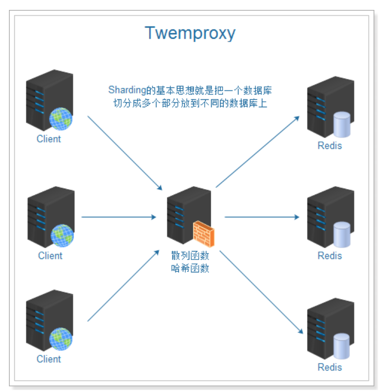
In the figure above, we can see that the main role of the two proxy is the role of the proxy server, which is to partition the database. The fragmentation of the two proxy ensures that the data hash to be stored is stored on the nodes of the cluster and distributed evenly as far as possible. How to implement it involves the consistent hash algorithm, which is commonly used in distributed systems.
2.4.3.2.2 traditional hash scheme
The traditional scheme uses the hash value of the object, takes the modulus of the number of nodes, and then maps them to the corresponding numbered nodes. In this scheme, when the number of nodes changes, the mapping relationship of most objects will fail and need to be migrated.
Hash,Generally, hashing, hashing, or transliteration into hash is the input of any length,Through the hash algorithm, it is transformed into a fixed length output, which is the hash value. The space of hash value is usually much smaller than that of input. Different inputs may be hashed into the same output, so it is impossible to determine the unique input value from the hash value.
In short, it is a function that compresses a message of any length to a message digest of a fixed length.
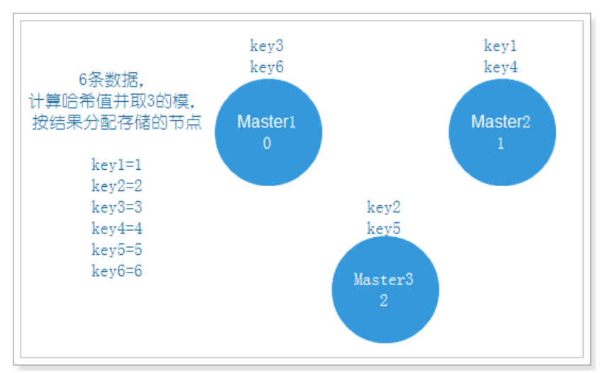
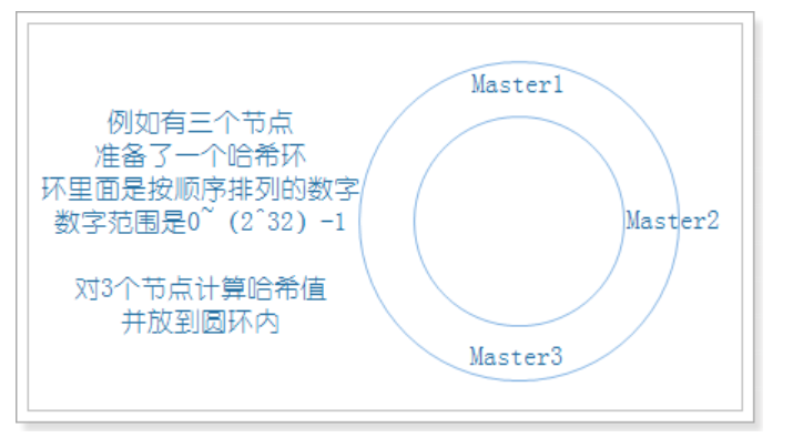
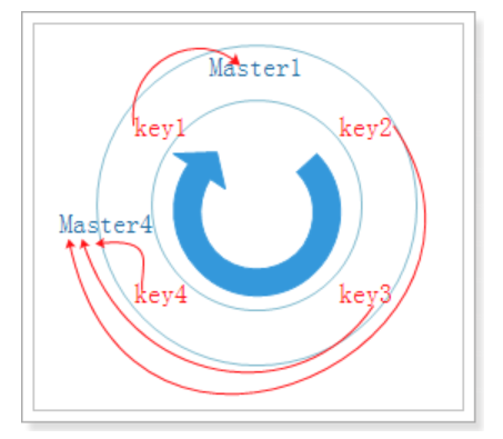
Normally, there are 3 nodes. Take the modulus of 3 and allocate data. The effect is as follows:
If one node is attached, data migration is required to allocate the data to the remaining two nodes, as shown in the following figure:
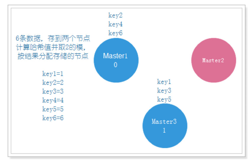
We can see that key3 originally existed on Master1 needs to be migrated to Master3, and Master1 is always normal, which leads to unnecessary data migration and waste of resources. Therefore, we need to adopt another method, consistent hash algorithm.
#####2.4.3.2.3 consistent hash algorithm
Consistent hashing algorithm is a distributed algorithm, which is often used for load balancing. The two proxy also chooses this algorithm to solve the problem of evenly distributing key values to many servers. It can replace the traditional mold taking operation and solve the problem of adding and deleting server.
step
- Firstly, the corresponding node ip is hash ed into a space with 232 (2147483647) buckets, that is, 0 ~ (232) - 1 digital space. Now we can connect these numbers head to tail to form a closed ring:
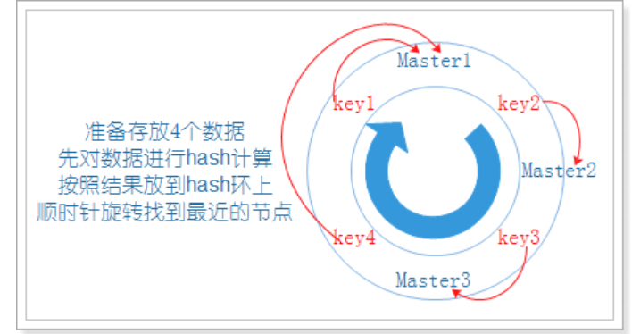
- When the user makes a request on the client, first calculate the routing hash value according to the key, then see where the hash value falls in the hash ring, and find the nearest node clockwise according to the position of the hash value on the hash ring:
-
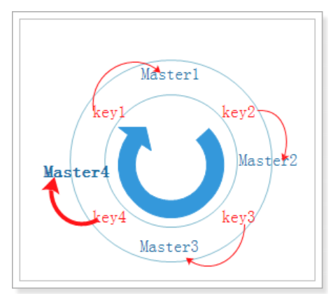
When adding a new node, just migrate the affected data to the new node as before
Add Master4 node:
-
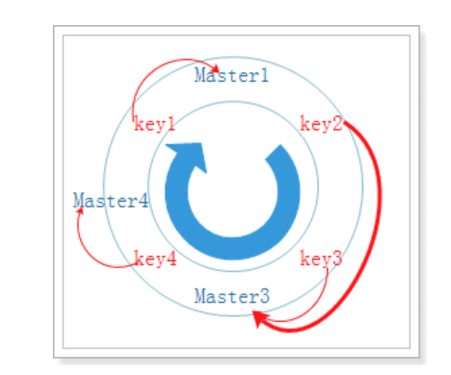
When removing a node, as before, migrate the data of the removed node to the nearest node clockwise
To remove a Master2 node:
As can be seen from the above steps, when the number of nodes changes, there are very few invalid objects using the hash consistency mapping relationship, and the migration cost is very small. So what are the indicators to judge whether a hash algorithm is good or bad? Three indicators are listed below:
-
Balance:
Balance means that the hash results can be distributed to different cache servers as much as possible, so that all servers can be used. Consistent hash can make each server process requests, but it can not guarantee that the number of requests processed by each server is roughly the same
-
Monotonicity:
Monotonicity means that if some requests have been assigned to the corresponding service through hash for processing, and a new server is added to the system, the hash result should ensure that the original request can be mapped to the original or new service, and will not be mapped to other original services.
-
Spread:
In a distributed environment, the client may not know the existence of all servers when requesting, and may only know some of them. In the client's view, some of the services he sees will form a complete hash ring. If multiple clients regard some servers as a complete hash ring, the requests of the same user may be routed to different servers for processing. This situation should obviously be avoided because it can not guarantee that the requests of the same user fall into the same service. The so-called dispersion refers to the severity of the above situation. A good hash algorithm should avoid reducing the dispersion as much as possible. The consistency hash has low dispersion.
2.4.3.2.4 virtual node
After some nodes are offline, although the remaining machines are processing requests, it is obvious that the load of each machine is unbalanced
In order to tilt the consistency hash, virtual nodes appear to solve this problem.
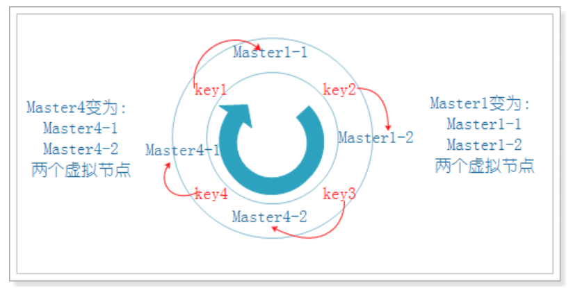
In the example just now, if the Master3 node also hangs, the consistency hash skew is obvious:
It can be seen that in theory, Master1 needs to store 25% of the data, while Master4 needs to store 75% of the data.
In the above example, we can create virtual nodes for two existing nodes, and each node creates two virtual nodes. Then the actual Master1 node becomes two virtual nodes Master1-1 and Master1-2, while the other actual Master4 node becomes two virtual nodes Master4-1 and Master4-2. At this time, the data is basically balanced:
2.4.4 summary
- Through a hash ring, many storage nodes (2 ^ 32-1) are distributed on the ring. When storing data, the key is hashed (hash algorithm) and placed on the nearest node in the clockwise direction. Try to distribute the data evenly
- How to judge whether an algorithm is balanced: balance (whether the data distribution is uniform), monotonicity (ensure that the original remains unchanged, and the new enters the new node), dispersion (whether the distribution will become uneven when the nodes are reduced)
- Use virtual node (the original node virtualizes a new node)
3. Redis cluster environment used in the project [understand]
spring boot RedisTemplate
Application scenario: the mobile terminal system sends the verification code and stores it in redis cluster
[Objective]
1: Redis cluster is used in the project
2: Configuring Redis cluster with spring
[path]
1: Coordinate environment
2: Configuration file
3: Use of RedisTemplate
- Send verification code
- Clean up garbage pictures
[explanation]
3.1. Coordinate environment
Step 1: import spring data redis coordinates
health_parent project
<properties>
	<spring.data.redis>2.1.6.RELEASE</spring.data.redis>
</properties>
<dependency>
  	<groupId>org.springframework.data</groupId>
  	<artifactId>spring-data-redis</artifactId>
  	<version>${spring.data.redis}</version>
</dependency>
health_common subproject
<dependency>
    <groupId>org.springframework.data</groupId>
    <artifactId>spring-data-redis</artifactId>
</dependency>
3.2. Configuration file
Step 1: configure redis
health_ Under resources of mobile project
Configure redis.properties
###redis Cluster push task information cache###
spring.redis.cluster.nodes1.host=192.168.175.129
spring.redis.cluster.nodes1.port=7001
spring.redis.cluster.nodes2.host=192.168.175.129
spring.redis.cluster.nodes2.port=7002
spring.redis.cluster.nodes3.host=192.168.175.129
spring.redis.cluster.nodes3.port=7003
spring.redis.cluster.nodes4.host=192.168.175.129
spring.redis.cluster.nodes4.port=7004
spring.redis.cluster.nodes5.host=192.168.175.129
spring.redis.cluster.nodes5.port=7005
spring.redis.cluster.nodes6.host=192.168.175.129
spring.redis.cluster.nodes6.port=7006
## Redis database index (0 by default)
spring.redis.database=0
## Connection timeout (MS)
spring.redis.timeout=60000
## max retries
spring.redis.maxRedirects=3
## The maximum number of connections in the connection pool (a negative value indicates no limit). If it is a cluster, it is the number of connections per ip
spring.redis.pool.max-active=500
## Maximum blocking wait time of connection pool (negative value indicates no limit)
spring.redis.pool.max-wait=-1
## Maximum free connections in the connection pool
spring.redis.pool.max-idle=300
## Minimum free connections in connection pool
spring.redis.pool.min-idle=100
Step 2: configure spring-redis.xml
<?xml version="1.0" encoding="UTF-8"?>
<beans xmlns="http://www.springframework.org/schema/beans"
xmlns:xsi="http://www.w3.org/2001/XMLSchema-instance"
xmlns:context="http://www.springframework.org/schema/context"
xmlns:dubbo="http://code.alibabatech.com/schema/dubbo"
xmlns:mvc="http://www.springframework.org/schema/mvc"
xsi:schemaLocation="http://www.springframework.org/schema/beans
http://www.springframework.org/schema/beans/spring-beans.xsd
http://www.springframework.org/schema/mvc
http://www.springframework.org/schema/mvc/spring-mvc.xsd
http://code.alibabatech.com/schema/dubbo
http://code.alibabatech.com/schema/dubbo/dubbo.xsd
http://www.springframework.org/schema/context
http://www.springframework.org/schema/context/spring-context.xsd">
<!--load redis.properties constant configuration -->
<context:property-placeholder location="classpath:redis.properties"></context:property-placeholder>
<!-- redis Cluster start -->
<!-- redis template definition -->
<bean id="redisTemplate" class="org.springframework.data.redis.core.RedisTemplate">
<property name="connectionFactory" ref="jedisConnectionFactory" />
<property name="keySerializer">
<bean class="org.springframework.data.redis.serializer.StringRedisSerializer" />
</property>
<property name="valueSerializer">
<bean class="org.springframework.data.redis.serializer.JdkSerializationRedisSerializer" />
</property>
<property name="hashKeySerializer">
<bean class="org.springframework.data.redis.serializer.StringRedisSerializer" />
</property>
<property name="hashValueSerializer">
<bean class="org.springframework.data.redis.serializer.JdkSerializationRedisSerializer" />
</property>
</bean>
<!-- Spring-redis Connection pool management factory -->
<bean id="jedisConnectionFactory" class="org.springframework.data.redis.connection.jedis.JedisConnectionFactory" destroy-method="destroy">
<constructor-arg ref="redisClusterConfiguration" />
<constructor-arg ref="jedisPoolConfig" />
<!-- Redis Database index(The default is 0) -->
<property name="database" value="${spring.redis.database}"/>
</bean>
<!-- Cluster configuration -->
<bean id="redisClusterConfiguration" class="org.springframework.data.redis.connection.RedisClusterConfiguration">
<property name="clusterNodes">
<set>
<ref bean="clusterRedisNodes1"/>
<ref bean="clusterRedisNodes2"/>
<ref bean="clusterRedisNodes3"/>
<ref bean="clusterRedisNodes4"/>
<ref bean="clusterRedisNodes5"/>
<ref bean="clusterRedisNodes6"/>
</set>
</property>
<property name="maxRedirects" value="${spring.redis.maxRedirects}" />
</bean>
<!-- Cluster node -->
<bean id="clusterRedisNodes1" class="org.springframework.data.redis.connection.RedisNode">
<constructor-arg value="${spring.redis.cluster.nodes1.host}" />
<constructor-arg value="${spring.redis.cluster.nodes1.port}" type="int" />
</bean>
<bean id="clusterRedisNodes2" class="org.springframework.data.redis.connection.RedisNode">
<constructor-arg value="${spring.redis.cluster.nodes2.host}" />
<constructor-arg value="${spring.redis.cluster.nodes2.port}" type="int" />
</bean>
<bean id="clusterRedisNodes3" class="org.springframework.data.redis.connection.RedisNode">
<constructor-arg value="${spring.redis.cluster.nodes3.host}" />
<constructor-arg value="${spring.redis.cluster.nodes3.port}" type="int" />
</bean>
<bean id="clusterRedisNodes4" class="org.springframework.data.redis.connection.RedisNode">
<constructor-arg value="${spring.redis.cluster.nodes4.host}" />
<constructor-arg value="${spring.redis.cluster.nodes4.port}" type="int" />
</bean>
<bean id="clusterRedisNodes5" class="org.springframework.data.redis.connection.RedisNode">
<constructor-arg value="${spring.redis.cluster.nodes5.host}" />
<constructor-arg value="${spring.redis.cluster.nodes5.port}" type="int" />
</bean>
<bean id="clusterRedisNodes6" class="org.springframework.data.redis.connection.RedisNode">
<constructor-arg value="${spring.redis.cluster.nodes6.host}" />
<constructor-arg value="${spring.redis.cluster.nodes6.port}" type="int" />
</bean>
<!-- Cluster node -->
<!--<!– redis End of cluster –>-->
<bean id="jedisPoolConfig" class="redis.clients.jedis.JedisPoolConfig">
<property name="maxTotal" value="${spring.redis.pool.max-active}" />
<property name="maxIdle" value="${spring.redis.pool.max-idle}" />
<property name="minIdle" value="${spring.redis.pool.min-idle}" />
<property name="maxWaitMillis" value="${spring.redis.pool.max-wait}" />
<property name="testOnBorrow" value="true" />
<property name="testOnReturn" value="true"/>
</bean>
</beans>
Step 3: springmvc.xml
Introduce spring-redis.xml
<import resource="classpath:spring-redis.xml"></import>
3.3. Use of redistemplate
3.3.1 send verification code
Step 1: modify ValidateCode mobilecontroller to store Redis data
@Autowired
RedisTemplate redisTemplate;

@RequestMapping(value = "/send4Order")
public Result send4Order(String telephone){
        ...
        redisTemplate.opsForValue().set(telephone+ RedisMessageConstant.SENDTYPE_ORDER,code4.toString(),5, TimeUnit.MINUTES);
}

@RequestMapping(value = "/send4Login")
public Result send4Login(String telephone){
        ...
        redisTemplate.opsForValue().set(telephone+ RedisMessageConstant.SENDTYPE_LOGIN,code4.toString(),5, TimeUnit.MINUTES);
}
Step 2: modify OrderMobileController to obtain Redis data
@Autowired
RedisTemplate redisTemplate;

// Submit reservation saving
@RequestMapping(value = "/submit")
public Result sumbit(@RequestBody Map map){
    ...
    String redisValidateCode = (String) redisTemplate.opsForValue().get(telephone + RedisMessageConstant.SENDTYPE_ORDER);
}
Step 3: modify loginmobile controller to obtain Redis data
@Autowired
private RedisTemplate redisTemplate;

// Login verification
@RequestMapping(value = "/check")
public Result sumbit(@RequestBody Map map, HttpServletResponse response){
    ...
    String redisValidateCode = (String) redisTemplate.opsForValue().get(telephone + RedisMessageConstant.SENDTYPE_LOGIN);
}
Start healthmobile_web, use the mobile phone number to log in to the page, obtain the verification code, and complete the function test
3.3.1 garbage cleaning picture [no need]
Step 1: configuration file
1: Copy redis.properties and spring-redis.xml to health_ In the web
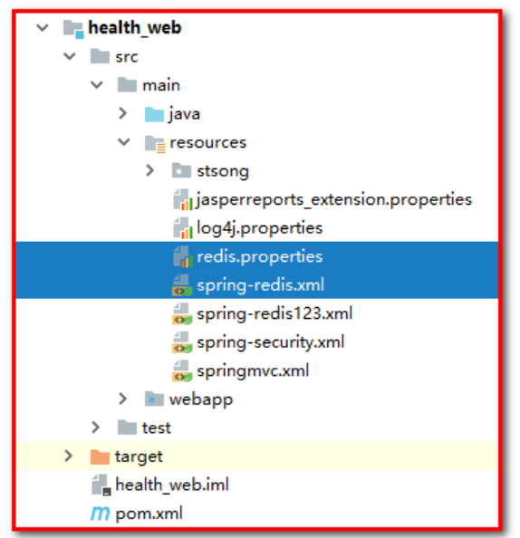
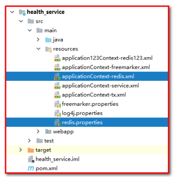
2: Copy redis.properties and spring-redis.xml to health_ In the service, change the name of spring-redis.xml to applicationContext-redis.xml
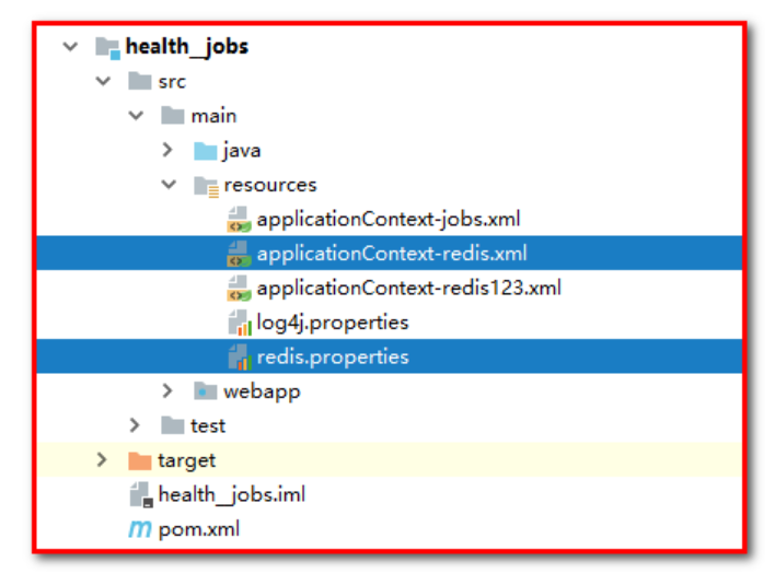
3: Copy redis.properties and spring-redis.xml to health_ In jobs, change the name of spring-redis.xml to applicationContext-redis.xml
Step 2: modify SetmealServiceImpl.java to store Redis data, save the database and store the picture name at the same time
@Autowired
RedisTemplate redisTemplate;

// Save package data
@Override
public void add(Setmeal setmeal, Integer[] checkgroupIds) {
  	// 1: Add a new package and add a piece of data to the package table
  	setmealDao.add(setmeal);
    // 2: Add the intermediate table of package and inspection group. You want to insert multiple data into the intermediate table of package and inspection group
    if(checkgroupIds!=null && checkgroupIds.length>0){
      	setSetmealAndCheckGroup(setmeal.getId(),checkgroupIds);
    }
    // 3: Save data to the key value of the set in Redis as setmealPicDbResources. The data is the name of the picture
    //jedisPool.getResource().sadd(RedisConstant.SETMEAL_PIC_DB_RESOURCES,setmeal.getImg());
    redisTemplate.opsForSet().add(RedisConstant.SETMEAL_PIC_DB_RESOURCES,setmeal.getImg());

    //After adding a package, you need to regenerate the static page
    generateMobileStaticHtml();
}


//When editing the package, you need to update and check the association relationship of the group
@Override
public void edit(Setmeal setmeal, Integer[] checkgroupIds) {
    // Use the package id to query the package corresponding to the database and obtain the img stored in the database
    Setmeal setmeal_db = setmealDao.findById(setmeal.getId());
    String img = setmeal_db.getImg();
    // If the picture name passed on the page is inconsistent with the picture name stored in the database, it indicates that the picture is updated and the picture in the database before qiniu cloud needs to be deleted
    if(setmeal.getImg()!=null && !setmeal.getImg().equals(img)){
      	QiniuUtils.deleteFileFromQiniu(img);
      	//Delete the picture name from Redis, and the key value is setmealPicDbResources
     //jedisPool.getResource().srem(RedisConstant.SETMEAL_PIC_DB_RESOURCES,img);
      redisTemplate.opsForSet().remove(RedisConstant.SETMEAL_PIC_DB_RESOURCES,img);
      	//Delete the picture name from Redis, and the key value is setmealPicResources
      	//jedisPool.getResource().srem(RedisConstant.SETMEAL_PIC_RESOURCES,img);
      redisTemplate.opsForSet().remove(RedisConstant.SETMEAL_PIC_RESOURCES,img);
    }

    //1: Delete the intermediate table data according to the package id (clean up the original association relationship)
    setmealDao.deleteAssociation(setmeal.getId());
    //2: Insert data into the intermediate table (t_setmeal_checkgroup) (establish the relationship between package and check group)
    setSetmealAndCheckGroup(setmeal.getId(),checkgroupIds);
    //3: Update package basic information
    setmealDao.edit(setmeal);
}

// Delete package
@Override
public void deleteById(Integer id) {
  	// Use the package id to query the package corresponding to the database and obtain the img stored in the database
  	Setmeal setmeal_db = setmealDao.findById(id);

  	// Use the package id to query the package and inspection group intermediate table
    Integer count = setmealDao.findSetmealAndCheckGroupCountBySetmealId(id);
    // Existing data
    if(count>0){
      	throw new RuntimeException("There is an association relationship between the current package and the inspection group, which cannot be deleted");
    }
    // Delete package
    setmealDao.deleteById(id);

    // Get stored picture information
    String img = setmeal_db.getImg();
    // You need to delete the image in the database before qiniu cloud
    if(img!=null && !"".equals(img)){
      	QiniuUtils.deleteFileFromQiniu(img);
      	//Delete the picture name from Redis, and the key value is setmealPicDbResources
     //jedisPool.getResource().srem(RedisConstant.SETMEAL_PIC_DB_RESOURCES,img);
      redisTemplate.opsForSet().remove(RedisConstant.SETMEAL_PIC_DB_RESOURCES,img);
      	//Delete the picture name from Redis, and the key value is setmealPicResources
      	//jedisPool.getResource().srem(RedisConstant.SETMEAL_PIC_RESOURCES,img);
      redisTemplate.opsForSet().remove(RedisConstant.SETMEAL_PIC_RESOURCES,img);
    }
}
Modify SetmealController.java to store Redis data, upload pictures and store picture names at the same time
	@Autowired
	RedisTemplate redisTemplate;

    // Upload of package pictures (file upload of spring MVC)
    @RequestMapping(value = "/upload")
    public Result upload(MultipartFile imgFile){
        try {
            // Previous file name
            String fileName = imgFile.getOriginalFilename();
            // Use the form of UUID (timestamp) to ensure that the file name is unique
            fileName = UUID.randomUUID().toString()+fileName.substring(fileName.lastIndexOf("."));
            // Upload from qiniu cloud
            QiniuUtils.upload2Qiniu(imgFile.getBytes(),fileName);
            // At the same time, store data and file name to the key=setmealPicResource of the set in Redis
            // jedisPool.getResource().sadd(RedisConstant.SETMEAL_PIC_RESOURCES,fileName);
            redisTemplate.opsForSet().add(RedisConstant.SETMEAL_PIC_RESOURCES,fileName);
            // Response file name
            return new Result(true, MessageConstant.PIC_UPLOAD_SUCCESS,fileName);
        } catch (Exception e) {
            e.printStackTrace();
            return new Result(false, MessageConstant.PIC_UPLOAD_FAIL);
        }
    }
Step 3: modify health_jobs and use scheduled tasks to remove garbage pictures.
// Task class
public class ClearImgJob {

//    @Autowired
//    JedisPool jedisPool;

    @Autowired
    RedisTemplate redisTemplate;

    // Method of task class execution
    public void executeJob(){
        //Calculate the difference between the setmealPicResources set and the setmealPicDbResources set, and clean up the picture
        // Set<String> set = jedisPool.getResource().sdiff(RedisConstant.SETMEAL_PIC_RESOURCES, RedisConstant.SETMEAL_PIC_DB_RESOURCES);
        Set<String> set = redisTemplate.opsForSet().difference(RedisConstant.SETMEAL_PIC_RESOURCES, RedisConstant.SETMEAL_PIC_DB_RESOURCES);
        Iterator<String> iterator = set.iterator();
        while(iterator.hasNext()){
            String picName = iterator.next();
            System.out.println("Deleted picture name:"+picName);
            // 1: Delete the data of qiniu cloud
            QiniuUtils.deleteFileFromQiniu(picName);
            // 2: : delete redis data whose key value is ssetmealPicResources
            //jedisPool.getResource().srem(RedisConstant.SETMEAL_PIC_RESOURCES,picName);
            redisTemplate.opsForSet().remove(RedisConstant.SETMEAL_PIC_RESOURCES,picName);
        }

    }
}
Start the health_job and use the scheduled task to clean up garbage pictures.
Summary
1: Coordinate environment
2: The configuration file is cumbersome and will become very simple when integrated with spring boot in the future
3: RedisTemplate opsForValue (bit, String) opsForSet operation set
- Send verification code
- Clean up garbage pictures
Project Description:
Development environment and Application Technology:
Responsibility description:
Technical description: