Preface
After studying for so long from 51 to STM32F4, I finally got a clue. Now I have learned the basic usage of GPIO, interrupt, timer and watchdog, so I want to try to see if I can do something, that is, to review the knowledge I have learned recently. Just last semester, MCU curriculum design has done a clock with Bluetooth, button calibration and temperature display, so I want to see if I can transplant the program to STM32? After three days of modification and debugging, we finally succeeded!
Because the accuracy of STM32 internal timer is still very high (one hour slower than one second), so there is no use of DS1302 clock chip (the key is not in hand). The display is somewhat different from the curriculum design. There is no additional date and week display, on the time, alarm clock and temperature display.
Introduction of 1602 Liquid Crystal
Industrial character LCD can display 16x02 or 32 characters at the same time. 1602 liquid crystal is also called 1602 character liquid crystal. It is a dot matrix liquid crystal module used to display letters, numbers, symbols and so on. It consists of several 5X7 or 5X11 dot-matrix character bits. Each dot-matrix character bit can display a character. There is a dot-space interval between each bit, and there is a space between each line. It plays the role of CHARACTER-SPACE and line-space. Because of this, it can not display graphics well (with custom CGRAM, display). The effect is not good either. Most character liquid crystals on the market are based on HD44780 LCD chip. The control principle is the same. Therefore, the control program written on HD44780 can be easily applied to most character liquid crystals on the market. 1602 LCD refers to the content of the display is 16X2, that is, it can display two lines, each line of 16 characters LCD module (display characters and numbers).
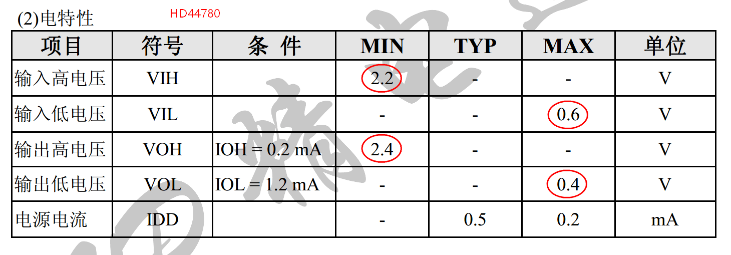
Visible with STM32 3.3v level drive display is completely no problem, I am relieved to see that, after many modifications, the code finally succeeded in showing, so we still need to look at the data manual.
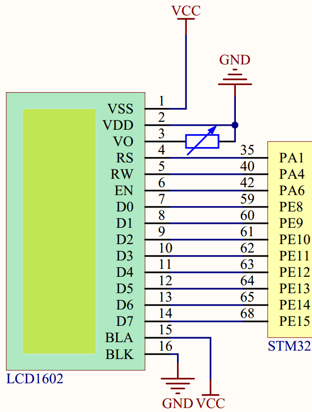
Hardware Circuit Connection
Programming
1. The macro definition of control line can be operated by bit band operation, and then RS=1 like 51 can be operated. Is it very familiar? The eight ports of the data line are also defined as an LCD_DB.
#define LCD_RS PAout(1)
#define LCD_RW PAout(4)
#define LCD_EN PAout(6)
#define LCD_DB GPIO_Pin_8 | GPIO_Pin_9 | GPIO_Pin_10 | GPIO_Pin_11 |GPIO_Pin_12 | GPIO_Pin_13 | GPIO_Pin_14 | GPIO_Pin_15
2. The GPIO configuration connected with LCD, which configures the data line port to OD output mode, can be used as bidirectional IO. When checking whether the LCD is busy, it needs to read the state of D7 bits.
void LCD_GPIO_Config(void)
{
    GPIO_InitTypeDef  IO_Init;

    RCC_AHB1PeriphClockCmd(RCC_AHB1Periph_GPIOA | RCC_AHB1Periph_GPIOE,ENABLE);

    /*Control line initialization: */
    IO_Init.GPIO_Mode=GPIO_Mode_OUT;        //output
    IO_Init.GPIO_OType=GPIO_OType_PP;        //push-pull mode
    IO_Init.GPIO_Pin=GPIO_Pin_1 | GPIO_Pin_4 | GPIO_Pin_6;
    IO_Init.GPIO_PuPd=GPIO_PuPd_UP;            //
    IO_Init.GPIO_Speed=GPIO_Speed_2MHz;        //GPIO_Speed_2MHz
    GPIO_Init(GPIOA,&IO_Init);

    /*Data line initialization*/
    IO_Init.GPIO_Mode=GPIO_Mode_OUT;
    IO_Init.GPIO_OType=GPIO_OType_OD;        //Leakage output can be bidirectional
    IO_Init.GPIO_Pin=LCD_DB;
    IO_Init.GPIO_PuPd=GPIO_PuPd_UP;            //Pull up
    IO_Init.GPIO_Speed=GPIO_Speed_2MHz;
    GPIO_Init(GPIOE,&IO_Init);
    /*Testing: High level 3.3v
    LCD_RS=1;
    LCD_RW=1;
    LCD_EN=1;
    GPIO_SetBits(GPIOE,LCD_DB); */
}
3. Function of P1=0xff with parameters
void GPIO_OutData(u8 Dat)
{
    u16 tmp;
    tmp = 0;
    tmp =Dat;
    tmp <<= 8;            //Move data left to 8 bits high
    GPIO_Write(GPIOE,tmp);        //Data written to GPIOE 8 bits high
}
4. Check if LCD is busy
void LCD_CheckBusy(void)
{
    u8 sta;
    GPIO_OutData(0xff);
    LCD_RS=0;
    LCD_RW=1;
    do{
        LCD_EN=1;
        delay_ms(5);
        sta = GPIO_ReadInputDataBit(GPIOE,GPIO_Pin_15);
        LCD_EN =0;
    }while(sta & 0x80);
}
5. Write a byte of data to the LCD
/* LCD_RS = 1, LCD_RW = 0 */
void LCD_WriteData(u8 Dat)
{

    LCD_CheckBusy(); //Busy is waiting
    LCD_RS=1;
    LCD_RW=0;
    GPIO_OutData(Dat);
    LCD_EN=1;
    delay_ms(1);
    LCD_EN = 0;

}
6. Write a byte command to the LCD
/*LCD_RS = 0, LCD_RW = 0*/
void LCD_WriteCmd(u8 Cmd)
{
    LCD_CheckBusy(); //Busy is waiting
    LCD_RS = 0;
    LCD_RW = 0;
    GPIO_OutData(Cmd);
    LCD_EN = 1;
    delay_ms(1);
    LCD_EN = 0;
}
7.LCD initialization
void LCD_Init(void)
{
    LCD_WriteCmd(0x38);
    LCD_WriteCmd(0x0C);
    LCD_WriteCmd(0x06);    /*Display cursor movement settings*/    delay_ms(1);
    LCD_WriteCmd(0x01);    /*Display Clear Screen*/
}
8.LCD Screen Cleaning
void LCD_ClearScrren(void)
{
    LCD_WriteCmd(0x01);
}
9. Write the corresponding data location according to xy coordinates
void LCD_SetCursor(u8 x, u8 y)
{
    u8 addr;
    if (y == 0)
        addr = 0x00 + x;
    else
        addr = 0x40 + x;
    LCD_WriteCmd(addr | 0x80);
}
10. Display a character according to xy coordinates
void LCD_DisChar(u8 x,u8 y,u8 ch)
{
    LCD_SetCursor(x,y);        //Character Display Position Setting
    LCD_WriteData(ch);
}
11. Display two digits
void LCD_DisNumber(u8 x,u8 y,u8 Num)
{
    LCD_SetCursor(x,y);
    LCD_WriteData(0x30+Num/10);
    LCD_SetCursor(x+1,y);
    LCD_WriteData(0x30+Num%10);
}
12. Display string
void LCD_DisString(u8 x,u8 y,u8 *str)
{
    LCD_SetCursor(x, y);
    while(*str != '\0')
    {
        LCD_WriteData(*str++);
    }
}
Principal function
int main(void)
{
    delay_init(168);
    LED_Init();

    LCD_GPIO_Config();
    LCD_Init();
    LCD_ClearScrren();
    while(1)
    {
        delay_ms(500);
        LED1_ON;
        LCD_DisString(0,0,"abcdefghijklmnop");
        delay_ms(500);
        LED1_OFF;
        LCD_DisNumber(0,1,56);
        LCD_DisChar(2,1,'a');
        LCD_DisString(3,1," Hello World!");
    }
}
Actual display effect:
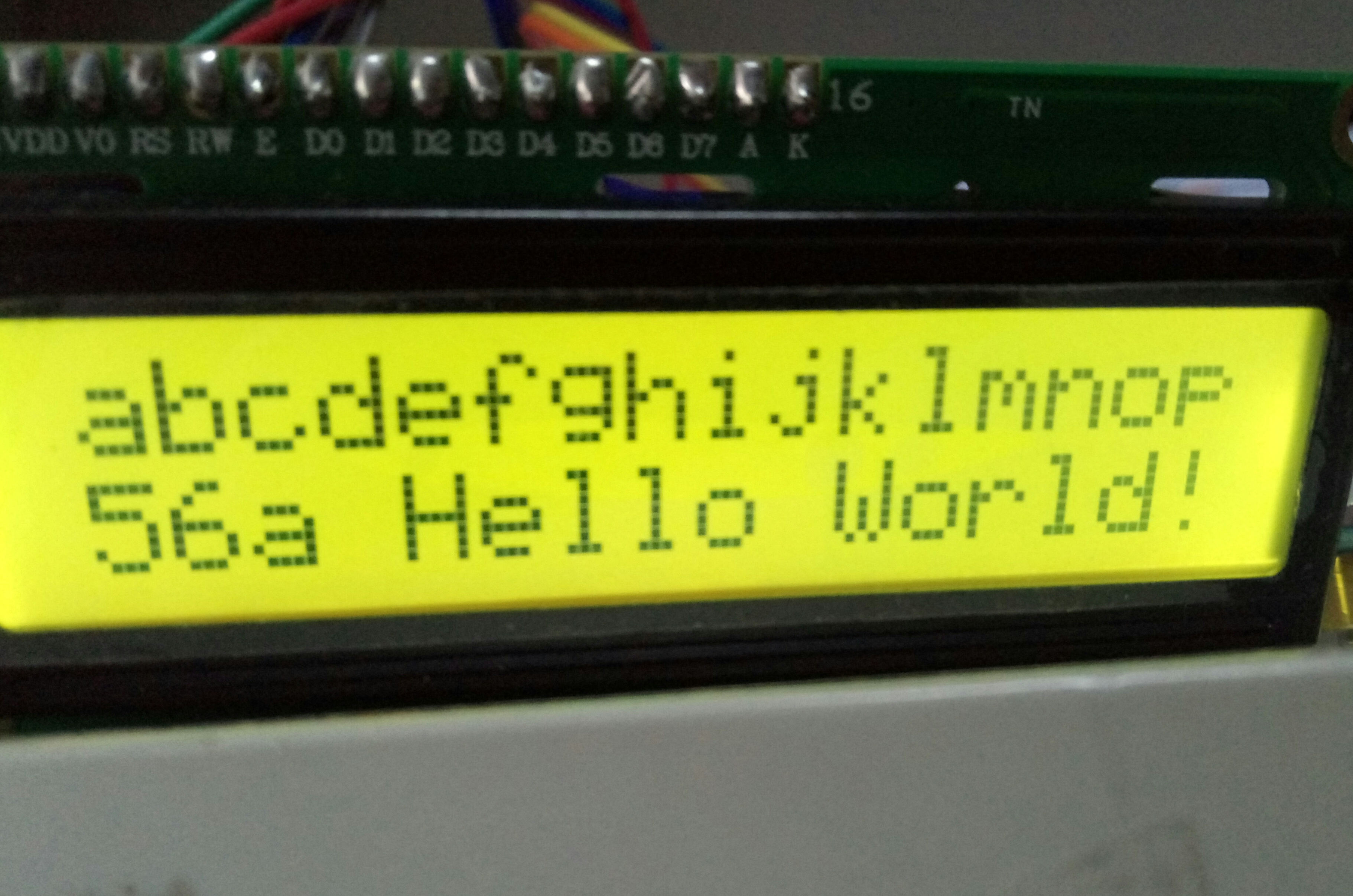
Perfect display, no difference from 51 driver