The author introduces: Jiang Xue Wei Technological Partner of IT Company, Senior IT Lecturer, CSDN Community Expert, Invited Editor, Best-selling Book Author; Published Book: Hand-to-Hand Teaching Framework 3D Game Engine. Electronic Industry Press and< Unity3D Detailed Explanation of Actual Core Technologies, Electronic Industry Press, etc.
CSDN Video Website: http://edu.csdn.net/lecturer/144
Dynamic shadows are created in Shadow Mapping, and the effect meets the requirement, but they are only suitable for directional light, because shadows are only generated by a single directional light source, sometimes called directional Shadow Mapping, and shadow maps generate a view of self-directional light.
In this blog, we mainly introduce how to generate dynamic shadows in various directions. This technology can be applied to point light sources and can generate shadows in all directions. This technology is called point shadows.
If you're not familiar with traditional Shadow Mapping, it's better to read the Shadow Mapping blog first. The algorithm is similar to directed Shadow Mapping: we generate a depth map from the perspective of light, sample the depth map based on the current fragment location, and then compare the stored depth values with each fragment to see if it is in shadow. The main difference between directional Shadow Mapping and point shadow is the use of depth mapping.
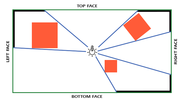
For depth mapping, we need to render all scenes from a point light source. Normal 2D depth mapping does not work; what if we use cube mapping? Because cube mapping can store environment data of six faces, it can render the whole scene to each face of cube mapping, and use them as depth values around point light source to sample.
The generated depth cube map is transferred to the illuminated pixel shader, which uses a directional vector to sample the cube map to get the current fragment depth (from the perspective of light). Most of the complex things have been discussed in the Shadow Mapping tutorial. The algorithm is only slightly more complex in generating deep cube maps.
To create a cube map of the depth around the light, we have to render the scene six times: one face at a time. Obviously, six different view matrices are needed to render the scene six times, each time a different cube mapping surface is attached to the frame buffer object. It looks like this:
for(int i = 0; i < 6; i++)
{
    GLuint face = GL_TEXTURE_CUBE_MAP_POSITIVE_X + i;
    glFramebufferTexture2D(GL_FRAMEBUFFER, GL_DEPTH_ATTACHMENT, face, depthCubemap, 0);
    BindViewMatrix(lightViewMatrices[i]);
    RenderScene();
}
This can be performance-intensive because many rendering calls are required under a depth map. In this tutorial, we'll turn to another trick to do this. Geometric shaders allow us to use a rendering process to create depth cube maps.
First, we need to create a cube map:
Then each face of cube mapping is generated as a 2D depth value texture image:GLuint depthCubemap; glGenTextures(1, &depthCubemap);
const GLuint SHADOW_WIDTH = 1024, SHADOW_HEIGHT = 1024;
glBindTexture(GL_TEXTURE_CUBE_MAP, depthCubemap);
for (GLuint i = 0; i < 6; ++i)
        glTexImage2D(GL_TEXTURE_CUBE_MAP_POSITIVE_X + i, 0, GL_DEPTH_COMPONENT,
SHADOW_WIDTH, SHADOW_HEIGHT, 0, GL_DEPTH_COMPONENT, GL_FLOAT, NULL);Normally, we attach one side of the cube map texture to the frame buffer object, render the scene six times, and change the depth buffer object of the frame buffer into different cube map surface each time. Since we will use a geometric shader, which allows us to render all faces in one process, we can use glFramebuffer Texture to attach cube maps directly to frame buffer depth attachments:glTexParameteri(GL_TEXTURE_CUBE_MAP, GL_TEXTURE_MAG_FILTER, GL_NEAREST); glTexParameteri(GL_TEXTURE_CUBE_MAP, GL_TEXTURE_MIN_FILTER, GL_NEAREST); glTexParameteri(GL_TEXTURE_CUBE_MAP, GL_TEXTURE_WRAP_S, GL_CLAMP_TO_EDGE); glTexParameteri(GL_TEXTURE_CUBE_MAP, GL_TEXTURE_WRAP_T, GL_CLAMP_TO_EDGE); glTexParameteri(GL_TEXTURE_CUBE_MAP, GL_TEXTURE_WRAP_R, GL_CLAMP_TO_EDGE);
glBindFramebuffer(GL_FRAMEBUFFER, depthMapFBO);
glFramebufferTexture(GL_FRAMEBUFFER, GL_DEPTH_ATTACHMENT, depthCubemap, 0);
glDrawBuffer(GL_NONE);
glReadBuffer(GL_NONE);
glBindFramebuffer(GL_FRAMEBUFFER, 0);
Also remember to call glDrawBuffer and glReadBuffer: When generating a depth cube map, we only care about the depth value, so we have to explicitly tell OpenGL that the frame buffer object will not be rendered into a color buffer.
Universal Shadow Mapping has two rendering stages: first, we generate depth mapping, then we use depth mapping to render and create shadows in the scene. The processing of frame buffer objects and cube maps looks like this:
// 1. first render to depth cubemap
glViewport(0, 0, SHADOW_WIDTH, SHADOW_HEIGHT);
glBindFramebuffer(GL_FRAMEBUFFER, depthMapFBO);
    glClear(GL_DEPTH_BUFFER_BIT);
    ConfigureShaderAndMatrices();
    RenderScene();
glBindFramebuffer(GL_FRAMEBUFFER, 0);
// 2. then render scene as normal with shadow mapping (using depth cubemap)
glViewport(0, 0, SCR_WIDTH, SCR_HEIGHT);
glClear(GL_COLOR_BUFFER_BIT | GL_DEPTH_BUFFER_BIT);
ConfigureShaderAndMatrices();
glBindTexture(GL_TEXTURE_CUBE_MAP, depthCubemap);
RenderScene();With frame buffering and cube mapping, we need some methods to transform all the geometries of the scene into the corresponding light space in the direction of six lights. Similar to the Shadow Mapping blog post, we will need a transformation matrix T in the light space, but this time there is one for each side.
The transformation matrix of each optical space includes the projection matrix and the view matrix. For the projection matrix, we will use a perspective projection matrix; the light source represents a point in a space, so the perspective projection matrix is more meaningful. Each optical space transformation matrix uses the same projection matrix:
GLfloat aspect = (GLfloat)SHADOW_WIDTH/(GLfloat)SHADOW_HEIGHT;
GLfloat near = 1.0f;
GLfloat far = 25.0f;
glm::mat4 shadowProj = glm::perspective(glm::radians(90.0f), aspect, near, far);
It's very important that the field of view parameter glm::perspective is set to 90 degrees. Only at 90 degrees can we ensure that the field of vision is large enough to fill one face of the cube map appropriately, and that all the faces of the cube map can be aligned with the edges of other faces.
Because the projection matrix does not change in each direction, we can reuse it in six transformation matrices. We need to provide a different view matrix for each direction. Create six observation directions with glm:: look at at at Atlas, each looking at one direction of cube mapping in sequence: right, left, up, down, near and far:
std::vector<glm::mat4> shadowTransforms;
shadowTransforms.push_back(shadowProj *
                 glm::lookAt(lightPos, lightPos + glm::vec3(1.0,0.0,0.0), glm::vec3(0.0,-1.0,0.0));
shadowTransforms.push_back(shadowProj *
                 glm::lookAt(lightPos, lightPos + glm::vec3(-1.0,0.0,0.0), glm::vec3(0.0,-1.0,0.0));
shadowTransforms.push_back(shadowProj *
                 glm::lookAt(lightPos, lightPos + glm::vec3(0.0,1.0,0.0), glm::vec3(0.0,0.0,1.0));
shadowTransforms.push_back(shadowProj *
                 glm::lookAt(lightPos, lightPos + glm::vec3(0.0,-1.0,0.0), glm::vec3(0.0,0.0,-1.0));
shadowTransforms.push_back(shadowProj *
                 glm::lookAt(lightPos, lightPos + glm::vec3(0.0,0.0,1.0), glm::vec3(0.0,-1.0,0.0));
shadowTransforms.push_back(shadowProj *
                 glm::lookAt(lightPos, lightPos + glm::vec3(0.0,0.0,-1.0), glm::vec3(0.0,-1.0,0.0));
Here we create six view matrices and multiply them by projection matrices to get six different optical space transformation matrices. Glm:: The target parameter of lookAt is one of the directions it looks at on the surface of the stereo map.
These transformation matrices are sent to the shader to render the cube map.
To render values to depth cube maps, we will need three shaders: vertex and pixel shaders, and a geometric shader between them.
Geometric shaders are shaders responsible for transforming vertices of all world spaces into six different light spaces. Therefore, vertex shaders simply transform vertices into world space and send them directly to geometric shaders:
#version 330 core
layout (location = 0) in vec3 position;

uniform mat4 model;

void main()
{
    gl_Position = model * vec4(position, 1.0);
}
Next, the geometric shader takes the vertices of three triangles as input, and it also has a uniform array of optical space transformation matrices. The geometric shader will then be responsible for converting vertices into light space; here it begins to be interesting.
The geometric shader has a built-in variable called gl_Layer, which specifies which side of the cube map the basic graph emits. When it is ignored, the geometric shader sends its basic graphics to the next stage of the pipeline as usual, but when we update this variable, we can control which side of the cube map each basic graphics will render. Of course, this only works when we have a cube texture attached to the active frame buffer:
#version 330 core
layout (triangles) in;
layout (triangle_strip, max_vertices=18) out;

uniform mat4 shadowMatrices[6];

out vec4 FragPos; // FragPos from GS (output per emitvertex)

void main()
{
    for(int face = 0; face < 6; ++face)
    {
        gl_Layer = face; // built-in variable that specifies to which face we render.
        for(int i = 0; i < 3; ++i) // for each triangle's vertices
        {
            FragPos = gl_in[i].gl_Position;
            gl_Position = shadowMatrices[face] * FragPos;
            EmitVertex();
        }
        EndPrimitive();
    }
}
Geometric shaders are relatively simple. We input a triangle and output a total of six triangles (6*3 vertices, so a total of 18 vertices). In the main function, we traverse six faces of the cube map, each of which is designated as an output surface, and store the interger (integer) of the face to gl_Layer. Then, by multiplying the light space transformation matrix of the plane by FragPos, each vertex of the world space is transformed into the relevant light space, and each triangle is generated. Note that we also send the final FragPos variable to the pixel shader, and we need to calculate a depth value.
In the last tutorial, we used an empty pixel shader to configure the depth value of the depth map in OpenGL. This time we will calculate our own depth, which is the linear distance between each fragment position and the light source position. Calculating their own depth makes the shadow calculation more intuitive.
#version 330 core
in vec4 FragPos;

uniform vec3 lightPos;
uniform float far_plane;

void main()
{
    // get distance between fragment and light source
    float lightDistance = length(FragPos.xyz - lightPos);

    // map to [0;1] range by dividing by far_plane
    lightDistance = lightDistance / far_plane;

    // Write this as modified depth
    gl_FragDepth = lightDistance;
}
The pixel shader takes FragPos from the geometric shader, the position vector of light and the far-plane value of the cone as input. Here we map the distance between the fragment and the light source to a range of 0 to 1, and write it into the depth value of the fragment.
Using these shaders to render the scene, after the additional frame buffer object of the cube map is activated, you will get a fully filled depth cube map for the second stage of shadow calculation.
Now that all the preparations have been made, let's introduce some shadows. This process is similar to the directed Shadow Mapping blog post, although this time the depth map we bind is a cube map, not a 2D texture, and the far plane of the projection of light is sent to the shader.glViewport(0, 0, SCR_WIDTH, SCR_HEIGHT); glClear(GL_COLOR_BUFFER_BIT | GL_DEPTH_BUFFER_BIT); shader.Use(); // ... send uniforms to shader (including light's far_plane value) glActiveTexture(GL_TEXTURE0); glBindTexture(GL_TEXTURE_CUBE_MAP, depthCubemap); // ... bind other textures RenderScene();
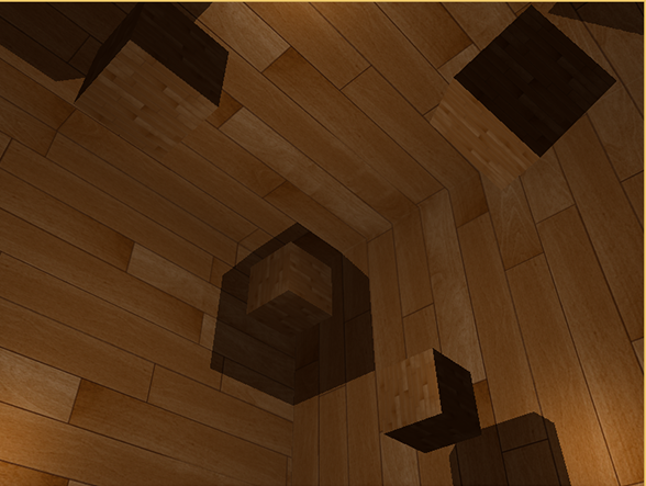
The renderScene function here renders some cubes in a large cube room. They are scattered all over the big cube and the light source is in the center of the scene.
Vertex shader and pixel shader are mostly the same as the original Shadow Mapping shader: the difference is that the pixel shader no longer needs a fragment position in the optical space, and now we can use a direction vector to sample depth values.
Because this vertex shader no longer needs to transform its position vector into optical space, we can remove the FragPosLightSpace variable:
#version 330 core
layout (location = 0) in vec3 position;
layout (location = 1) in vec3 normal;
layout (location = 2) in vec2 texCoords;

out vec2 TexCoords;

out VS_OUT {
    vec3 FragPos;
    vec3 Normal;
    vec2 TexCoords;
} vs_out;

uniform mat4 projection;
uniform mat4 view;
uniform mat4 model;

void main()
{
    gl_Position = projection * view * model * vec4(position, 1.0f);
    vs_out.FragPos = vec3(model * vec4(position, 1.0));
    vs_out.Normal = transpose(inverse(mat3(model))) * normal;
    vs_out.TexCoords = texCoords;
}
The Blinn-Phong illumination code for the fragment shader is the same as the end of our previous shadow multiplication:
#version 330 core
out vec4 FragColor;

in VS_OUT {
    vec3 FragPos;
    vec3 Normal;
    vec2 TexCoords;
} fs_in;

uniform sampler2D diffuseTexture;
uniform samplerCube depthMap;

uniform vec3 lightPos;
uniform vec3 viewPos;

uniform float far_plane;

float ShadowCalculation(vec3 fragPos)
{
    [...]
}

void main()
{
    vec3 color = texture(diffuseTexture, fs_in.TexCoords).rgb;
    vec3 normal = normalize(fs_in.Normal);
    vec3 lightColor = vec3(0.3);
    // Ambient
    vec3 ambient = 0.3 * color;
    // Diffuse
    vec3 lightDir = normalize(lightPos - fs_in.FragPos);
    float diff = max(dot(lightDir, normal), 0.0);
    vec3 diffuse = diff * lightColor;
    // Specular
    vec3 viewDir = normalize(viewPos - fs_in.FragPos);
    vec3 reflectDir = reflect(-lightDir, normal);
    float spec = 0.0;
    vec3 halfwayDir = normalize(lightDir + viewDir);
    spec = pow(max(dot(normal, halfwayDir), 0.0), 64.0);
    vec3 specular = spec * lightColor;
    // Calculate shadow
    float shadow = ShadowCalculation(fs_in.FragPos);
    vec3 lighting = (ambient + (1.0 - shadow) * (diffuse + specular)) * color;

    FragColor = vec4(lighting, 1.0f);
}
There are some subtle differences: the illumination code is the same, but now we have a uniform variable samplerCube, and the shadowCalculation function takes the fragment position as its parameter instead of the fragment position in the light space. We will also introduce the far-plane value of the cone of light, which we will need later. At the end of the pixel shader, we calculate the shadow element, which is 1.0 when the fragment is in the shadow and 0.0 when it is not in the shadow. We use the calculated shadow elements to influence the diffuse and specular elements of light.
There are many differences in the Shadow Calculation function. It is now sampling from cube maps instead of using 2D textures. Let's discuss it step by step. We have stored the depth as the distance between fragment and light location; we use a similar approach here:
float ShadowCalculation(vec3 fragPos)
{
    vec3 fragToLight = fragPos - lightPos;
    float closestDepth = texture(depthMap, fragToLight).r;
}
Here, we get the different vectors between the position of fragments and the position of light. We use this vector as a direction vector to sample stereo maps. The direction vector does not need to be a unit vector, so it does not need to be standardized. The final closestDepth is the standardized depth between the light source and its closest visible fragment.
The closestDepth value is now in the range of 0 to 1, so we first convert it to the range of 0 to far_plane, which requires multiplying it by far_plane:
Next we get the depth between the current fragment and the light source. We can simply use the length of fragToLight to get it, depending on how we calculate the depth in the cube map.closestDepth *= far_plane;
float currentDepth = length(fragToLight);
Returns the same depth value as the closestDepth range.
Now we can compare the two depth values and see which one is closer to determine whether the current fragment is in the shadow. We also need to include a shadow offset to avoid shadow distortion, as discussed in the previous blog post.
The complete Shadow Calculation is now like this:float bias = 0.05; float shadow = currentDepth - bias > closestDepth ? 1.0 : 0.0;
float ShadowCalculation(vec3 fragPos)
{
// Get vector between fragment position and light position
vec3 fragToLight = fragPos - lightPos;
// Use the light to fragment vector to sample from the depth map
float closestDepth = texture(depthMap, fragToLight).r;
// It is currently in linear range between [0,1]. Re-transform back to original value
closestDepth *= far_plane;
// Now get current linear depth as the length between the fragment and light position
float currentDepth = length(fragToLight);
// Now test for shadows
float bias = 0.05;
float shadow = currentDepth -  bias > closestDepth ? 1.0 : 0.0;
return shadow;
}
The complete vertex shader code is shown below.
#version 330 core
layout (location = 0) in vec3 position;
layout (location = 1) in vec3 normal;
layout (location = 2) in vec2 texCoords;

out vec2 TexCoords;

out VS_OUT {
    vec3 FragPos;
    vec3 Normal;
    vec2 TexCoords;
} vs_out;

uniform mat4 projection;
uniform mat4 view;
uniform mat4 model;

uniform bool reverse_normals;

void main()
{
    gl_Position = projection * view * model * vec4(position, 1.0f);
    vs_out.FragPos = vec3(model * vec4(position, 1.0));
    if(reverse_normals) // A slight hack to make sure the outer large cube displays lighting from the 'inside' instead of the default 'outside'.
        vs_out.Normal = transpose(inverse(mat3(model))) * (-1.0 * normal);
    else
        vs_out.Normal = transpose(inverse(mat3(model))) * normal;
    vs_out.TexCoords = texCoords;
}
The complete fragment shader code is as follows:
#version 330 core
out vec4 FragColor;

in VS_OUT {
    vec3 FragPos;
    vec3 Normal;
    vec2 TexCoords;
} fs_in;

uniform sampler2D diffuseTexture;
uniform samplerCube depthMap;

uniform vec3 lightPos;
uniform vec3 viewPos;

uniform float far_plane;
uniform bool shadows;


float ShadowCalculation(vec3 fragPos)
{
    // Get vector between fragment position and light position
    vec3 fragToLight = fragPos - lightPos;
    // Use the fragment to light vector to sample from the depth map
    float closestDepth = texture(depthMap, fragToLight).r;
    // It is currently in linear range between [0,1]. Let's re-transform it back to original depth value
    closestDepth *= far_plane;
    // Now get current linear depth as the length between the fragment and light position
    float currentDepth = length(fragToLight);
    // Now test for shadows
    float bias = 0.05; // We use a much larger bias since depth is now in [near_plane, far_plane] range
    float shadow = currentDepth -  bias > closestDepth ? 1.0 : 0.0;

    return shadow;
}

void main()
{
    vec3 color = texture(diffuseTexture, fs_in.TexCoords).rgb;
    vec3 normal = normalize(fs_in.Normal);
    vec3 lightColor = vec3(0.3);
    // Ambient
    vec3 ambient = 0.3 * color;
    // Diffuse
    vec3 lightDir = normalize(lightPos - fs_in.FragPos);
    float diff = max(dot(lightDir, normal), 0.0);
    vec3 diffuse = diff * lightColor;
    // Specular
    vec3 viewDir = normalize(viewPos - fs_in.FragPos);
    vec3 reflectDir = reflect(-lightDir, normal);
    float spec = 0.0;
    vec3 halfwayDir = normalize(lightDir + viewDir);
    spec = pow(max(dot(normal, halfwayDir), 0.0), 64.0);
    vec3 specular = spec * lightColor;
    // Calculate shadow
    float shadow = shadows ? ShadowCalculation(fs_in.FragPos) : 0.0;
    vec3 lighting = (ambient + (1.0 - shadow) * (diffuse + specular)) * color;

    FragColor = vec4(lighting, 1.0f);
}FragColor = vec4(vec3(closestDepth / far_plane), 1.0);
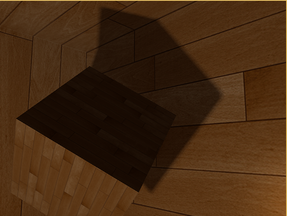
The result is a gray-scale scene, where each color represents the linear depth of the scene:
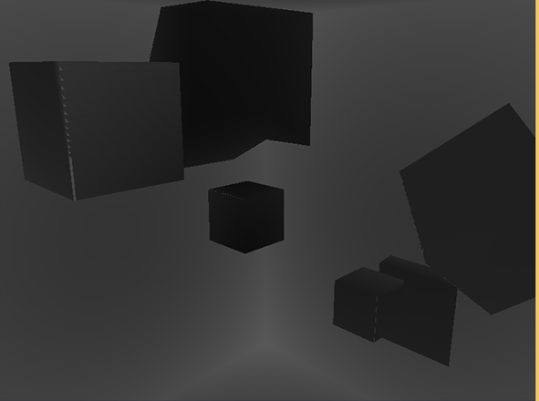
You may also notice that the shaded part is outside the wall. If it looks like this, you know that the depth cube map is generated correctly. Otherwise, you might have done something wrong. Maybe closestDepth is still in the range of 0 to far_plane.
Since point shadow mapping is based on the principle of traditional Shadow Mapping, it also inherits the non-reality generated by resolution. If you zoom in, you'll see the serrated edges. PCF, or Percentage-close filtering, allows us to filter multiple samples around fragment locations and average the results.
If we use the same simple PCF filter as the previous tutorial and add a third dimension, that's it:
float shadow = 0.0;
float bias = 0.05;
float samples = 4.0;
float offset = 0.1;
for(float x = -offset; x < offset; x += offset / (samples * 0.5))
{
    for(float y = -offset; y < offset; y += offset / (samples * 0.5))
    {
        for(float z = -offset; z < offset; z += offset / (samples * 0.5))
        {
            float closestDepth = texture(depthMap, fragToLight + vec3(x, y, z)).r;
            closestDepth *= far_plane;   // Undo mapping [0;1]
            if(currentDepth - bias > closestDepth)
                shadow += 1.0;
        }
    }
}
shadow /= (samples * samples * samples);
This code is not much different from our traditional Shadow Mapping. Here we calculate the texture offset dynamically according to the number of samples. We sampled three times in three axes, and eventually averaging the sub-samples.
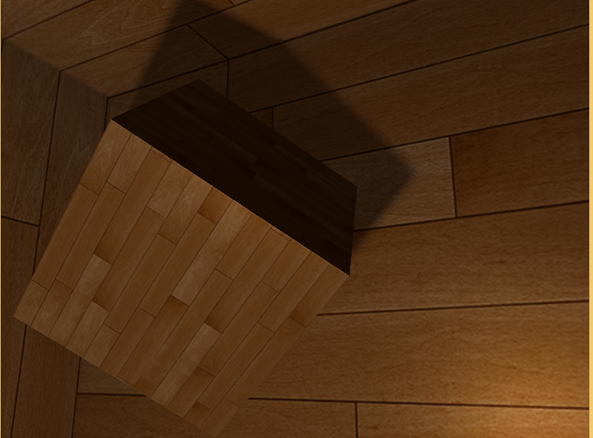
Now the shadows look softer and smoother, giving a more realistic effect:
However, samples is set to 4.0, and we get a total of 64 samples per fragment. That's too much! ___________
Most of these samples are redundant. It is more meaningful to sample near the original direction vector than in the vertical direction of the sampling direction vector. However, there is no (simple) way to point out which sub-direction is redundant, which is difficult. A trick to use is to use an array of offset directions, which are almost separated, each pointing in a completely different direction, eliminating those sub-directions that are close to each other. Here's an array with 20 migration directions:
vec3 sampleOffsetDirections[20] = vec3[]
(
   vec3( 1,  1,  1), vec3( 1, -1,  1), vec3(-1, -1,  1), vec3(-1,  1,  1),
   vec3( 1,  1, -1), vec3( 1, -1, -1), vec3(-1, -1, -1), vec3(-1,  1, -1),
   vec3( 1,  1,  0), vec3( 1, -1,  0), vec3(-1, -1,  0), vec3(-1,  1,  0),
   vec3( 1,  0,  1), vec3(-1,  0,  1), vec3( 1,  0, -1), vec3(-1,  0, -1),
   vec3( 0,  1,  1), vec3( 0, -1,  1), vec3( 0, -1, -1), vec3( 0,  1, -1)
);
Then we adapted the PCF algorithm to the number of samples obtained from sampleOffset Directions and used them to sample from cube maps. The advantage of doing this is that we need fewer samples than previous PCF algorithms.
float shadow = 0.0;
float bias = 0.15;
int samples = 20;
float viewDistance = length(viewPos - fragPos);
float diskRadius = 0.05;
for(int i = 0; i < samples; ++i)
{
    float closestDepth = texture(depthMap, fragToLight + sampleOffsetDirections[i] * diskRadius).r;
    closestDepth *= far_plane;   // Undo mapping [0;1]
    if(currentDepth - bias > closestDepth)
        shadow += 1.0;
}
shadow /= float(samples);
Here we add an offset to the specified disk Radius, which samples from the cube map around the fragTo Light direction vector.
Another interesting technique that can be applied here is that we can change diskRadius based on the distance of a fragment in the observer; so that we can increase the offset radius according to the distance of the observer, and the shadows are softer and sharper when the distance is farther.
float diskRadius = (1.0 + (viewDistance / far_plane)) / 25.0;
If the result of PCF algorithm is not better, it is also very good, which is a soft shadow effect:
Remind me that using geometric shaders to generate depth maps is not necessarily faster than rendering the scene six times per face. Geometric shader has its own performance limitations, and it may achieve better performance in the first stage. It depends on the type of environment, specific graphics driver, etc., so if you are concerned about performance, make sure you have a general understanding of both approaches and choose the one that is more efficient for your scenario.