In the learning part of attitude control, multi rotor attitude control is taken as an example.
1. Overall process
Attitude control is mainly divided into several parts:
Attitude error angle calculation = > target angular velocity calculation = > angular velocity PID
This part focuses on the calculation of attitude error angle.
2. Calculation of attitude error angle
The purpose of attitude error calculation is to know how many angles the UAV can rotate from this state to the target state. Literally, isn't the attitude error angle the difference between the current attitude and the target attitude (as follows)?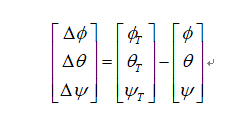
And that's what a lot of flight controllers do (anonymity, fire and so on)
So what's wrong with that?
First of all, you can refer to the last section, how does the attitude of UAV come from? It comes from the inverse trigonometric function of the attitude rotation matrix, which is based on the definition of coordinate system. For example, the definition of European and American coordinate system is different from that of Soviet and Russian coordinate system. The attitude of XYZ axis is different, and the rotation order is also different. For the same three attitude angles, the calculated attitude matrix is also different.
It seems to be a bit far away. In fact, I want to say that the attitude is based on the definition of rotation, so the attitude error should also be based on the definition of rotation. Although the definition of attitude error in some flight control meets the above formula, it is based on the assumption of small angle, not the real attitude error. Therefore, the attitude error calculation method in Pixhawk is based on the rotation matrix of attitude error angle.
Return to the right.
The calculation of attitude error angle in Pixhawk involves three coordinate systems. Body coordinate system b, geographical coordinate system n and heading drift coordinate system r. Firstly, according to the current attitude and the expected attitude, the attitude rotation matrix of the two states is given by the quaternion of the two states
	/* construct attitude setpoint rotation matrix */
	math::Quaternion q_sp(_v_att_sp.q_d[0], _v_att_sp.q_d[1], _v_att_sp.q_d[2], _v_att_sp.q_d[3]);
	math::Matrix<3, 3> R_sp = q_sp.to_dcm();

	/* get current rotation matrix from control state quaternions */
	math::Quaternion q_att(_ctrl_state.q[0], _ctrl_state.q[1], _ctrl_state.q[2], _ctrl_state.q[3]);
	math::Matrix<3, 3> R = q_att.to_dcm();
Where R ﹣ SP is the target attitude matrix, which is given by the velocity position loop; R is the current attitude matrix. In Pixhawk, the method of first calculating the Z-axis (i.e. calculating the horizontal two speeds) and then compensating the heading angle is adopted. Therefore, first, two vectors representing the Z-axis vector are taken out:
	/* try to move thrust vector shortest way, because yaw response is slower than roll/pitch */
	math::Vector<3> R_z(R(0, 2), R(1, 2), R(2, 2));
	math::Vector<3> R_sp_z(R_sp(0, 2), R_sp(1, 2), R_sp(2, 2));
Then, the cross product is used to obtain the rotation vector (leading to the machine system) needed for the two vectors to be coaxial
	/* axis and sin(angle) of desired rotation */
	math::Vector<3> e_R = R.transposed() * (R_z % R_sp_z);
Then calculate the angle that needs to rotate around the vector and unit the vector, and then decompose the angle to two horizontal angles:
/* calculate angle error */
	float e_R_z_sin = e_R.length();
	float e_R_z_cos = R_z * R_sp_z;
	float e_R_z_angle = atan2f(e_R_z_sin, e_R_z_cos);
		math::Vector<3> e_R_z_axis = e_R / e_R_z_sin;

		e_R = e_R_z_axis * e_R_z_angle;
The first term and the second term of the above-mentioned e? R are the two horizontal attitude errors.
Then calculate the heading and attitude error angle. The attitude matrix of R (course not aligned) is defined as R ﹐ RP. The attitude matrix is obtained from the R matrix by rotating the e ﹣ r vector. At present, the vector of the vector and the angle of rotation around the vector are known, and R ﹐ RP can be obtained according to Rodrigo's rotation formula. See details:
Calculating rotation matrix according to the vector value before and after rotation
Therefore, the heading angle error can be obtained from R ﹣ RP and R ﹣ sp
math::Matrix<3, 3> e_R_cp;
		e_R_cp.zero();
		e_R_cp(0, 1) = -e_R_z_axis(2);
		e_R_cp(0, 2) = e_R_z_axis(1);
		e_R_cp(1, 0) = e_R_z_axis(2);
		e_R_cp(1, 2) = -e_R_z_axis(0);
		e_R_cp(2, 0) = -e_R_z_axis(1);
		e_R_cp(2, 1) = e_R_z_axis(0);

		/* rotation matrix for roll/pitch only rotation */
		R_rp = R * (_I + e_R_cp * e_R_z_sin + e_R_cp * e_R_cp * (1.0f - e_R_z_cos));
Yaw? Is a attenuation coefficient, whose purpose is to rotate the roll and pitch angle first.
/* calculate weight for yaw control */
	float yaw_w = R_sp(2, 2) * R_sp(2, 2);
So far, three attitude error angles have been obtained.
In Pixhawk code, there is also an algorithm that uses quaternion to calculate attitude angle error. It is explained that when the two Z axes are 90 degrees, because of the problem of cos singularity, quaternion is directly used to solve the problem. (there is a question, why can't we use quaternion directly???)
/* for large thrust vector rotations use another rotation method:
		 * calculate angle and axis for R -> R_sp rotation directly */
		math::Quaternion q_error;
		q_error.from_dcm(R.transposed() * R_sp);
		math::Vector<3> e_R_d = q_error(0) >= 0.0f ? q_error.imag()  * 2.0f : -q_error.imag() * 2.0f;

		/* use fusion of Z axis based rotation and direct rotation */
		float direct_w = e_R_z_cos * e_R_z_cos * yaw_w;
		e_R = e_R * (1.0f - direct_w) + e_R_d * direct_w;
3. Calculation of target angular velocity
In the attitude control, the calculation from angle control loop to angular velocity control loop is relatively simple. The target angular velocity can be obtained by directly proportional calculation of attitude angle error
	/* calculate angular rates setpoint */
	_rates_sp = _params.att_p.emult(e_R);
4. Angular speed loop control
The angular velocity loop control is more regular, that is, PID control.
	_att_control = _params.rate_p.emult(rates_err * tpa) + _params.rate_d.emult(_rates_prev - rates) / dt + _rates_int +
		       _params.rate_ff.emult(_rates_sp);
In particular, for PID integral terms, there are several anti integral saturation operations.
The aircraft needs to leave the ground to start integration;
The calculated motor command value is within the limit;
The calculated value of angular velocity change is less than the value of overall thrust setting.
	/* update integral only if not saturated on low limit and if motor commands are not saturated */
	if (_thrust_sp > MIN_TAKEOFF_THRUST && !_motor_limits.lower_limit && !_motor_limits.upper_limit) {
		for (int i = AXIS_INDEX_ROLL; i < AXIS_COUNT; i++) {
			if (fabsf(_att_control(i)) < _thrust_sp) {
				float rate_i = _rates_int(i) + _params.rate_i(i) * rates_err(i) * dt;

				if (PX4_ISFINITE(rate_i) && rate_i > -RATES_I_LIMIT && rate_i < RATES_I_LIMIT &&
				    _att_control(i) > -RATES_I_LIMIT && _att_control(i) < RATES_I_LIMIT &&
				    /* if the axis is the yaw axis, do not update the integral if the limit is hit */
				    !((i == AXIS_INDEX_YAW) && _motor_limits.yaw)) {
					_rates_int(i) = rate_i;
				}
			}
		}
	}

