Catalogue of series articles
Detailed explanation of Linux character device driver
Detailed explanation of Linux character device driver II (using device driver model)
Detailed explanation of Linux character device driver III (using class)
Detailed explanation of Linux character device driver IV (using its own xbus driver bus)
Detailed explanation of Linux character device driver V (using platform virtual platform bus)
Detailed explanation of Linux character device driver VI (RGB lamp driver realized by device tree)
Detailed explanation of Linux character device driver VII ("plug in" device tree realizes RGB lamp driver)
preface
Through the previous seven articles, we learned that when controlling a hardware peripheral, we need to obtain the GPIO used by the peripheral, then query the relevant registers in the chip manual, and then control the corresponding peripheral through the control register. Using the method of directly operating the register to write the driver, it is obvious that this development method is inefficient and write programs It is also very troublesome, so the pinctrl subsystem is introduced to solve this problem.
text
introduce
As we all know, ARM SoC provides very rich hardware interfaces, and the physical performance of the interface is one pin (or pad, finger, etc.) In order to realize rich hardware functions, SOC pins need to realize multiplexing functions, that is, separate pins need to provide different functions. For example, pin0 can be used as GPIO or SCL of i2c. Different functions can be switched through pin related multiplexing registers. In addition, the software can also configure pin related electrical characteristics through registers, such as pull-up / pull-down and drive Capacity, leakage opening, etc.
In the kernel before Linux kernel 3.0, the function configuration of the pin is initialized through the configuration file of the target board (arch/arm/mach - *). This configuration method is cumbersome and prone to problems (for example, the function configuration of the pin conflicts) Therefore, after Linux kernel 3.0, the board level configuration information management mechanism of DT is implemented, which greatly improves the configuration mode of pin. Along with it, the pinctrl subsystem is implemented.
The pinctrl subsystem is mainly responsible for the following functions:
1. Enumerate and name all pin s configured through board level DTS;
2. Realize multiplexing function for pin;
3. Configure the electrical characteristics of the pin, such as pull-up / pull-down, driving capacity, open drain, etc.
It is further understood that no matter what kind of chip, it has a structure similar to the following figure:
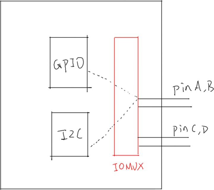
To use pinA and B for GPIO, you need to set IOMUX to connect them to GPIO module. To use pinA and B for I2C, you need to set IOMUX to connect them to I2C module.
Therefore, GPIO and I2C should be in parallel relationship. Before they can be used, IOMUX needs to be set. Sometimes it is not only to set IOMUX, but also to configure pins, such as pull-up, pull-down, open drain, etc.
Nowadays, chips often have hundreds of pins. When using the GPIO function, it is obviously impossible for you to find the corresponding registers one pin at a time. If the technology industry has expertise, these laborious tasks let the BSP engineers of chip manufacturers. As drive engineers, they need to develop on their basis.
Therefore, the pin reuse and configuration should be extracted and made into Pinctrl subsystem for GPIO, I2C and other modules. What should BSP engineers do? As shown in the figure below:
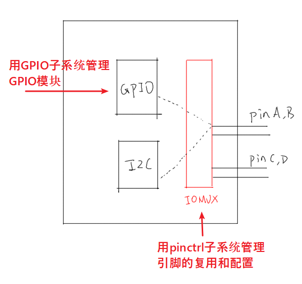
After BSP engineers add their own chip support in GPIO subsystem and Pinctrl subsystem, we can use these pins very conveniently.
In the figure, the GPIO modules are juxtaposed with I2C. Why are the GPIO subsystems involved when talking about Pinctrl? Most chips do not have separate IOMUX modules. Pin multiplexing and configuration are implemented inside the GPIO module. In hardware, GPIO and Pinctrl are so closely related, and in software, they are also very closely related. Therefore, these two subsystems are generally the same Start explaining.
As for the relationship between these two subsystems, these two subsystems are the concepts above the software and part of the Linux kernel. However, they should be linked to the actual hardware in the end. For specific understanding, please refer to the following figure:
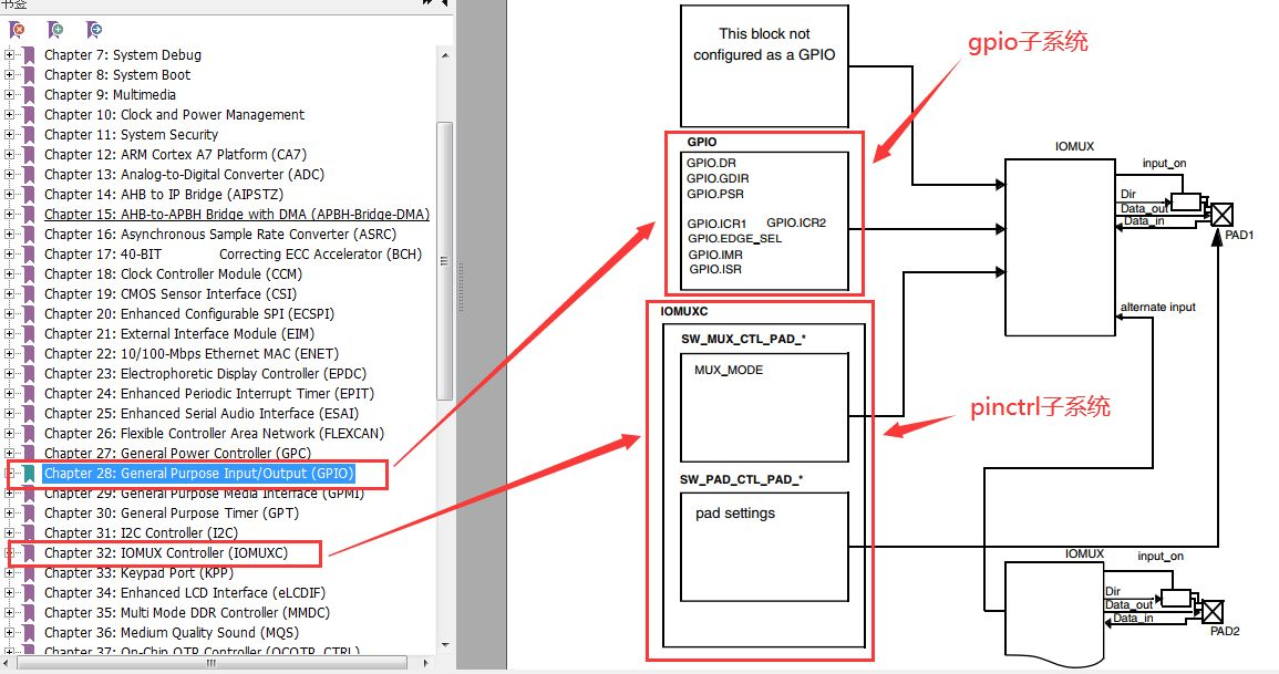
To manipulate a pin, we need to configure registers of two modules: GPIO module and IOMUXC module. IOMUXC module is used to configure pin functions and some pin parameters (pin rate, up and down, etc.); GPIO module is used to configure pin input and output, etc. among them, pinctrl subsystem manages IOMUXC module; GPIO subsystem manages GPIO module.
To sum up, in the development of embedded Linux, the led driving methods (dealing with registers) mentioned in the previous notes are basically useless. The Linux kernel provides pinctrl and gpio subsystems for pin driving, so that we can avoid dealing with registers.
iomuxc node: pinctrl subsystem
- Summarize the configuration information of the required pins
- The pinctrl subsystem stores iomux node information in advance
iomuxc node
imx6ull.dtsi
iomuxc: iomuxc@20e0000 {
				compatible = "fsl,imx6ul-iomuxc";
				reg = <0x20e0000 0x4000>;
			};
- compatible: match with the platform driver of the pinctrl subsystem
- reg: base address of pin configuration register
imx6ull-seeed-npi.dts
&iomuxc {
	pinctrl-names = "default","init","sleep";
	pinctrl-0 = <&pinctrl_hog_1>;
	pinctrl-1 =<&xxx>;
	pinctrl-2 =<&yyy>;
...
	pinctrl_uart1: uart1grp {
		fsl,pins = <
			MX6UL_PAD_UART1_TX_DATA__UART1_DCE_TX 0x1b0b1
			MX6UL_PAD_UART1_RX_DATA__UART1_DCE_RX 0x1b0b1
		>;
	};
...
}
Node pin configuration mode
- Pinctrl names: defines the pin status
- pinctrl-0: defines the pin to be used in the 0th state. Other node IDs can be referenced
- pinctrl-1: define the pins to be used in the first state, and so on
- ...
Node configuration information record
fsl,pins
- Combined with pinctrl subsystem driver of imx6ull
- This attribute is used to identify the configuration information of the pin
FSL, pin attribute value
One macro + one hexadecimal number
MX6UL_PAD_UART1_TX_DATA__UART1_DCE_TX 0x1b0b1
Macro definition prototype
imx6ull.dtsi ->#include "imx6ull-pinfunc.h"->#include "imx6ul-pinfunc.h"
#define MX6UL_PAD_UART1_TX_DATA__UART1_DCE_TX 0x0084 0x0310 0x0000 0 0
Macro value meaning
<mux_reg conf_reg input_reg mux_mode input_val>
 0x0084    0x0310    0x0000     0x0      0x0
mux_reg: pin multiplexing setting register
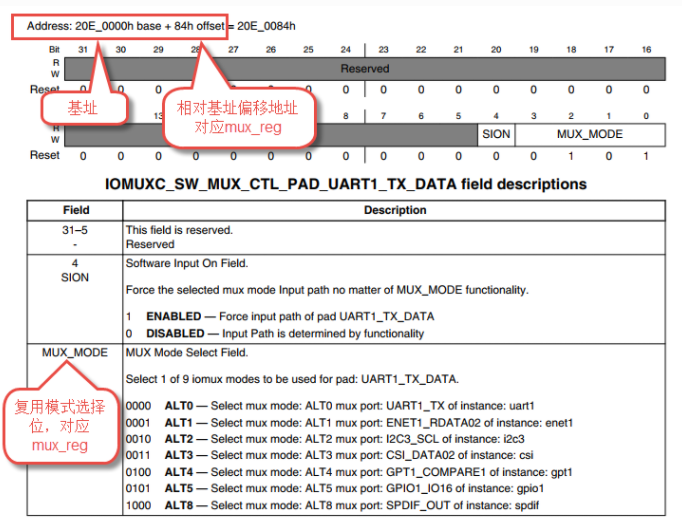
conf_reg: pin attribute setting register
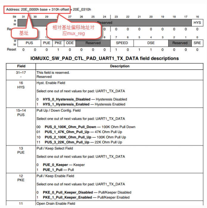 input_reg: pin input setting register

- Set when the pin requires an input function
- mux_mode: multiplex register setting value
- Set pin reuse
- input_value: input register setting value
- Set pin input characteristics
Hexadecimal number
Property register setting value
- Complex characteristics and independent settings
pinctrl subsystem experiment: RGB lamp pin initialization
platform device pin initialization
Register platform device or platform driver
RGB lamp pin status initialization
Compared with the previous two articles, that is, comparing the device tree and plug-in device tree, the traditional device tree imx6ull-speed-npi.dts file has the following two parts through the lighting of pinctrl subsystem
Add pin configuration information to iomuxc node
pinctrl_rgb_led:rgb_led{
                    fsl,pins = <
                            MX6UL_PAD_GPIO1_IO04__GPIO1_IO04    0x000010B1
                            MX6UL_PAD_CSI_HSYNC__GPIO4_IO20     0x000010B1
                            MX6UL_PAD_CSI_VSYNC__GPIO4_IO19     0x000010B1
                    >;
            };
rgb_led node add pin status
pinctrl-names = "default";
 pinctrl-0 = <&pinctrl_rgb_led>;
Code example
Take the wildfire code as an example
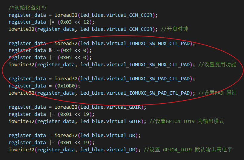
The codes related to pin configuration initialization are deleted from the dts_led.c file as follows (in fact, only the codes in the red box can be deleted, and all deletion has no impact on the test in this paper). The reason for deletion is that we helped us complete some of the initialization work through the iomuxc node and pinctrl subsystem mechanism.
dts_led.c
#include <linux/init.h>
#include <linux/module.h>
#include <linux/fs.h>
#include <linux/cdev.h>
#include <linux/uaccess.h>
#include <linux/string.h>
#include <linux/types.h>
#include <linux/kernel.h>
#include <linux/delay.h>
#include <linux/ide.h>
#include <linux/errno.h>
#include <linux/gpio.h>
#include <asm/mach/map.h>
#include <linux/of.h>
#include <linux/of_address.h>
#include <linux/of_gpio.h>
#include <asm/io.h>
#include <linux/device.h>

#include <linux/platform_device.h>

/*------------------Character device content----------------------*/
#define DEV_NAME "rgb_led"
#define DEV_CNT (1)

/*Define the led resource structure and save the obtained node information and the converted virtual register address*/
struct led_resource
{
	struct device_node *device_node; //Device tree node of rgb_led_red
	void __iomem *virtual_CCM_CCGR;
	void __iomem *virtual_IOMUXC_SW_MUX_CTL_PAD;
	void __iomem *virtual_IOMUXC_SW_PAD_CTL_PAD;
	void __iomem *virtual_DR;
	void __iomem *virtual_GDIR;
};

static dev_t led_devno;					 //Defines the device number of the character device
static struct cdev led_chr_dev;			 //Define character device structure chr_dev
struct class *class_led;				 //Save the created class
struct device *device;					 // Save the created device
struct device_node *rgb_led_device_node; //rgb_led device tree node structure

/*Define the LEDs of the three lamps R, G and B_ The resource structure holds the obtained node information*/
struct led_resource led_red;
struct led_resource led_green;
struct led_resource led_blue;

/*Character device operation function set, open function*/
static int led_chr_dev_open(struct inode *inode, struct file *filp)
{
	printk("\n open form driver \n");
	return 0;
}

/*Character device operation function set, write function*/
static ssize_t led_chr_dev_write(struct file *filp, const char __user *buf, size_t cnt, loff_t *offt)
{

	int ret,error;
	unsigned int register_data = 0; //Temporarily store the read register data
	unsigned char receive_data[10]; //Used to save received data
	unsigned int write_data; //Used to save received data

	if(cnt>10)
			cnt =10;

	error = copy_from_user(receive_data, buf, cnt);
	if (error < 0)
	{
		return -1;
	}

	ret = kstrtoint(receive_data, 16, &write_data);
	if (ret) {
		return -1;
        }

	/*Set GPIO1_04 output level*/
	if (write_data & 0x04)
	{
		register_data = ioread32(led_red.virtual_DR);
		register_data &= ~(0x01 << 4);
		iowrite32(register_data, led_red.virtual_DR); // GPIO1_ Pin 04 outputs low level, and the red light is on
	}
	else
	{
		register_data = ioread32(led_red.virtual_DR);
		register_data |= (0x01 << 4);
		iowrite32(register_data, led_red.virtual_DR); // GPIO1_ Pin 04 outputs high level, and the red light goes out
	}

	/*Set GPIO4_20 output level*/
	if (write_data & 0x02)
	{
		register_data = ioread32(led_green.virtual_DR);
		register_data &= ~(0x01 << 20);
		iowrite32(register_data, led_green.virtual_DR); // GPIO4_20 pin output low level, green light on
	}
	else
	{
		register_data = ioread32(led_green.virtual_DR);
		register_data |= (0x01 << 20);
		iowrite32(register_data, led_green.virtual_DR); // GPIO4_20 pin output high level, green light off
	}

	/*Set GPIO4_19 output level*/
	if (write_data & 0x01)
	{
		register_data = ioread32(led_blue.virtual_DR);
		register_data &= ~(0x01 << 19);
		iowrite32(register_data, led_blue.virtual_DR); //GPIO4_ Pin 19 output low level, blue light on
	}
	else
	{
		register_data = ioread32(led_blue.virtual_DR);
		register_data |= (0x01 << 19);
		iowrite32(register_data, led_blue.virtual_DR); //GPIO4_ Pin 19 output high level, blue light off
	}

	return cnt;
}

/*Character device operation function set*/
static struct file_operations led_chr_dev_fops =
	{
		.owner = THIS_MODULE,
		.open = led_chr_dev_open,
		.write = led_chr_dev_write,
};

/*----------------Platform driven function set-----------------*/
static int led_probe(struct platform_device *pdv)
{

	int ret = -1; //Save error status code
	unsigned int register_data = 0;

	printk(KERN_ALERT "\t  match successed  \n");

	/*Get rgb_led device tree node*/
	rgb_led_device_node = of_find_node_by_path("/rgb_led");
	if (rgb_led_device_node == NULL)
	{
		printk(KERN_ERR "\t  get rgb_led failed!  \n");
		return -1;
	}

	/*Get RGB_ Red light child node of LED node*/
	led_red.device_node = of_find_node_by_name(rgb_led_device_node,"rgb_led_red");
	if (led_red.device_node == NULL)
	{
		printk(KERN_ERR "\n get rgb_led_red_device_node failed ! \n");
		return -1;
	}


	/*Get reg attribute and convert to virtual address*/
	led_red.virtual_CCM_CCGR = of_iomap(led_red.device_node, 0);
	led_red.virtual_IOMUXC_SW_MUX_CTL_PAD = of_iomap(led_red.device_node, 1);
	led_red.virtual_IOMUXC_SW_PAD_CTL_PAD = of_iomap(led_red.device_node, 2);
	led_red.virtual_DR = of_iomap(led_red.device_node, 3);
	led_red.virtual_GDIR = of_iomap(led_red.device_node, 4);


	/*Get RGB_ Green sub node of LED node*/
	led_green.device_node = of_find_node_by_name(rgb_led_device_node,"rgb_led_green");
	if (led_green.device_node == NULL)
	{
		printk(KERN_ERR "\n get rgb_led_green_device_node failed ! \n");
		return -1;
	}

	/*Get reg attribute and convert to virtual address*/
	led_green.virtual_CCM_CCGR = of_iomap(led_green.device_node, 0);
	led_green.virtual_IOMUXC_SW_MUX_CTL_PAD = of_iomap(led_green.device_node, 1);
	led_green.virtual_IOMUXC_SW_PAD_CTL_PAD = of_iomap(led_green.device_node, 2);
	led_green.virtual_DR = of_iomap(led_green.device_node, 3);
	led_green.virtual_GDIR = of_iomap(led_green.device_node, 4);


	/*Get RGB_ Blue light child node of LED node*/
	led_blue.device_node = of_find_node_by_name(rgb_led_device_node,"rgb_led_blue");
	if (led_blue.device_node == NULL)
	{
		printk(KERN_ERR "\n get rgb_led_blue_device_node failed ! \n");
		return -1;
	}

	/*Get reg attribute and convert to virtual address*/
	led_blue.virtual_CCM_CCGR = of_iomap(led_blue.device_node, 0);
	led_blue.virtual_IOMUXC_SW_MUX_CTL_PAD = of_iomap(led_blue.device_node, 1);
	led_blue.virtual_IOMUXC_SW_PAD_CTL_PAD = of_iomap(led_blue.device_node, 2);
	led_blue.virtual_DR = of_iomap(led_blue.device_node, 3);
	led_blue.virtual_GDIR = of_iomap(led_blue.device_node, 4);


	/*---------------------Register character device section-----------------*/

	//First step
	//The equipment number is obtained by dynamic allocation, and the secondary equipment number is 0,
	//The device name is RGB LEDs, which can be viewed through the command cat / proc / devices
	//DEV_CNT is 1. Currently, only one equipment number is applied
	ret = alloc_chrdev_region(&led_devno, 0, DEV_CNT, DEV_NAME);
	if (ret < 0)
	{
		printk("fail to alloc led_devno\n");
		goto alloc_err;
	}
	//Step 2
	//Associated character device structure cdev and file operation structure file_operations
	led_chr_dev.owner = THIS_MODULE;
	cdev_init(&led_chr_dev, &led_chr_dev_fops);
	//Step 3
	//Add device to cdev_map hash table
	ret = cdev_add(&led_chr_dev, led_devno, DEV_CNT);
	if (ret < 0)
	{
		printk("fail to add cdev\n");
		goto add_err;
	}

	//Step 4
	/*Create class */
	class_led = class_create(THIS_MODULE, DEV_NAME);

	/*Create device*/
	device = device_create(class_led, NULL, led_devno, NULL, DEV_NAME);

	return 0;

add_err:
	//When adding a device fails, you need to log off the device number
	unregister_chrdev_region(led_devno, DEV_CNT);
	printk("\n error! \n");
alloc_err:

	return -1;
}

static const struct of_device_id rgb_led[] = {
	{.compatible = "fire,rgb_led"},
	{/* sentinel */}};

/*Define platform equipment structure*/
struct platform_driver led_platform_driver = {
	.probe = led_probe,
	.driver = {
		.name = "rgb-leds-platform",
		.owner = THIS_MODULE,
		.of_match_table = rgb_led,
	}};

/*
*Driver initialization function
*/
static int __init led_platform_driver_init(void)
{
	int DriverState;
	DriverState = platform_driver_register(&led_platform_driver);
	printk(KERN_ALERT "\tDriverState is %d\n", DriverState);
	return 0;
}

/*
*Drive logoff function
*/
static void __exit led_platform_driver_exit(void)
{
	/*Unmap physical address to virtual address*/
	iounmap(led_green.virtual_CCM_CCGR);
	iounmap(led_green.virtual_IOMUXC_SW_MUX_CTL_PAD);
	iounmap(led_green.virtual_IOMUXC_SW_PAD_CTL_PAD);
	iounmap(led_green.virtual_DR);
	iounmap(led_green.virtual_GDIR);

	iounmap(led_red.virtual_CCM_CCGR);
	iounmap(led_red.virtual_IOMUXC_SW_MUX_CTL_PAD);
	iounmap(led_red.virtual_IOMUXC_SW_PAD_CTL_PAD);
	iounmap(led_red.virtual_DR);
	iounmap(led_red.virtual_GDIR);

	iounmap(led_blue.virtual_CCM_CCGR);
	iounmap(led_blue.virtual_IOMUXC_SW_MUX_CTL_PAD);
	iounmap(led_blue.virtual_IOMUXC_SW_PAD_CTL_PAD);
	iounmap(led_blue.virtual_DR);
	iounmap(led_blue.virtual_GDIR);

	/*Delete device*/
	device_destroy(class_led, led_devno);		  //Clear device
	class_destroy(class_led);					  //Clear class
	cdev_del(&led_chr_dev);						  //Clear device number
	unregister_chrdev_region(led_devno, DEV_CNT); //Unregister character device

	/*Unregister character device*/
	platform_driver_unregister(&led_platform_driver);

	printk(KERN_ALERT "led_platform_driver exit!\n");
}

module_init(led_platform_driver_init);
module_exit(led_platform_driver_exit);

MODULE_LICENSE("GPL");

/**/
summary
Similarly, compile the traditional device tree imx6ull-speed-npi.dts into the rgb.dtbo plug-in device tree and load it into the kernel. After loading, use the following command to view the device tree. At this time, you can see the new RGB in the number of devices_ Led node.
ls /sys/firmware/devicetree/base
 perhaps
ls /proc/device-tree
Recompile DTS_ The LED. C source file is dto.led.ko kernel module and loaded into the kernel. Then there is / dev/rgb_led node, and finally to / dev/rgb_led node can control rgb lamp by writing data.
sudo sh -c "ecoh '1' >/dev/rgb_led"
Bright blue light
sudo sh -c "ecoh '2' >/dev/rgb_led"
Green light
sudo sh -c "ecoh '4' >/dev/rgb_led"
on shaky ground
sudo sh -c "ecoh '7' >/dev/rgb_led"
Full bright
reference resources:
[depth] use of GPIO and Pinctrl subsystems - Weidong mountain
[Linux notes] Pinctrl subsystem and GPIO subsystem – embedded hodgepodge
pinctrl subsystem of Linux kernel
L2.Pinctrl subsystem