sometimes embedded systems also need to display more complex graphics and richer data display. To this end, we need a larger, richer color display screen with touch screen. Of course, it's best to have a higher cost performance. When we encounter such needs in our projects, we sometimes choose DWIN touch screen. In this article, we will design and implement the driver of DWIN touch screen.
1. Function overview
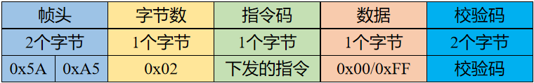
what we are talking about here is Devon's serial port screen, which has a variety of interface types, including screen using RS485 interface and screen that can realize TTL interface or RS232 interface through jumper. However, the same communication protocol shall be adopted for any interface. The complete instruction structure of the communication protocol adopted by Devon serial port screen is shown in the figure below:

the CRC check does not include the frame header and data length, and only checks the instructions and data. CRC verification adopts ANSI CRC-16 (X16+X15+X2+1) format. When CRC frame verification is enabled and automatic response function is enabled (R2.4=1, RC.3=1), DGUS screen will automatically respond to the verification after CRC verification is completed, and the return command structure is as follows:
Frame header + 02 + (* * * * DGUS screen received) instruction + data (* * * * 0xFF indicates CRC verification is correct, * * * * 0x00 indicates CRC verification error) + CRC.
Devin's DGUS decomposes each page of the user graphical interface into multiple control variables, that is, the DGUS screen works in variable driven mode, and the working mode of the screen and the state of the GUI are completely controlled by data variables. Therefore, serial instructions only need to read and write variables. The instruction set is very simple, with only 5 instructions in total. The read-write instruction set is shown in the following figure:

the configuration register space is used to store instruction States, such as RTC (real-time time), backlight brightness and other real-time states. Knowing the address of the register and the function of each register can realize the information transmission and control between the host computer and DGUS screen through serial port instructions. The register address is 0x00~0xFF. See the function description of Devon register for specific functions.
2. Driver design and Implementation
having understood the communication protocol of Devon screen, we can write the driver of Devon screen based on it. We know that the communication protocol of Devon screen has five instructions, and our driver operates Devon screen through these five instructions.
2.1 object definition
we still use the object-based operation method, so first we still define the object type of Devon screen. The specific definitions are as follows:
/* Define the object type of Devon serial port screen */
typedef struct DwinObject {

     DwinCheckCodeType checkMode;       //Verification method
     void (*SendData)(uint8_t *txData,uint16_t length);   //send data
     void (*GetRegister)(struct DwinObject *dwin,uint8_t regAddress,uint8_t readByteLength);
     void (*SetRegister)(struct DwinObject *dwin,uint8_t regAddress,uint8_t *txData,uint16_t length);
}DwinObjectType;
we did not abstract too many attributes from the Devon screen object type, because the screen, as a slave device, did not return too much information and did not have any selection features. Considering that the verification of communication information can be enabled or not, we abstract it as an attribute to distinguish it from different situations.
objects also need to be initialized before they are used, so we need object initialization functions. The initialization function is as follows:
/* Initialize Devon serial port screen object */
void DwinInitialization(DwinObjectType *dwin,DwinCheckCodeType checkMode,SendDataForDwinType SendData)
{
     if((dwin==NULL)||(SendData==NULL))
     {
        return;
     }

     dwin->checkMode=checkMode;
     dwin->SendData=SendData;

     dwin->GetRegister=GetRegisterDataFromDwinLCD;
     dwin->SetRegister=SetRegisterDataToDwinLCD;
}
2.2 object operation
you can operate on the defined and initialized objects. As we have said, the Devon screen communication protocol has five operation codes. They are: 0x80, write register; 0x81, read register; 0x82, write data memory; 0x83, read data memory; 0x84, write curve buffer. Our operation on the screen is to use these five operation codes.
2.2.1 write register
write data to the specified register address, and the instruction code is 0x80. This command supports the continuous write operation of multiple registers, but can only write 16 bytes of data at most. We write the operation function according to the format of the message frame mentioned above as follows:
/*When writing register data, it is allowed to write up to 16 bytes at a time, that is, length < = 16*/
static void SetRegisterDataToDwinLCD(DwinObjectType *dwin,uint8_t regAddress,uint8_t *txData,uint16_t length)
{
 /*The length of command consists of frame header (2 bytes) + data length (1 byte) + instruction (1 byte) + register address (1 byte) + written data (up to 16 bytes) + CRC check (2 bytes)*/
 uint16_t cmd_Length=length+5;
 uint8_t cmd_Reg_Write[23];
 cmd_Reg_Write[0]=0x5A;
 cmd_Reg_Write[1]=0xA5;
 cmd_Reg_Write[2]=(uint8_t)(length+2);
 cmd_Reg_Write[3]= FC_REG_Write;
 cmd_Reg_Write[4]=regAddress;
 for(int dataIndex=0;dataIndex<length;dataIndex++)
 {
  cmd_Reg_Write[dataIndex+5]=txData[dataIndex];
 }

     if(dwin->checkMode>DwinNone)
     {
        uint16_t checkCode=CalcDwinCRC16(&cmd_Reg_Write[3],length+2);
        cmd_Reg_Write[length+5]=(uint8_t)checkCode;
        cmd_Reg_Write[length+6]=(uint8_t)(checkCode>>8);
        cmd_Length=cmd_Length+2;
     }

 dwin->SendData(cmd_Reg_Write,cmd_Length);
}
2.2.2 read register
read the data of the specified byte length from the specified register address, and the instruction code is 0x81. Read one or more registers at a time. Since the register address is 0x00 to 0xFF, theoretically all registers can be read at one time. We can write the operation function according to the message format as follows:
/*Read register data*/
static void GetRegisterDataFromDwinLCD(DwinObjectType *dwin,uint8_t regAddress,uint8_t readByteLength)
{
 /*The length of command consists of frame header (2 bytes) + data length (1 byte) + instruction (1 byte) + register address (1 byte) + byte length of read register (1 byte) + CRC check (2 bytes)*/
 uint16_t cmd_Length=6;
 uint8_t cmd_Reg_Read[]={0x5A,0xA5,0x03,FC_REG_Read,0x00,0x00,0x00,0x00};//Read data command
 cmd_Reg_Read[4]=regAddress;
 cmd_Reg_Read[5]=readByteLength;

     if(dwin->checkMode>DwinNone)
     {
        uint16_t checkCode=CalcDwinCRC16(&cmd_Reg_Read[3],3);
        cmd_Reg_Read[6]=(uint8_t)checkCode;
        cmd_Reg_Read[7]=(uint8_t)(checkCode>>8);
        cmd_Length=cmd_Length+2;
     }

 dwin->SendData(cmd_Reg_Read,cmd_Length);
}
2.2.3 write memory
write the data string (word data) to the variable storage area from the specified variable memory address, and the instruction code is 0x82. The storage area is different from the register. The address and data are 16 bits. In theory, you can write almost 100 words of data at a time. In fact, this extreme method is usually not recommended. So we limit the length to 100 bytes. We can write the operation function according to the message format as follows:
/*To write data variable memory, a maximum of 47 words can be written at a time, i.e. length < = 94*/
void WriteFlashDataToDwinLCD(DwinObjectType *dwin,uint16_t startAddress,uint8_t *txData,uint16_t length)
{
 /*The length of the command consists of frame header (2 bytes) + data length (1 byte) + instruction (1 byte) + starting address (2 bytes) + data (length) + CRC check (2 bytes)*/
 uint16_t cmd_Length=length+6;
 uint8_t cmd_VAR_Write[102];
 cmd_VAR_Write[0]=0x5A;
 cmd_VAR_Write[1]=0xA5;
 cmd_VAR_Write[2]=(uint8_t)(length+3);
 cmd_VAR_Write[3]= FC_VAR_Write;
 cmd_VAR_Write[4]=(uint8_t)(startAddress>>8);//Start address
 cmd_VAR_Write[5]=(uint8_t)startAddress;//Start address
 for(int dataIndex=0;dataIndex<length;dataIndex++)
 {
    cmd_VAR_Write[dataIndex+6]=txData[dataIndex];
 }

 if(dwin->checkMode>DwinNone)
 {
    uint16_t checkCode=CalcDwinCRC16(&cmd_VAR_Write[3],length+2);
    cmd_VAR_Write[length+6]=(uint8_t)checkCode;
    cmd_VAR_Write[length+7]=(uint8_t)(checkCode>>8);
    cmd_Length=cmd_Length+2;
 }

 dwin->SendData(cmd_VAR_Write,cmd_Length);
}
2.2.4 read memory
read the word data of the specified word length from the specified address of the variable storage area, and the instruction code is 0x83. Reading operation theory can also read 256 bytes. In fact, the display screen is mainly used for data display, mainly receiving the data sent by the host. The data to be sent to the master station is very limited. We can write the operation function according to the message format as follows:
/*Read variable memory data*/
void ReadFlashDataFromDwinLCD(DwinObjectType *dwin,uint16_t startAddress,uint8_t readWordLength)
{
 /*The length of command consists of frame header (2 bytes) + data length (1 byte) + instruction (1 byte) + starting address (2 bytes) + read word length (1 byte) + CRC check (2 bytes)*/
 uint16_t cmd_Length=7;
 uint8_t cmd_VAR_Read[]={0x5A,0xA5,0x04,FC_VAR_Read,0x00,0x00,0x00,0x00,0x00};//Read data command
 cmd_VAR_Read[4]=(uint8_t)(startAddress>>8);//Start address
 cmd_VAR_Read[5]=(uint8_t)startAddress;//Start address
 cmd_VAR_Read[6]=readWordLength;//Read length

 if(dwin->checkMode>DwinNone)
 {
   uint16_t checkCode=CalcDwinCRC16(&cmd_VAR_Read[3],4);
   cmd_VAR_Read[7]=(uint8_t)checkCode;
   cmd_VAR_Read[8]=(uint8_t)(checkCode>>8);
   cmd_Length=cmd_Length+2;
 }

 dwin->SendData(cmd_VAR_Read,cmd_Length);
}
2.2.5 write curve buffer
the DGUS screen has a 16KB curve buffer that can store 8 curve trend charts, which is used for users to display curves simply and quickly. The data in the curve buffer is a 16 bit unsigned number. The instruction code for writing curve buffer is 0x84. We can write the operation function according to the message format as follows:
/*Write curve buffer. It is allowed to write up to 8 words at a time, i.e. length < = 16*/
void WriteCurveToDwinLCD(DwinObjectType *dwin,uint8_t *txData,uint16_t length,uint8_t channelMode)
{
 /*The length of command consists of frame header (2 bytes) + data length (1 byte) + instruction (1 byte) + channel mode (1 byte) + data (length, 8 words at most) + CRC check (2 bytes)*/
 uint16_t cmd_Length=length+5;
 uint8_t cmd_Curve_Write[23];//Write curve buffer command
 cmd_Curve_Write[0]=0x5A;
 cmd_Curve_Write[1]=0xA5;
 cmd_Curve_Write[2]=(uint8_t)(length+2);
 cmd_Curve_Write[3]= FC_Curve_Write;
 cmd_Curve_Write[4]=channelMode;
 for(int dataIndex=0;dataIndex<length;dataIndex++)
 {
   cmd_Curve_Write[dataIndex+5]=txData[dataIndex];
 }

 if(dwin->checkMode>DwinNone)
 {
   uint16_t checkCode=CalcDwinCRC16(&cmd_Curve_Write[3],length+2);
   cmd_Curve_Write[length+5]=(uint8_t)checkCode;
   cmd_Curve_Write[length+6]=(uint8_t)(checkCode>>8);
   cmd_Length=cmd_Length+2;
 }

 dwin->SendData(cmd_Curve_Write,cmd_Length);
}
3. Use of drivers
we have implemented the driver of Devon touch screen. Next, we will use the driver to develop applications. The use of driver is not complicated. It is still to define objects and then manipulate objects as needed.
3.1. Declare and initialize objects
first, we need to declare an object variable of Devon touch screen with the type of DwinObjectType. This is a specific screen object, as follows:
DwinObjectType lcd;
of course, this object can't be used yet because the constructor is not assigned. So we also use the twininitialization function to initialize this object. Before initialization, we must define a function in the form of void (*SendDataForDwinType)(uint8_t *txData, uint16_t length), as follows:
//Data transmission
void SendData(uint8_t *txData,uint16_t length)
{
 uint16_t i;
 for(i=0;i<length;i++)
 {
  //The transfer register is not empty, waiting for the end of transfer
  while(USART_GetFlagStatus(USART3, USART_FLAG_TXE) == RESET)
  {
  }
  // Write a byte to the corresponding serial port to transfer data register
  USART_SendData(USART3, txData[i]);
 }
}
and pass the function pointer as a parameter to the initialization function. In addition to the screen object and the pointer of the send data function, the initialization function has another parameter, which is the verification method. Here we choose no check code, so the initialization function call is as follows:
DwinInitialization(&lcd,DwinNone,SendData);
here, the definition and initialization of the object are completed.
3.2. Calling function operation object
objects after initialization can operate on them. We have implemented object driving for five opcodes. So when we want to operate on an object, we call these five functions.
when writing data to the data storage area of the screen, we need to call the WriteFlashDataToDwinLCD function. If we want to start writing 8 bytes of data to the address 0x0000, then:
WriteFlashDataToDwinLCD(&lcd,0x0000,txData,8);
when reading data from the data storage area of the screen, we need to call the ReadFlashDataFromDwinLCD function. For example, if we start reading data of 4 words from the address 0x000A, then:
ReadFlashDataFromDwinLCD(&lcd,0x000A,4);
write data to the curve buffer. There are 8 channels in total, and a maximum of 8 words are allowed to be written at a time. Channel mode is used to select which channels to write data to, and each bit represents a channel. Therefore, we need to configure the channel when using the WriteCurveToDwinLCD function to write the curve buffer. For example, if we want to write 8 words of data to 8 channels, then:
WriteCurveToDwinLCD(&lcd,txData,16,0xFF);
for the read-write operation of registers, we encapsulate some commonly used, such as reading LCD system time, calibrating LCD system time, etc.
read LCD system time: getdatetimefromdwinlcd (& LCD);
calibration LCD system time: calibrationdatetimefordwinlcd (& LCD, dateTime);
music playback control: handledwinlcdtoplaymusic (& l'c'd, playStart, playNum, volume); When playNum is 0, playback stops.
setting screen display: setdwinlcddisplay (& LCD, picID);
For non encapsulated register operation, we can call register read and write function directly in object. For example:
lcd.GetRegister(&lcd, regAddress,readByteLength);
lcd.SetRegister(&lcd,regAddress,txData,length);
4. Application Summary
through actual measurement, the operation results of driving Devon touch screen are consistent with expectations. We ask MCU to send some data to the display screen and display it on the screen:

let's take another look at the changes of data when disturbing the sensor (sending different gas to the sensor pipeline with the valve distributor and small air pump). The change of the sensor detection object is the change of the screen display.

let's change the gas composition and the rotating speed of the air pump to see the changes of the data:
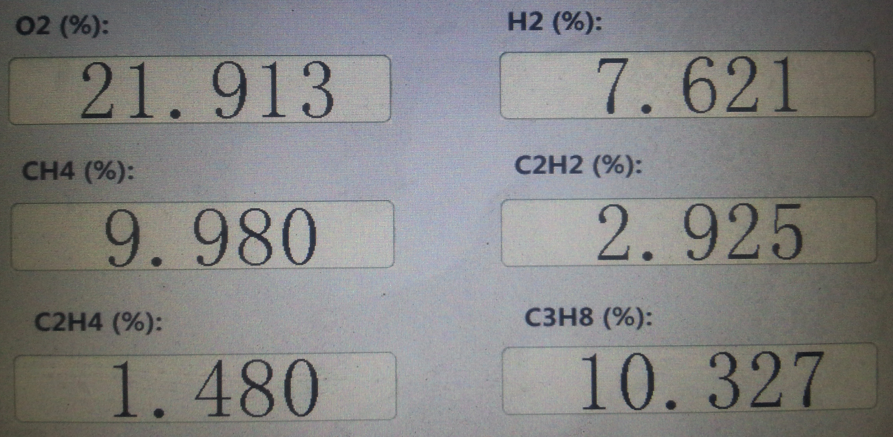
after the above experiments, the Devon serial port screen driver has reached the expectation. As for some more complex operation modes, they can also be realized on this basis.
Welcome to: