Coordinate system
The process of converting coordinates to standardized equipment coordinates and then to screen coordinates is usually carried out step by step, which is similar to the pipeline. In the pipeline, the vertices of the object will be transformed into multiple coordinate systems before they are finally transformed into screen coordinates. The advantage of transforming the coordinates of an object into several intermediate coordinate systems is that in these specific coordinate systems, some operations or operations are more convenient and easy, which will soon become obvious. There are five different coordinate systems that are important to us:
- Local space
- World space: the coordinates of the object will be transformed from local to world space; The transformation is implemented by a model matrix.
- View space: the observation space is the result of converting the world space coordinates into the coordinates in front of the user's field of view. The transformation from world space to observation space is realized by view matrix.
- Clip space: in order to transform vertex coordinates from observation to clipping space, we need to define a projection matrix, which specifies a range of coordinates, such as - 1000 to 1000 in each dimension. The projection matrix then transforms the coordinates within this specified range into the range of standardized equipment coordinates (- 1.0, 1.0). All coordinates outside the range will not be mapped between - 1.0 and 1.0, so they will be cropped out. The transformation from observation space to clipping space is realized by projection matrix.
The viewing box created by the projection matrix is called frustum, and each coordinate appearing within the range of frustum will eventually appear on the user's screen. The process of converting coordinates in a specific range to the standardized equipment coordinate system (and it is easy to be mapped to 2D observation space coordinates) is called projection, because 3D coordinates can be projected to the standardized equipment coordinate system that is easy to be mapped to 2D using the projection matrix.
Once all vertices are transformed into the clipping space, the final operation - perspective Division will be performed. In this process, we divide the x, y and z components of the position vector by the homogeneous w components of the vector; Perspective division is the process of transforming 4D clipping space coordinates into 3D standardized equipment coordinates. This step is automatically performed at the end of each vertex shader run.
After this stage, the final coordinates will be mapped into screen space (using the settings in glViewport) and transformed into fragments.
The projection matrix that transforms the observation coordinates into clipping coordinates can be in two different forms, each of which defines a different frustum. We can choose to create an orthographic projection matrix or a perspective projection matrix.
- Screen space
In order to transform coordinates from one coordinate system to another, we need to use several transformation matrices, the most important of which are model, view and projection.
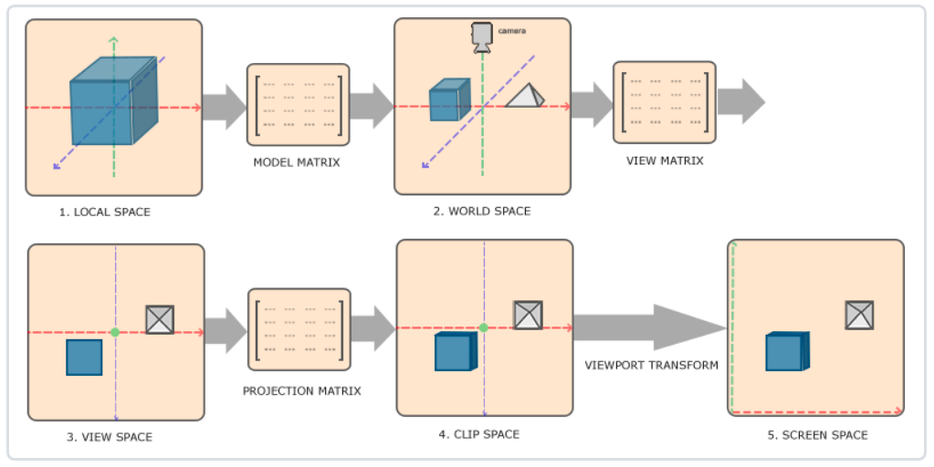
- Local coordinates are the coordinates of the object relative to the local origin and the starting coordinates of the object.
- The next step is to transform the local coordinates into world space coordinates, which are in a larger spatial range. These coordinates are relative to the global origin of the world, and they will be placed with other objects relative to the origin of the world.
- Next, we transform the world coordinates into observation space coordinates, so that each coordinate is observed from the perspective of the camera or observer.
- After the coordinates reach the observation space, we need to project them to the clipping coordinates. The clipping coordinates will be processed to the range of - 1.0 to 1.0, and determine which vertices will appear on the screen.
- Finally, we will transform the clipping coordinates into screen coordinates, and we will use a called Viewport transformation
Transform). Viewport transformation transforms the coordinates in the - 1.0 to 1.0 range to the coordinates defined by the glViewport function. Finally, the transformed coordinates will be sent to the raster and converted into fragments.
Orthophoto projection
The orthographic projection matrix defines a cube like truncated head box, which defines a clipping space in which vertices outside the space will be clipped. To create an orthographic projection matrix, you need to specify the width, height, and length of the visible frustum. After using the orthographic projection matrix to transform to the clipping space, all coordinates in the frustum body will not be clipped. Its frustum looks like a container:
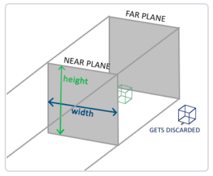
The above frustum defines the visible coordinates, which are specified by the width, height, near plane and far plane. Any coordinates that appear before the near plane or after the far plane are cropped out. Orthophoto frustum directly maps all coordinates inside the frustum to standardized equipment coordinates, because the w component of each vector is not changed; If the w component is equal to 1.0, the perspective division rule does not change this coordinate.
To create an orthographic projection matrix, we can use GLM's built-in function glm::ortho:
glm::ortho(0.0f, 800.0f, 0.0f, 600.0f, 0.1f, 100.0f);
The first two parameters specify the left and right coordinates of the frustum, and the third and fourth parameters specify the bottom and top of the frustum. Through these four parameters, we define the size of the near plane and the far plane, and then the fifth and sixth parameters define the distance between the near plane and the far plane. This projection matrix transforms the coordinates within these x, y, z values into standardized equipment coordinates.
The orthographic projection matrix directly maps the coordinates to the 2D plane, that is, your screen, but in fact, a direct projection matrix will produce unrealistic results because the projection does not take into account the perspective. So we need perspective projection matrix to solve this problem.
perspective projection
It is done using perspective projection matrix. This projection matrix maps the given frustum range to the clipping space. In addition, it also modifies the W value of each vertex coordinate, so that the farther away from the observer, the greater the w component of the vertex coordinate. The coordinates transformed into the clipping space will be in the range of - w to w (any coordinates larger than this range will be clipped). OpenGL requires that all visible coordinates fall within the range of - 1.0 to 1.0 as the final output of the vertex shader. Therefore, once the coordinates are in the clipping space, the perspective Division will be applied to the clipping space coordinates:
o
u
t
=
(
x
/
w
y
/
w
z
/
w
)
out = \begin{pmatrix} x /w \\ y / w \\ z / w \end{pmatrix}
out=⎝⎛x/wy/wz/w⎠⎞
Each component of the vertex coordinate is divided by its w component. The farther away from the observer, the smaller the vertex coordinate will be. This is another reason why the w component is very important. It can help us with perspective projection. The final result is the coordinates in the standardized equipment space. If you are interested in how orthographic projection matrix and perspective projection matrix are calculated (and you are not afraid of Mathematics), I recommend this article written by Songho article.
In GLM, you can create a perspective projection matrix as follows:
glm::mat4 proj = glm::perspective(glm::radians(45.0f), (float)width/(float)height, 0.1f, 100.0f);
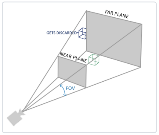
Similarly, what glm::perspective does is to create a large frustum that defines the visual space. Anything outside the frustum will not appear in the volume of the clipping space and will be clipped. A perspective frustum can be regarded as a box with uneven shape, and each coordinate in the box will be mapped to a point in the clipping space.
Its first parameter defines the value of fov, which represents the field of view and sets the size of the observation space. If you want a real observation effect, its value is usually set to 45.0f, but if you want a doomsday style result, you can set it to a larger value. The second parameter sets the aspect ratio, which is obtained by dividing the width of the viewport by the height. The third and fourth parameters set the near and far planes of the frustum. We usually set the short distance to 0.1f and the long distance to 100.0f. All vertices in the near and far planes and in the frustum body are rendered.
When you set the near value of the perspective matrix too large (such as 10.0f), OpenGL will cut off the coordinates close to the camera (between 0.0F and 10.0f), which will lead to a visual effect you are familiar with in the game: when you are too close to an object, your line of sight will go straight through.
Put them together
We have created a transformation matrix for each of the above steps: model matrix, observation matrix and projection matrix. A vertex coordinate will be transformed into a clipping coordinate according to the following procedure:
V
c
l
i
p
=
M
p
r
o
j
e
c
t
i
o
n
⋅
M
v
i
e
w
⋅
M
m
o
d
e
l
⋅
V
l
o
c
a
l
V_{clip} = M_{projection} \cdot M_{view} \cdot M_{model} \cdot V_{local}
Vclip=Mprojection⋅Mview⋅Mmodel⋅Vlocal
Code to achieve 3D effect
- Three matrices are added in the vertex shader code: model, view and projection. Note the multiplication order:
#version 330 core
layout(location = 0) in vec3 aPos;
......

uniform mat4 model;
uniform mat4 view;
uniform mat4 projection;

......
void main(){
    gl_Position = projection * view * model*vec4(aPos,1.0f);
    ......
}
- Configure several transformation matrices:
void ZjjOpenGLWidget::paintGL()
{
......
QMatrix4x4 model;
QMatrix4x4 view;
QMatrix4x4 projection;
// unsigned int time = QTime::currentTime().msec();
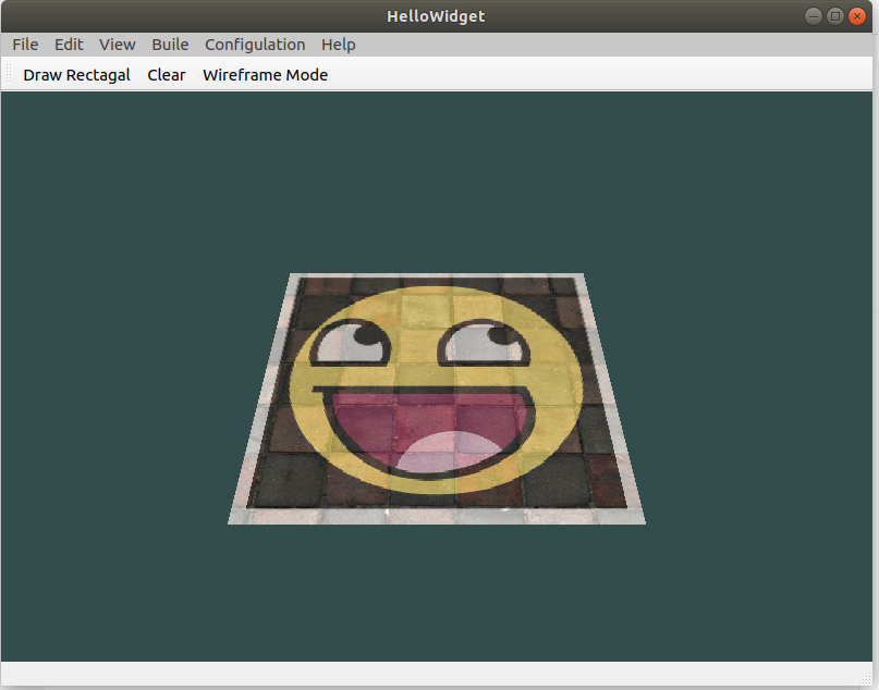
// Rotation in x-axis direction - 45 °
model.rotate(-45, 1.0f, 0.0f, 0.0f);
// Move - 1 (z axis) in global coordinate system
view.translate(0.0, 0.0, -2);
projection.perspective(45, (float)width()/height(), 0.1, 100);
......
switch (m_shape) {
case Rect:
{
textureWall->bind(0);
textureSmile->bind(1);
// textureNose->bind(2);
shaderProgram.setUniformValue("model", model);
shaderProgram.setUniformValue("view", view);
shaderProgram.setUniformValue("projection", projection);
glDrawElements(GL_TRIANGLES, 6, GL_UNSIGNED_INT, 0);
......
}
- Because the vertex data here have been given one by one, we don't use EBO to index for the time being.
float vertices[] = {
    -0.5f, -0.5f, -0.5f,  0.0f, 0.0f,
     0.5f, -0.5f, -0.5f,  1.0f, 0.0f,
     0.5f,  0.5f, -0.5f,  1.0f, 1.0f,
     0.5f,  0.5f, -0.5f,  1.0f, 1.0f,
    -0.5f,  0.5f, -0.5f,  0.0f, 1.0f,
    -0.5f, -0.5f, -0.5f,  0.0f, 0.0f,

    -0.5f, -0.5f,  0.5f,  0.0f, 0.0f,
     0.5f, -0.5f,  0.5f,  1.0f, 0.0f,
     0.5f,  0.5f,  0.5f,  1.0f, 1.0f,
     0.5f,  0.5f,  0.5f,  1.0f, 1.0f,
    -0.5f,  0.5f,  0.5f,  0.0f, 1.0f,
    -0.5f, -0.5f,  0.5f,  0.0f, 0.0f,

    -0.5f,  0.5f,  0.5f,  1.0f, 0.0f,
    -0.5f,  0.5f, -0.5f,  1.0f, 1.0f,
    -0.5f, -0.5f, -0.5f,  0.0f, 1.0f,
    -0.5f, -0.5f, -0.5f,  0.0f, 1.0f,
    -0.5f, -0.5f,  0.5f,  0.0f, 0.0f,
    -0.5f,  0.5f,  0.5f,  1.0f, 0.0f,

     0.5f,  0.5f,  0.5f,  1.0f, 0.0f,
     0.5f,  0.5f, -0.5f,  1.0f, 1.0f,
     0.5f, -0.5f, -0.5f,  0.0f, 1.0f,
     0.5f, -0.5f, -0.5f,  0.0f, 1.0f,
     0.5f, -0.5f,  0.5f,  0.0f, 0.0f,
     0.5f,  0.5f,  0.5f,  1.0f, 0.0f,

    -0.5f, -0.5f, -0.5f,  0.0f, 1.0f,
     0.5f, -0.5f, -0.5f,  1.0f, 1.0f,
     0.5f, -0.5f,  0.5f,  1.0f, 0.0f,
     0.5f, -0.5f,  0.5f,  1.0f, 0.0f,
    -0.5f, -0.5f,  0.5f,  0.0f, 0.0f,
    -0.5f, -0.5f, -0.5f,  0.0f, 1.0f,

    -0.5f,  0.5f, -0.5f,  0.0f, 1.0f,
     0.5f,  0.5f, -0.5f,  1.0f, 1.0f,
     0.5f,  0.5f,  0.5f,  1.0f, 0.0f,
     0.5f,  0.5f,  0.5f,  1.0f, 0.0f,
    -0.5f,  0.5f,  0.5f,  0.0f, 0.0f,
    -0.5f,  0.5f, -0.5f,  0.0f, 1.0f
};

void ZjjOpenGLWidget::initializeGL()
{
    ......
//    coordinate
    glVertexAttribPointer(0, 3, GL_FLOAT, GL_FALSE, 5*sizeof(float), (void*)0);
    glEnableVertexAttribArray(0);
//    Texture coordinates
    glVertexAttribPointer(1, 2, GL_FLOAT, GL_FALSE, 5*sizeof(float), (void*)(3*sizeof(float)));
    glEnableVertexAttribArray(1);

    ......
}

void ZjjOpenGLWidget::paintGL()
{
    ......
    switch (m_shape) {
    case Rect:
    {
        textureWall->bind(0);
        textureSmile->bind(1);
//        textureNose->bind(2);
        shaderProgram.setUniformValue("model", model);
        shaderProgram.setUniformValue("view", view);
        shaderProgram.setUniformValue("projection", projection);
//        glDrawElements(GL_TRIANGLES, 6, GL_UNSIGNED_INT, 0);
        glDrawArrays(GL_TRIANGLES, 0, 36);
        ......
}
The vertex shader is modified accordingly:
layout (location = 0) in vec3 aPos;
layout (location = 1) in vec2 aTexCoord;
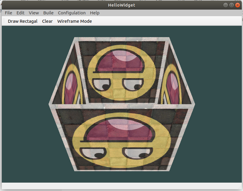
It's a bit like a cube, but it's strange. Some faces of the cube that should have been obscured are drawn on the other faces of the cube. This is because OpenGL draws your cube triangle by triangle, so even if there is something there before, it will cover the previous pixels. For this reason, some triangles will be drawn on top of others, although they should not have been covered.
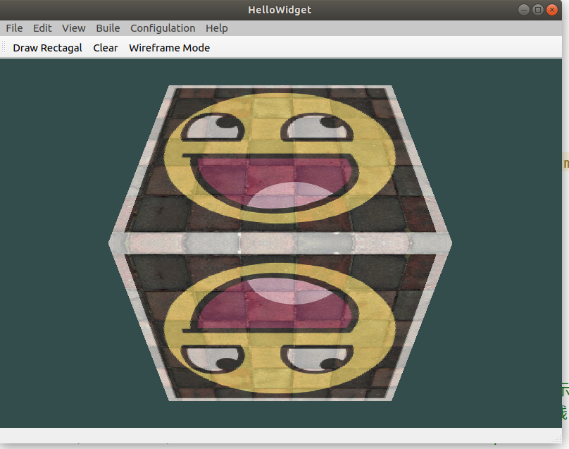
- Z-buffer
OpenGL stores all its depth information in a Z-buffer, also known as the depth buffer. GLFW will automatically generate such a buffer for you (just as it also has a color buffer to store the color of the output image). The depth value is stored in each clip (as the Z value of the clip). When the clip wants to output its color, OpenGL will compare its depth value with the Z buffer. If the current clip is behind other clips, it will be discarded, otherwise it will be overwritten. This process is called depth testing, which is automatically completed by OpenGL.
However, if we want to make sure that OpenGL really performs depth testing, first we have to tell OpenGL that we want to enable depth testing; It is off by default. We can turn on the depth test through the glEnable function. The glEnable and glDisable functions allow us to enable or disable an OpenGL feature. This function remains enabled / disabled until another call is used to disable / enable it. Now, if we want to enable the depth test, we need to turn on GL_DEPTH_TEST:
glEnable(GL_DEPTH_TEST);
Because we use the depth test, we also want to clear the depth buffer before each rendering iteration (otherwise the depth information of the previous frame is still stored in the buffer). Just like clearing the color buffer, we can specify depth in the glClear function_ BUFFER_ Bit bit to clear the depth buffer:
glClear(GL_COLOR_BUFFER_BIT | GL_DEPTH_BUFFER_BIT);
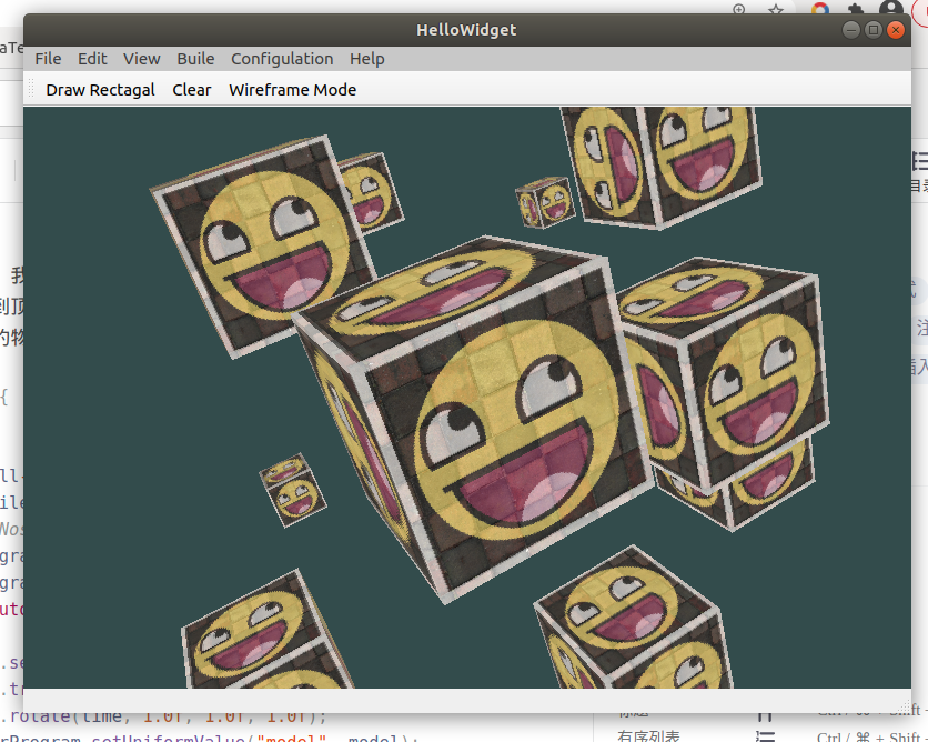
- Draw more cubes
Now we want to display 10 cubes on the screen. Every cube looks the same. The difference is that they have different positions and rotation angles in the world. The graphic layout of the cube has been defined, so when rendering more objects, we don't need to change our buffer array and attribute array. The only thing we need to do is change the model matrix of each object to transform the cube into the world coordinate system.
First, let's define a displacement vector for each cube to specify its position in world space:
QVector<QVector3D> cubePositions = {
    QVector3D( 0.0f,  0.0f,  0.0f),
    QVector3D( 2.0f,  5.0f, -15.0f),
    QVector3D(-1.5f, -2.2f, -2.5f),
    QVector3D(-3.8f, -2.0f, -12.3f),
    QVector3D( 2.4f, -0.4f, -3.5f),
    QVector3D(-1.7f,  3.0f, -7.5f),
    QVector3D( 1.3f, -2.0f, -2.5f),
    QVector3D( 1.5f,  2.0f, -2.5f),
    QVector3D( 1.5f,  0.2f, -1.5f),
    QVector3D(-1.3f,  1.0f, -1.5f)
  };
Now, in the game loop, we call glDrawArrays 10 times, but this time before we render, we pass a different model matrix into the vertex shader each time. We will create a small loop in the game loop and render our objects 10 times with different model matrices. Note that we also added a little rotation to each box:
switch (m_shape) {
    case Rect:
    {
        textureWall->bind(0);
        textureSmile->bind(1);
//        textureNose->bind(2);
        shaderProgram.setUniformValue("view", view);
        shaderProgram.setUniformValue("projection", projection);
        foreach(auto item, cubePositions)
        {
            model.setToIdentity();
            model.translate(item);
            model.rotate(time, 1.0f, 1.0f, 1.0f);
            shaderProgram.setUniformValue("model", model);
            glDrawArrays(GL_TRIANGLES, 0, 36);
        }
        break;
    }