1. Camera model
Pinhole camera model: the light passing through a specific point in space can pass through the pinhole (pinhole aperture). These beams are projected onto the image plane to form an image.
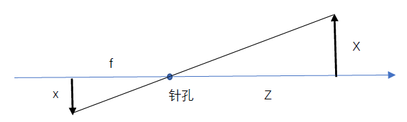
Put the image plane in front of the pinhole and reorganize the pinhole camera model into another equivalent form,
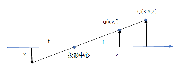
In fact, the center of the chip is usually not on the optical axis. Therefore, we introduce two new parameters cx and cy to model the possible offset (for the optical axis) of the coordinate center of the projection screen (image plane). In this way, the point Q in the physical world, whose coordinates are (X, Y, Z), is projected to a pixel position (xscreen,yscreen) on the imaging device according to the following formula:
xscreen = fx*X/Z+cx, and yscreen = fy*Y/Z+cy
We introduce two different focal lengths because a single pixel is rectangular rather than square on a low-cost imaging device. For example, focal length fx is actually the product of the physical focal length of the lens and the size sx of each unit of the imaging device (the meaning of this is that sx is in pixels / per millimetre and f is in millimeters, which means that fx is in pixels).
two Fundamentals of projective geometry
The process of mapping a series of physical points Q with coordinates (Xi, Yi, Zi) in the physical world to points with coordinates (xi, yi) on the projection plane is called "projective transformation". The formula is:
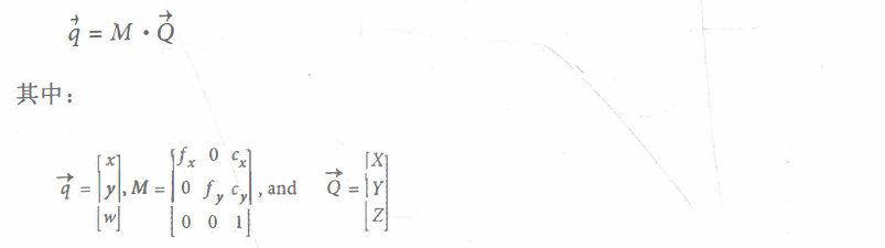
Where M is the internal parameter matrix of the camera and Q is the point of the physical world. The actual pixel coordinate value can be obtained by dividing the x and y coordinates of Q by w.
The functions cv::convertPointsToHomogeneous() and cv::convertPointsFromHomogeneous() allow us to convert between homogeneous and non-homogeneous coordinates.
With an ideal pinhole, only a small amount of light passes through the pinhole. In practice, no matter what kind of image collector is used, it needs to wait to accumulate enough light, so the imaging speed is very slow. For a camera that generates images quickly, it must use a larger area of light, or even bend the light, so that enough light can focus on the projection point We use a lens to achieve this. The lens can focus enough light to a point, making the image generation faster, but at the cost of introducing distortion.
3.Rodrigues transformation
When operating in three-dimensional space, the 3x3 matrix is usually used to represent the rotation in space. This representation is usually the most convenient, because multiplying the vector by the matrix is equivalent to rotating the vector in some way. The disadvantage is that it is difficult to understand what kind of rotation the 3x3 matrix represents. In addition, the rotation along a certain angle can be represented by a vector, and the direction of the vector represents the rotation axis The direction of the vector and the length of the vector represent the amount of rotation in the counterclockwise direction. This is easy to do because the direction can be represented by a vector of any amplitude. Therefore, we can choose that our vector amplitude is equal to the angle of rotation. The rotation vector and the rotation matrix can be transformed by Rodrigues transform. The rotation in three-dimensional space contains three degrees of freedom from the angle of numerical optimization In terms of degree, it is much more convenient to deal with Rodrigues representation with only three parts than 3x3 rotation matrix with several parts.
void Rodrigues( InputArray src, //Input rotation vector or matrix
          OutputArray dst, //Output rotation matrix or vector
          OutputArray jacobian = noArray() );
The last parameter is optional. If jacobian is not cv::noArray(), it should be a pointer to a 3x9 or 9x3 matrix, which will fill the partial derivatives of the output matrix elements relative to the input matrix elements. The output jacobian mainly uses the internal optimization of cv:: solvePnP() and cv::calibrateCamera() functions, using cv::Rodrigues() The function is mainly used to convert the output of cv:: solvePnP() and cv::calibrateCamera() from 1x3 or 3x1 axis angle vector in Rodrigues format to rotation matrix. At this time, jacobian can be set to cv::noArray().
Example:
#include <opencv.hpp>
using namespace cv;
using namespace std;
int main() {
    Mat r = (cv::Mat_<float>(3, 1) <<
        -2.100418, -2.167796, 0.273330);
    Mat R;
    Rodrigues(r, R, noArray());
    for (int i = 0; i < 3; i++)
    {
        for (int j = 0; j < 3; j++)
        {
            printf("%f ", R.at<float>(i,j));
        }
        printf("\n");
    }
    return 0;
}
result:
-0.036254 0.978364 -0.203692
0.998304 0.026168 -0.051995
-0.045539 -0.205232 -0.977653
4. Lens distortion
4.1 radial distortion
Radial distortion is caused by the shape of the lens. The light far from the center of the lens is more curved than the light near the center of the lens, resulting in significant distortion at the pixel position near the edge of the imaging device. It is also called cylindrical distortion.
For radial distortion, the (Optics) of the imaging device The distortion at the center is 0. As it moves towards the edge, the distortion becomes larger and larger. In fact, this distortion is very small and can be described by the first few terms of Taylor series expansion near r = 0. For cheap network cameras, we usually use the first two terms; the first term is usually called k1 and the second term is called k2. For cameras with large distortion, such as fisheye lens, we can To use the third radial distortion term k3. Generally, the radial position of a point on the imaging device can be adjusted according to the following equation:
xcorrected = x • (1 + k1r2 + k2r4 + k3r6)
ycorrected = y • (1 + k1r2 + k2r4+k3r6)
Here, (x, y) is the original position of the distortion point (on the imaging device), and (xcorrected, ycorrected) is the new position after correction. The following figure shows the offset of the rectangle due to radial distortion. With the increase of the radial distance from the optical center, the outer points on the rectangle are offset inward.
four point two Tangential distortion
This distortion is caused by manufacturing defects that make the lens not parallel to the imaging plane. In cheap cameras, this phenomenon occurs when the imaging device is stuck to the back of the camera. Tangential distortion can be expressed by two additional parameters P1 and P2:
xcorrected = x + [ 2p1xy + p2(r2 + 2x2)]
ycorrected = y + [ p1(r2 + 2y2) + 2p2xy ]
Therefore, we need a total of five distortion parameters. Because these five parameters are necessary in most OpenCV programs using them, they are put into a distortion vector, which is a 5x1 matrix, including k1,k2,p1,p2 and k3 (in order) There are many other types of distortions in the imaging system, but they have less impact than radial and tangential distortions. Therefore, neither we nor OpenCV will further deal with them.
5. Calibration
OpenCV provides some algorithms to help us calculate these internal parameters. The actual calibration process is completed through cv::calibrateCamera(). The calibration method is to aim the camera at a known structure with many independent identifiable points. By observing this structure from multiple perspectives, we can calculate the (relative) of the camera when taking each image Position and orientation and internal parameters of the camera. In order to provide multiple viewing angles, we need to rotate and move the object.
5.1 rotation matrix and translation variables
We already know that three angles can be used to represent three-dimensional rotation and three parameters (x,y, z) can be used to represent three-dimensional translation. Therefore, we currently have six parameters. The OpenCV camera internal parameter matrix has four parameters (fx, fy, cx and cy), so each view needs to solve 10 parameters (note that the camera internal parameters remain unchanged in different views). Using a flat object, we can quickly see that eight parameters are fixed for each view. Because the six parameters of rotation and translation will change in different views, for each view, we constrain two additional parameters, and then use them to solve the camera internal parameter matrix. Therefore, we need (at least) two views to solve all geometric parameters.
5.2 calibration plate
OpenCV selects to use multiple views of planar objects instead of one view of specially constructed 3D objects. For now, we will focus on the chessboard model. Use alternating patterns of black and white squares to ensure that there is no bias to one side or the other in the measurement.
five point three Camera calibration
First of all, it should be noted that the external parameters include 3 rotation parameters and 3 translation parameters. There are 6 external parameters in each chessboard view. 10 parameters to be solved are composed of 4 parameters and 6 external parameters of the camera internal parameter matrix. In the case of a single view, 6 parameters will be added to each additional view.
Suppose there are N corners and K chessboard images (different positions). How many views and corners do we need to see to have enough constraints to solve all these parameters?
• K chessboard images provide 2 · N · K constraints (the occurrence factor 2 is because each point on the image has two coordinate values of x and y)
• ignoring each distortion parameter, we have 4 internal parameters and 6 · K external parameters (because we need to find 6 parameters of chessboard position in K views).
• the premise of solution is 2 · N · K ≥ 6 · K+4.
So it seems that if N = 5, then we only need the image of K = 1, but pay attention! No matter how many corners we find on the plane, we only get four useful corner information, so we need at least two views to solve our calibration problem. In practice, in order to obtain the effect of high-quality batch, at least 10 7X8 or larger chessboard images are required (only chessboard moving enough times between images can obtain "rich" views).
5.4 use CV:: findcheckboardcorners() to find chessboard corners ★★★
Given a chessboard image (or a person holding a chessboard, or any scene with a chessboard and a suitable non-interference background), you can use the function cv::findChessboardCorners() to locate the corners of the chessboard. If all corners can be found and sorted, the return value is set to true, otherwise it is false.
bool findChessboardCorners( InputArray image,  //Must be an 8bit image
                  Size patternSize, //Chessboard, 8UC1 OR 8UC3
                  OutputArray corners, //How many corner Size(cols,rows) are there in each row and column of the chessboard
                              int flags = CALIB_CB_ADAPTIVE_THRESH + CALIB_CB_NORMALIZE_IMAGE );
                  //Used to implement one or more additional filtering steps to help find corners on the chessboard
Subpixel corners and cv::cornerSubPix() on the chessboard
The internal algorithm used by findChessboardCorners() only provides approximate positions of corners. Therefore, cornersuppix() is automatically called by indChessboardCorners() to obtain more accurate results. In practice, this means that these positions are relatively accurate. However, if you want to locate them with very high accuracy, you need to call cornersuppix() on the output (call it again effectively), but a more stringent termination condition is required.
5.5 use CV:: drawcheckboardcorners() to draw chessboard corners ★★★
The function cv::drawChessboardCorners() draws the corners found by cv::findChessboardCorners() onto the image you provide. If all corners are not found, the available corners will be represented as small red circles. If the corners on the whole pattern are found, the corners will be drawn in different colors (each line will have its own color) And connect the corners with lines in a certain order.
void drawChessboardCorners( InputOutputArray image, //Since the corners are represented by colored circles, they must be 8-bit color images.
                  Size patternSize,
                              InputArray corners,
                  bool patternWasFound );//Are the corners on the whole chessboard pattern found successfully
five point six cv::calibrateCamera() get camera internal parameters and object external parameters ★★★
double calibrateCamera( InputArrayOfArrays objectPoints,//It is an integer in the x and y dimensions and zero in the z dimension
                InputArrayOfArrays imagePoints, //Position of each point in the image
                    Size imageSize,//The size of the image in pixels
                        InputOutputArray cameraMatrix, //Contains linear intrinsic parameters, should be 3x3 matrix
                InputOutputArray distCoeffs,//Distortion parameter, which can be 4, 5 or 8 elements
                        OutputArrayOfArrays rvecs, //Rotation matrix (in Rodrigues form)
                  OutputArrayOfArrays tvecs,//translation matrix
                        int flags = 0,
                   TermCriteria criteria = TermCriteria(//Termination criteria
                        TermCriteria::COUNT + TermCriteria::EPS, 30, DBL_EPSILON) );
The flags parameter allows more precise control of the calibration process. The following values can be combined with the Boolean OR operation as needed.
- CALIB_USE_INTRINSIC_GUESS
No other information is required when calculating the internal parameter matrix. Specifically, the parameters cx and cy (image center) The initial value of is obtained directly from the imageSize parameter. If this parameter is set, it is assumed that the cameraMatrix contains a valid value, which will be further optimized as the initial guess value. In many practical applications, we know the focal length of the camera because we can read them from the side of the lens. In this case, put this information into the camera matrix and use CV:: ca Lib_use_intrinsic_guess is a good idea.
- CALIB_FIX_PRINCIPAL_POINT
This flag can be used in combination with CALIB_USE_INTRINSIC_GUESS or alone. If used alone, the main point is fixed in the image center; if used together, the main point is fixed in the initial value provided in cameraMatrix.
- CALIB FIX ASPECT RATIO
If this flag is set, the optimization process will change fx and fy together when calling the calibration program, and their ratio will remain at the value set in cameraMatrix. If the CV:: calib_use_intrinsic_guess flag is not set, the values of fx and fy in cameraMatrix can be any value, but their ratio is related.
- CALIB FIX FOCAL LENGTH
This flag directly uses fx and fy passed in cameraMatrix during optimization
- CALIB_FIX_K1, cv::CAlIB_FIX_K2, ... cv::CALIB_FIX_K6
The radial distortion parameters K 1, K2 to k6 are corrected. The radial parameters can be set by combining these flags.
- CALIB RATIONAL MODEL
This flag tells OpenCV to calculate k4, k5 and k6 and from the three distortion coefficients. This is because of backward compatibility. If this flag is not added, only the first three K parameters will be calculated (even if you provide an eight element matrix for distCoeffs).
5.7 known internal parameters and calculated external parameters
-
Only cv::solvePnP() is used to calculate external parameters
In some cases, we already know the intrinsic parameters of the camera, so we only need to calculate the position of the object being observed. This situation is obviously different from the general camera calibration, but it is still a useful work.
bool solvePnP( InputArray objectPoints, InputArray imagePoints,
               InputArray cameraMatrix, InputArray distCoeffs,
               OutputArray rvec, OutputArray tvec,
               bool useExtrinsicGuess = false, int flags = SOLVEPNP_ITERATIVE );
The parameters of solvePnP() are similar to those of calibrateCamera(), but there are two differences:
1) The objectpoints and imagePoints parameters are parameters from a single view of the object (that is, they are of type cv::InputArray instead of cv::InputArrayOfArrays).
2) The internal parameter matrix and distortion coefficient are provided directly without calculation (i.e., they are inputs rather than outputs).
The output rotation vector is expressed in the form of Rodrigues: the rotation vector composed of three parts represents the three-dimensional coordinate axis of chessboard or point rotation, and the amplitude or length of the vector represents the counterclockwise rotation angle. This rotation vector can be converted into the 3x3 rotation matrix we discussed earlier through the cv::Rodrigues() function. The translation vector is the offset of the chessboard origin in the camera coordinates.
The useexternalicguess parameter can be set to true to indicate that the current value in the rvec and tvec parameters should be treated as the initial guess value of the solution. The default value is false.
The parameter flags can be set to one of three values, namely CV:: it iterative, CV:: P3P or cv:: EPNP, to indicate which method should be used to solve the whole system. When cv::ITERATIVE is used, Levenberg will be used-
-
Only cv::solvePnPRansac() is used to calculate external parameters
One disadvantage of CV:: solvepnp is that it is not robust enough to outliers. This is not a problem in camera calibration, mainly because the chessboard itself provides us with a reliable method to find various features we care about, and verify that the real object we are looking at is consistent with what we think through their relative geometric position. However, when we use the camera to locate Mismatches may occur and lead to serious problems when we are not talking about points on the chessboard but points in the real world (for example, using sparse key features). Recall that we talked about homography earlier that RANSAC method can be an effective method to deal with such outliers:
bool solvePnPRansac( InputArray objectPoints, InputArray imagePoints,
                     InputArray cameraMatrix, InputArray distCoeffs,
                     OutputArray rvec, OutputArray tvec,
                     bool useExtrinsicGuess = false, int iterationsCount = 100,
                     float reprojectionError = 8.0, double confidence = 0.99,
                     OutputArray inliers = noArray(), int flags = SOLVEPNP_ITERATIVE );
The RANSAC algorithm is also controlled by some new parameters. Specifically, the iterationsCount parameter sets the number of RANSAC iterations,
The reprojectionError parameter indicates the maximum re projection error of setting a point as an internal point. Note 39 the naming of the parameter mininliersCount is misleading. If the number of internal points exceeds mininliersCount when running RANSAC, the process will be terminated and the group will be considered as an internal point group. This can significantly improve the performance, but it will also occur if it is set too low Many problems. Finally, the inliers parameter is an output. If provided, it will be filled with the index value of the internal point (from objectPoints to imagePoints).
6. Correction
The corrected image is generated by inputting the original image and the distortion coefficient obtained by the function calibrateCamera(). We can either use the function undo() to complete the required tasks at one time, or use a pair of functions initUndistortRectifyMap() and remap() To deal with this more effectively, which is usually applicable to video or applications that obtain multiple images in the same camera.
6.1 correction mapping
When performing image correction, we must specify the position to which each pixel in the input image moves in the output image, which is called correction mapping (or sometimes distortion mapping). Such mapping has the following representations: dual channel floating-point representation, dual matrix floating-point representation and fixed-point representation.
6.2 use cv::convertMaps() to convert the mapping between different representations
Because there are multiple representations in the correction map, people naturally want to convert between these representations. We can do this with the cv::convertMaps() function. This function allows you to provide
6.3 use cv::initUndistortRectifyMap() to calculate correction mapping ★★★
void initUndistortRectifyMap(InputArray cameraMatrix, InputArray distCoeffs,
                             InputArray R, //Compensates for the rotation of the camera relative to the global coordinate system in which the camera is located
                  InputArray newCameraMatrix,//  For monocular images, set to noArray()
                             Size size, //Size of output mapping
                  int m1type, //The final mapping type, which may be CV_32FC1 or CV_16SC2
                  OutputArray map1, OutputArray map2);
6.4 use cv::remap() to correct the image ★★★
Once the correction mapping is calculated, you can use cv::remap() to apply them to the incoming image. As mentioned earlier, the cv::remap() function has two mapping parameters corresponding to the correction mapping, such as the mapping parameters calculated by cv::initUndistortRectifyMap(). cv::remap()) Accept any corrective mapping format we discuss: dual channel floating-point, dual matrix floating-point, or fixed-point format (with or without interpolation table index matrix).
void remap( InputArray src, OutputArray dst,
            InputArray map1, InputArray map2,//Map parameters calculated by initUndistortRectifyMap()
            int interpolation, int borderMode = BORDER_CONSTANT,
            const Scalar& borderValue = Scalar());
6.5 use CV:: undo() to correct ★★★
In some cases, you only need to correct one image or recalculate the correction mapping for each image. In this case, you can use the more concise undo (), which can effectively calculate the mapping and apply it to a single image.
void undistort( InputArray src, OutputArray dst,
                InputArray cameraMatrix,
                InputArray distCoeffs,
                InputArray newCameraMatrix = noArray() );
6.6 sparse correction using CV:: undisportpoints()
Just correct what you care about.
7. Examples
#include<iostream>
#include<opencv2\opencv.hpp>

using namespace std;
using namespace cv;

int main(int argc, char* argv[]) {

    int n_boards = 10;
    float image_sf = 0.5f;
    float delay = 1.f;
    int board_w = 3;
    int board_h = 3;
    int board_n = board_w * board_h;
    Size board_sz = Size(board_w, board_h);

    //Turn on the camera
    VideoCapture capture(0);
    if (!capture.isOpened()) {
        cout << "\nCouldn't open the camera\n";
        return -1;
    }

    //Allocate storage space
    vector<vector<Point2f>> image_points;
    vector<vector<Point3f>> object_points;

    double last_captured_timestamp = 0;
    Size image_size;

    //Keep taking pictures until you get enough n_boards Zhang
    while (image_points.size() < (size_t)n_boards) {
        Mat image0, image;
        capture >> image0;
        image_size = image0.size();
        resize(image0, image, Size(), image_sf, INTER_LINEAR);

        //Find the board
        vector<Point2f> corners;
        bool found = findChessboardCorners(image, board_sz, corners);

        //Draw it
        drawChessboardCorners(image, board_sz, corners, found);

        double timestamp = (double)clock() / CLOCKS_PER_SEC;

        if (found && timestamp - last_captured_timestamp > 1) {
            last_captured_timestamp = timestamp;
            image ^= Scalar::all(255);
            Mat mcorners(corners);
            mcorners *= (1. / image_sf);
            image_points.push_back(corners);
            object_points.push_back(vector<Point3f>());
            vector<Point3f>& opts = object_points.back();
            opts.resize(board_n);
            for (int j = 0; j < board_n; j++) {
                opts[j] = Point3f((float)(j / board_w), (float)(j % board_w), 0.f);
            }
            cout << "Collected our " << (int)image_points.size() << "of" << n_boards << "needed chessboard images\n" << endl;
        }
        imshow("calibration", image);
        if ((waitKey(30) & 255) == 27)
            return -1;
    }
    destroyWindow("calibration");
    cout << "\n\n*** CALIBRATIING THE CAMERA... \n" << endl;

    //Calibrate the camera
    Mat intrinsic_matrix, distortion_coeffs;
    double err = calibrateCamera(
        object_points,
        image_points,
        image_size,
        intrinsic_matrix,
        distortion_coeffs,
        noArray(), noArray(),
        CALIB_ZERO_TANGENT_DIST | CALIB_FIX_PRINCIPAL_POINT);

    //Save camera internal reference distortion
    cout << "***DONE!\n\n Reprojection error is" << err << "\nStoring Intrinsics.xml and Distortions.xml files\n\n";
    FileStorage fs("intrinsics.xml", FileStorage::WRITE);
    fs << "image_width" << image_size.width << "image_height" << image_size.height
        << "camera_matrix" << intrinsic_matrix << "distortion_coeffs" << distortion_coeffs;
    fs.release();

    //Load these parameters
    fs.open("intrinsics.xml", FileStorage::READ);
    cout << "\nimage width:" << (int)fs["image_width"];
    cout << "\nimage height:" << (int)fs["image_height"];

    Mat intrinsic_matrix_loaded, distortion_coeffs_loaded;
    fs["camera_matrix"] >> intrinsic_matrix_loaded;
    fs["distortion_coeffs"] >> distortion_coeffs_loaded;
    cout << "\nintrinsic matrix:" << intrinsic_matrix_loaded;
    cout << "\ndistortion coefficients:" << distortion_coeffs_loaded << endl;

    //Corrective mapping
    Mat map1, map2;
    initUndistortRectifyMap(
        intrinsic_matrix_loaded,
        distortion_coeffs_loaded,
        Mat(),
        intrinsic_matrix_loaded,
        image_size,
        CV_16SC2,
        map1,
        map2
    );

    //Incoming image,It shows an image without distortion
    for (;;) {
        Mat image, image0;
        capture >> image0;
        if (image0.empty()) break;
        remap(
            image0,
            image,
            map1,
            map2,
            INTER_LINEAR,
            BORDER_CONSTANT,
            Scalar()
        );
        imshow("Undistorted", image);
        if ((waitKey(30) & 255) == 27) break;
    }
    return 0;
}
result:

<?xml version="1.0"?>

-<opencv_storage>

<image_width>640</image_width>

<image_height>480</image_height>


-<camera_matrix type_id="opencv-matrix">

<rows>3</rows>

<cols>3</cols>

<dt>d</dt>

<data>5.7907667726308171e+02 0. 3.1950000000000000e+02 0.1.1801417596095703e+03 2.3950000000000000e+02 0. 0. 1.</data>

</camera_matrix>


-<distortion_coeffs type_id="opencv-matrix">

<rows>1</rows>

<cols>5</cols>

<dt>d</dt>

<data>1.3156136239488735e-02 -2.0824275792988209e-01 0. 0. -3.1422421138402745e-01</data>

</distortion_coeffs>

</opencv_storage>
Supplement:
1. About why
(waitKey(30) & 255) == 27
article https://blog.csdn.net/hao5119266/article/details/104173400 Explained it in detail.
two The difference between image_points and object_points
image_points is the pixel coordinates of points on the image, and object_points is the position of (0,0,0) (0,1,0)
The size of object_points is the number of calibrated pictures. Print an object_points, as shown below
[0, 0, 0;
 0, 1, 0;
 0, 2, 0;
 0, 3, 0;
 1, 0, 0;
 1, 1, 0;
 1, 2, 0;
 1, 3, 0;
 2, 0, 0;
 2, 1, 0;
 2, 2, 0;
 2, 3, 0;
 3, 0, 0;
 3, 1, 0;
 3, 2, 0;
 3, 3, 0]
3. Why is the z dimension of opts 0, that is, the z dimension of object_points 0
opts[j] = Point3f((float)(j / board_w), (float)(j % board_w), 0.f);
Our focus is not the coordinates of all spaces, but the coordinates on the observation plane, so make some simplification and choose to define the object plane so that Z=0. (I guess, I don't know sister Li)


From Chapter 18 of butterfly book P553-P597