On timer module
- 1, Basic concepts
- 1. Timing and counting
- 2. Main features of timer
- 3. Timer family
- 4. Main functions
- 5. Conventional timer classification
- 2, Internal structure
1, Basic concepts
1. Timing and counting
-
Counter: count the number of pulses (the pulses can be fixed or not) to realize the function of measurement, counting and control, and also have the function of frequency division, such as the external pulse signal introduced by the I/O pin of MCU.
-
Timer: count the pulse signal with fixed cycle, such as the peripheral clock inside MCU.
Timing and timing:
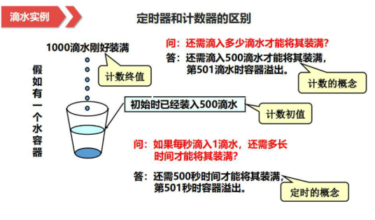
Summary: the essence of timer is counter, timer is a special counter.
2. Main features of timer
The timer has three characteristics: bit width, calculation value and processing.
- Bit width: bit width is the counting range of timer, for example, the counting range of 16 bit timer is 0 ~ 65535
- Count value: count value is divided into timer initial value and timer final value. The initial value of the timer is the value set when the timer starts to count. The final value of the timer is set by the user. The timer starts to count from the initial value. When this value is reached, the timer overflows.
- Handling: operations to be completed after timer overflow.
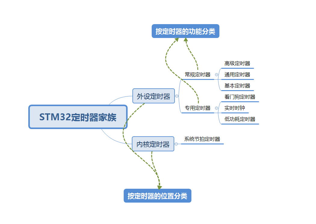
3. Timer family
4. Main functions
-
Timing counting: counting internal clock, i.e. timer mode; counting external pulse, i.e. counter mode.
-
Output comparison: this function is used to control the output waveform or indicate that a certain period of time has passed. They are PWM output, level flip, single pulse output and forced output.
-
Input acquisition: the type of captured signal edge can be selected (rising edge, falling edge, bilateral edge); it can be used to measure the pulse width (input acquisition), signal frequency, period and phase difference of input signal.
Timer can be used as digital frequency meter, intelligent household appliances, timing control equipment and motor drive.
5. Conventional timer classification
- Basic timer: almost no input / output channels, commonly used as a time base, to achieve basic timing / counting functions.
- General timer: with multiple independent acquisition and comparison channels, it can complete timing / counting, input acquisition, output comparison and other functions.
- Advanced timer: in addition to the general timer function, it also has complementary signal output with dead zone control, emergency brake off input and other functions, which can be used for motor control and digital power supply design.
Personal experience: Advanced timers are widely used in power electronics to control multiphase SPWM wave output.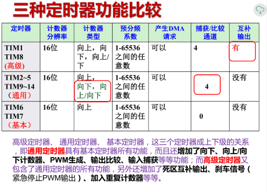
2, Internal structure
1. General timer structure
Timer is to count the pulse of fixed period, so as to get the time reference, and then realize the timing function.
The construction of timer is divided into four parts: clock source selection, timer time base unit, input capture and output comparison.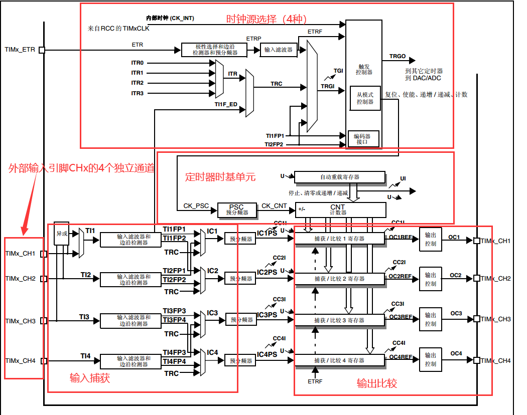
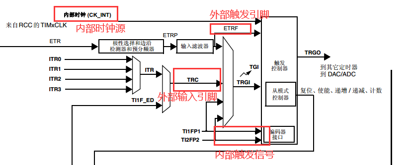
2. Clock source selection
The clock source selection determines where the clock source comes from. There are four sources in total:
① Internal clock source CK_IINT ;
② External clock mode 2: external trigger input (ETR), only applicable to TIM2, TIM3 and TIM4;
③ External clock mode 1: external input pin (TIx);
④ External trigger input (ITRx): a prescaler that uses one timer as another, such as timing
It is configured as a prescaler of timer 2.
3. Time base unit
The main module of timer consists of a 16 bit / 32-bit counter and its related automatic reload register. This counter can be incremented (Advanced timers also have decrements or alternately increments and decrements).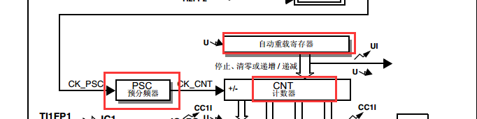
Time base unit includes:
● counter register (TIMx_CNT)
● prescaler register (TIMx_PSC)
● automatic overload register (TIMx_ARR)
● repeat counter register (TIMx_RCR) [unique to advanced timer]
The clock of the counter can be divided by prescaler. Counter, automatic overload register and prescaler register can be read and written by software. Read and write operations can be performed even when the counter is running. In the timer time base unit, the count value required for timing can be set. There are two parameters that need to be set, namely the prescaled coefficient PSC and the automatic reload value ARR.
4. counting method
-
Up count mode (up count mode)
In up count mode, the counter counts from 0 to the automatic overload value (timx_ The contents of the ARR register) and then start counting again from 0 and generate a counter overflow event. If a repeat counter is used, the number of times the count is incremented reaches the number programmed in the repeat counter register plus one time (timx_ After RCR + 1), an update event (UEV) is generated. Otherwise, an update event is generated each time the counter overflows. Put timx_ An update event is also generated when UG position 1 of the EGR register (via software or using the slave mode controller).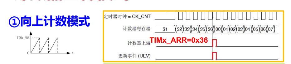
-
Decrement mode (decrement mode)
In decrement count mode, the counter is overloaded from the automatic value (timx_ The contents of the ARR register) start decrementing to 0, and then start counting again from the auto overload value and generate a counter underflow event. If a repeat counter is used, when the number of decrements reaches the number of times programmed in the repeat counter register plus one time (timx_ After RCR + 1), an update event (UEV) is generated. Otherwise, an update event is generated each time the counter overflows.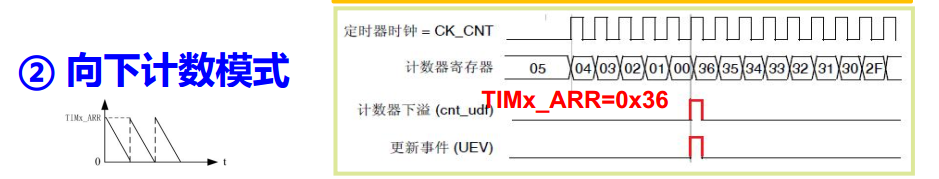
-
Center alignment mode (count up, count down)
In center aligned mode, the counter counts from 0 to the auto reload value (timx_ Contents of the ARR register) - 1,
Generates a counter overflow event; then counts down to 1 from the auto overload value and generates a counter underflow event. Then from
0 starts recount.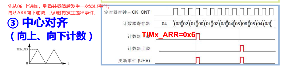
5. Frequency calculation
Timer timing period:
Tout=[(ARR+1)*(PSC+1)]/TCK-INT
Where: ARR is the reload value, PSC is the frequency division coefficient, and TCK-INT is the internal clock period
Timer timing frequency:
fout=fCK-INT /[(ARR+1)*(PSC+1)]
Where: fck int is the internal clock frequency
6. Relevant data structure
Note: the following content is based on STM32CubeMX hal Library
6.1 basic configuration structure of timer
typedef struct
{
  uint32_t Prescaler;         /*Set the prescaler coefficient, because it is 16 bit, so it is between 0x0000 and 0xFFFF */

  uint32_t CounterMode;       /*Set the count mode, align up, down or center*/

  uint32_t Period;            /*Reload value, between 0x0000 and 0xFFFF*/

  uint32_t ClockDivision;     /*Clock frequency division, set timer clock CK_INT frequency and sampling clock of digital filter
 Frequency division ratio, basic timer does not have this function, do not need to set. */

  uint32_t RepetitionCounter;  /*Whether to turn on the repeat count, i.e. control the RCR register, which is used by the advanced timer*/
} TIM_Base_InitTypeDef;
6.2 timer initialization parameter structure
typedef struct
{
  TIM_TypeDef                 *Instance;     /*Timer selected*/
  TIM_Base_InitTypeDef        Init;          /*Basic configuration structure*/
  HAL_TIM_ActiveChannel       Channel;       /*passageway */
  DMA_HandleTypeDef           *hdma[7U];     /*DMA Related configuration*/
  HAL_LockTypeDef             Lock;          /*!< Locking object                    */
  __IO HAL_TIM_StateTypeDef   State;         /*!< TIM operation state               */
}TIM_HandleTypeDef;
6.3 timer initialization function
HAL_StatusTypeDef HAL_TIM_Base_Init(TIM_HandleTypeDef *htim);
6.4 timer callback function
HAL_StatusTypeDef HAL_TIM_Base_Start_IT(TIM_HandleTypeDef *htim);//Turn on timer
HAL_StatusTypeDef HAL_TIM_Base_Stop_IT(TIM_HandleTypeDef *htim);//off timer
6.5 timer timing callback function
void HAL_TIM_PeriodElapsedCallback(TIM_HandleTypeDef *htim)
Callback function is a kind of encapsulation way of HAL Library in order to improve portability. We can find that when the timer breaks, it responds to the corresponding interrupt, enters the interrupt service function, and then calls the corresponding callback function in the interrupt service function
void HAL_TIM_IRQHandler(TIM_HandleTypeDef *htim)
{
  /* Capture compare 1 event */
  if(__HAL_TIM_GET_FLAG(htim, TIM_FLAG_CC1) != RESET)
  {
    if(__HAL_TIM_GET_IT_SOURCE(htim, TIM_IT_CC1) !=RESET)
    {
      {
        __HAL_TIM_CLEAR_IT(htim, TIM_IT_CC1);
        htim->Channel = HAL_TIM_ACTIVE_CHANNEL_1;

        /* Input capture event */
        if((htim->Instance->CCMR1 & TIM_CCMR1_CC1S) != 0x00U)
        {
          HAL_TIM_IC_CaptureCallback(htim);
        }
        /* Output compare event */
        else
        {
          HAL_TIM_OC_DelayElapsedCallback(htim);
          HAL_TIM_PWM_PulseFinishedCallback(htim);
        }
        htim->Channel = HAL_TIM_ACTIVE_CHANNEL_CLEARED;
      }
    }
  }
  /* Capture compare 2 event */
  if(__HAL_TIM_GET_FLAG(htim, TIM_FLAG_CC2) != RESET)
  {
    if(__HAL_TIM_GET_IT_SOURCE(htim, TIM_IT_CC2) !=RESET)
    {
      __HAL_TIM_CLEAR_IT(htim, TIM_IT_CC2);
      htim->Channel = HAL_TIM_ACTIVE_CHANNEL_2;
      /* Input capture event */
      if((htim->Instance->CCMR1 & TIM_CCMR1_CC2S) != 0x00U)
      {
        HAL_TIM_IC_CaptureCallback(htim);
      }
      /* Output compare event */
      else
      {
        HAL_TIM_OC_DelayElapsedCallback(htim);
        HAL_TIM_PWM_PulseFinishedCallback(htim);
      }
      htim->Channel = HAL_TIM_ACTIVE_CHANNEL_CLEARED;
    }
  }
  /* Capture compare 3 event */
  if(__HAL_TIM_GET_FLAG(htim, TIM_FLAG_CC3) != RESET)
  {
    if(__HAL_TIM_GET_IT_SOURCE(htim, TIM_IT_CC3) !=RESET)
    {
      __HAL_TIM_CLEAR_IT(htim, TIM_IT_CC3);
      htim->Channel = HAL_TIM_ACTIVE_CHANNEL_3;
      /* Input capture event */
      if((htim->Instance->CCMR2 & TIM_CCMR2_CC3S) != 0x00U)
      {
        HAL_TIM_IC_CaptureCallback(htim);
      }
      /* Output compare event */
      else
      {
        HAL_TIM_OC_DelayElapsedCallback(htim);
        HAL_TIM_PWM_PulseFinishedCallback(htim);
      }
      htim->Channel = HAL_TIM_ACTIVE_CHANNEL_CLEARED;
    }
  }
  /* Capture compare 4 event */
  if(__HAL_TIM_GET_FLAG(htim, TIM_FLAG_CC4) != RESET)
  {
    if(__HAL_TIM_GET_IT_SOURCE(htim, TIM_IT_CC4) !=RESET)
    {
      __HAL_TIM_CLEAR_IT(htim, TIM_IT_CC4);
      htim->Channel = HAL_TIM_ACTIVE_CHANNEL_4;
      /* Input capture event */
      if((htim->Instance->CCMR2 & TIM_CCMR2_CC4S) != 0x00U)
      {
        HAL_TIM_IC_CaptureCallback(htim);
      }
      /* Output compare event */
      else
      {
        HAL_TIM_OC_DelayElapsedCallback(htim);
        HAL_TIM_PWM_PulseFinishedCallback(htim);
      }
      htim->Channel = HAL_TIM_ACTIVE_CHANNEL_CLEARED;
    }
  }
  /* TIM Update event */
  if(__HAL_TIM_GET_FLAG(htim, TIM_FLAG_UPDATE) != RESET)
  {
    if(__HAL_TIM_GET_IT_SOURCE(htim, TIM_IT_UPDATE) !=RESET)
    {
      __HAL_TIM_CLEAR_IT(htim, TIM_IT_UPDATE);
      HAL_TIM_PeriodElapsedCallback(htim);
    }
  }
  /* TIM Break input event */
  if(__HAL_TIM_GET_FLAG(htim, TIM_FLAG_BREAK) != RESET)
  {
    if(__HAL_TIM_GET_IT_SOURCE(htim, TIM_IT_BREAK) !=RESET)
    {
      __HAL_TIM_CLEAR_IT(htim, TIM_IT_BREAK);
      HAL_TIMEx_BreakCallback(htim);
    }
  }
  /* TIM Trigger detection event */
  if(__HAL_TIM_GET_FLAG(htim, TIM_FLAG_TRIGGER) != RESET)
  {
    if(__HAL_TIM_GET_IT_SOURCE(htim, TIM_IT_TRIGGER) !=RESET)
    {
      __HAL_TIM_CLEAR_IT(htim, TIM_IT_TRIGGER);
      HAL_TIM_TriggerCallback(htim);
    }
  }
  /* TIM commutation event */
  if(__HAL_TIM_GET_FLAG(htim, TIM_FLAG_COM) != RESET)
  {
    if(__HAL_TIM_GET_IT_SOURCE(htim, TIM_IT_COM) !=RESET)
    {
      __HAL_TIM_CLEAR_IT(htim, TIM_FLAG_COM);
      HAL_TIMEx_CommutationCallback(htim);
    }
  }
}