1, I2C introduction
1. IC2 introduction
I2C communication protocol (Inter Integrated Circuit) is developed by Phiilps company. It has the advantages of few pins, simple hardware implementation, strong scalability and no need for external transceiver equipment of USART, CAN and other communication protocols.
The connection mode of I2C on communication equipment is shown in the figure:
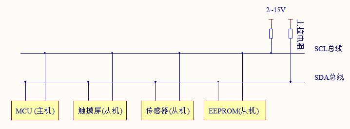
As can be seen from the figure, it only needs two wires to transmit data between devices connected to the bus.
2. Working principle
SDA (serial data line) and SCL (serial clock line) are bidirectional I/O lines, and the interface circuit is open drain output. The power supply VCC needs to be connected through the pull-up resistor. When the bus is idle, both lines are high-level, the external devices connected to the bus are CMOS devices, and the output stage is also open drain circuit. The current consumed on the bus is very small, so, The number of devices expanded on the bus is mainly determined by the capacitive load, because the bus interface of each device has a certain equivalent capacitance. The capacitance in the line will affect the bus transmission speed. When the capacitance is too large, it may cause transmission errors. Therefore, its load capacity is 400pF, so the allowable length of the bus and the number of connected devices can be estimated.
The master device is used to start the bus to transmit data and generate a clock to open the transmission. At this time, any addressed device is considered as a slave device. The relationship between master and slave, transmitting and receiving on the bus is not constant, but depends on the data transmission direction at this time. If the host wants to send data to the slave device, the host first addresses the slave device, then actively sends data to the slave device, and finally the host terminates the data transmission; If the host wants to receive the data from the slave device, the master device addresses the slave device first, then the host receives the data sent by the slave device, and finally the host terminates the receiving process. In this case, the host is responsible for generating the timing clock and terminating the data transmission.
3. Software I2C and hardware I2C
In short, the hardware I2C is the I2C peripheral on the corresponding chip. There is a corresponding I2C driving circuit, and its pins are also special. The programmer only needs to call the control function of I2C without directly controlling the level output of SCL and SDA.
Software I2C uses software to control GPIO pin status to simulate I2C communication waveform. That is, the programmer uses the program to control the high and low level states of SCL and SDA lines and simulate the I2C timing protocol.
How to distinguish them:
- You can see the underlying configuration, such as the IO port configuration. If the IO port function (IIC function) is configured, it is firmware IIC, otherwise it is simulation
- You can look at the IIC write function. You can see that there is wood in it. You can call a ready-made function or assign a value to a register. If there is, it must be the firmware IIC function. If there is no, it must be sent by bit by bit simulation. If a loop is used, it is simulation.
- Judging from the amount of code, the amount of simulated code must be larger than that of firmware.
- The usage of hardware IIC is more complex, and the process of simulating IIC is clearer.
- Hardware IIC is faster than analog, and DMA can be used
- Analog IIC can be on any pin, while hardware can only be on fixed pins.
2, Monitor the temperature and humidity and return to the upper computer.
1. Process and preparation
1. Preparation required:
- An AHT20 temperature sensor is needed to realize this experiment.
- A minimum development board of stm32
- Several DuPont lines
- Keil5 software
2.AHT20 chip usage code
Application process of AHT20
void  read_AHT20_once(void)
{
	delay_ms(10);

	reset_AHT20();//Reset AHT20 chip
	delay_ms(10);

	init_AHT20();//Initialize
	delay_ms(10);

	startMeasure_AHT20();//Start testing AHT20
	delay_ms(80);

	read_AHT20();//Read the data collected by AHT20
	delay_ms(5);
}
AHT20 reader
void read_AHT20(void)
{
	uint8_t   i;

	for(i=0; i<6; i++)
	{
		readByte[i]=0;
	}
	I2C_Start();//I2C start

	I2C_WriteByte(0x71);//I2C write data
	ack_status = Receive_ACK();//Received response information
	readByte[0]= I2C_ReadByte();//I2C read data
	Send_ACK();//Send response information

	readByte[1]= I2C_ReadByte();
	Send_ACK();

	readByte[2]= I2C_ReadByte();
	Send_ACK();

	readByte[3]= I2C_ReadByte();
	Send_ACK();

	readByte[4]= I2C_ReadByte();
	Send_ACK();

	readByte[5]= I2C_ReadByte();
	SendNot_Ack();
	//Send_ACK();

	I2C_Stop();//I2C stop function
	//Judge whether the first byte read is 0x08, which is specified in the chip reading process. If there is no problem in the reading process, process the read data accordingly
	if( (readByte[0] & 0x68) == 0x08 )
	{
		H1 = readByte[1];
		H1 = (H1<<8) | readByte[2];
		H1 = (H1<<8) | readByte[3];
		H1 = H1>>4;

		H1 = (H1*1000)/1024/1024;

		T1 = readByte[3];
		T1 = T1 & 0x0000000F;
		T1 = (T1<<8) | readByte[4];
		T1 = (T1<<8) | readByte[5];

		T1 = (T1*2000)/1024/1024 - 500;

		AHT20_OutData[0] = (H1>>8) & 0x000000FF;
		AHT20_OutData[1] = H1 & 0x000000FF;

		AHT20_OutData[2] = (T1>>8) & 0x000000FF;
		AHT20_OutData[3] = T1 & 0x000000FF;
	}
	else
	{
		AHT20_OutData[0] = 0xFF;
		AHT20_OutData[1] = 0xFF;

		AHT20_OutData[2] = 0xFF;
		AHT20_OutData[3] = 0xFF;
		printf("Read failed!!!");

	}
	printf("\r\n");
	//According to the calculation formula of temperature and humidity in AHT20 chip, the final result is obtained and displayed through serial port
	printf("temperature:%d%d.%d",T1/100,(T1/10)%10,T1%10);
	printf("humidity:%d%d.%d",H1/100,(H1/10)%10,H1%10);
	printf("\r\n");
}
AHT20 pin definition
#define SDA_IN()  {GPIOB->CRL&=0X0FFFFFFF;GPIOB->CRL|=(u32)8<<28;}
#define SDA_OUT() {GPIOB->CRL&=0X0FFFFFFF;GPIOB->CRL|=(u32)3<<28;}


#define IIC_SCL    PBout(6)
#define IIC_SDA    PBout(7)
#define READ_SDA   PBin(7)
3.AHT20 wiring method
VCC-3.3V
GND-GND
SCL-PB6
SDA-PB7
2. Result display
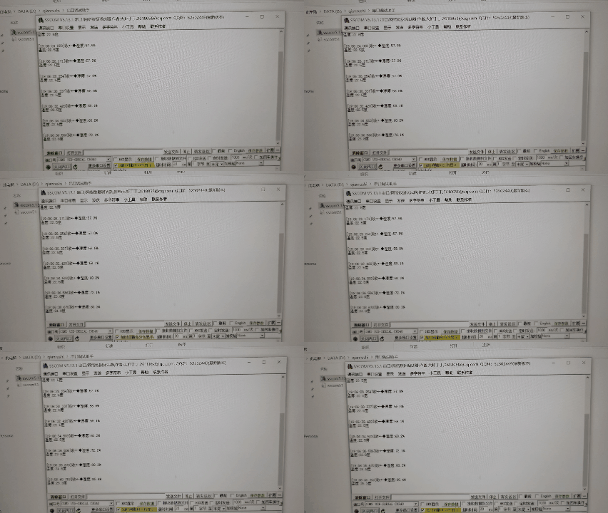
The picture shows that the indoor temperature is 22.5 and the humidity is 59.1%. When holding the sensor by hand, the temperature rises gradually.
3, Use of OLED lamps
1. Extract font using PCtoLCD2002
a. The software can be searched, downloaded and installed on the Internet, which is very simple.
b. In order to display Chinese characters correctly on the OLED display screen after compilation, the software needs to be set as follows.
Click the option in the software to make the following settings
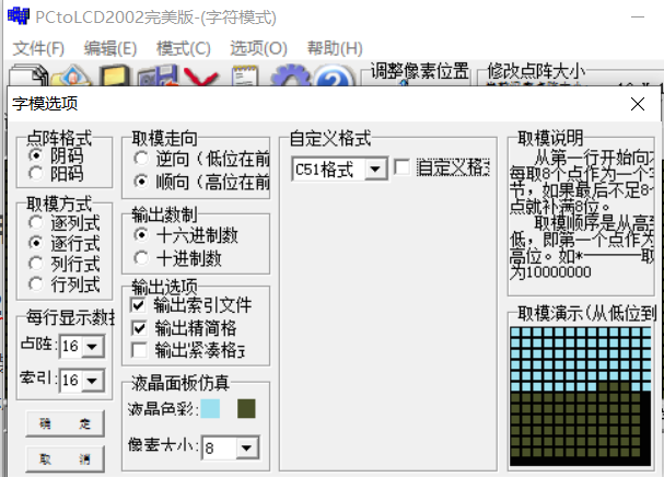
c. About the use of software
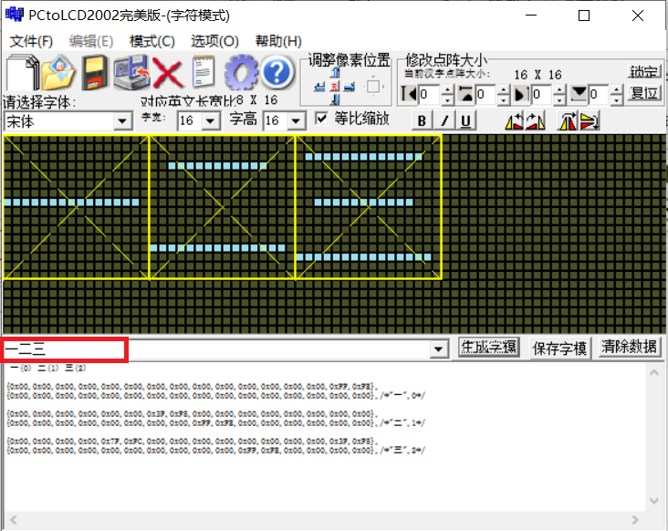
Enter the desired Chinese character in the red box and select generate font on the left. The content below is the generated font, which can be copied and pasted directly.
2. Code display name
1. Complete code
2. Relevant modifications
Put the above font into the specified location in the oledfont.h file as follows:

Here, the font is set, and then the text to be displayed is set in the test.c file, as follows:

The text here needs to take the font and write it in the program before it can be used.
When you get here, you can actually compile and burn.
Then introduce the meaning of some parameters
- GUI_ In showstring, the front 0 and 16 represent X and Y coordinates respectively. The class content in the quotation marks represents the displayed content (this function can only use characters), and the following 16 and 1 represent the character display format and display style respectively (1: white word with black background, 0: sunspot with white background)
- CUI_ In showChinese, the first two are coordinates, the third is the size of Chinese character dot matrix, then the Chinese character to be displayed, and finally the display format (ibid.).
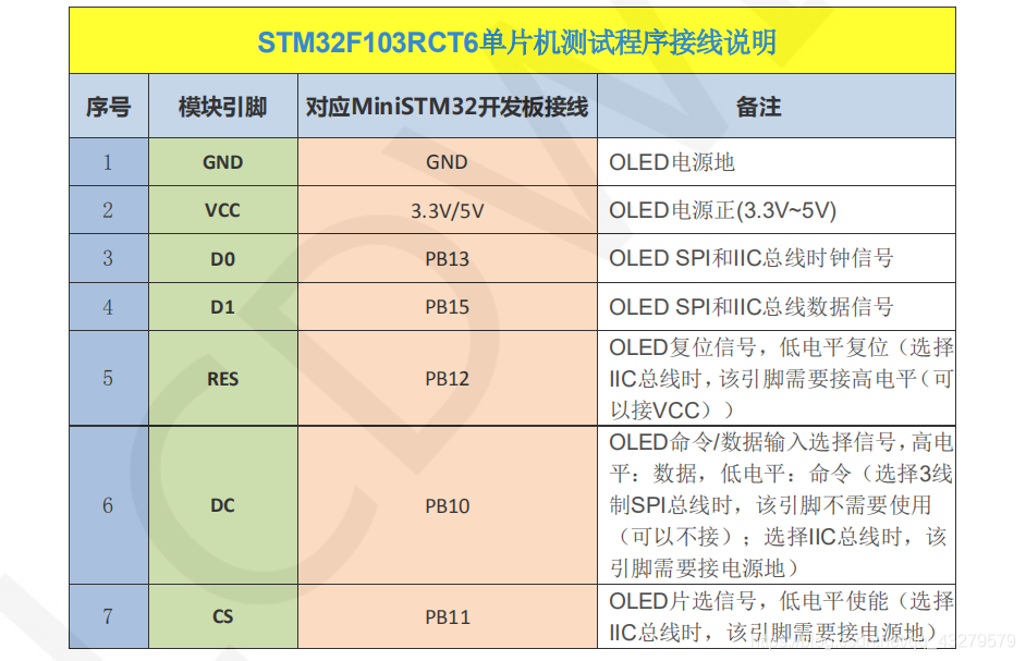
3.OLED connection method.
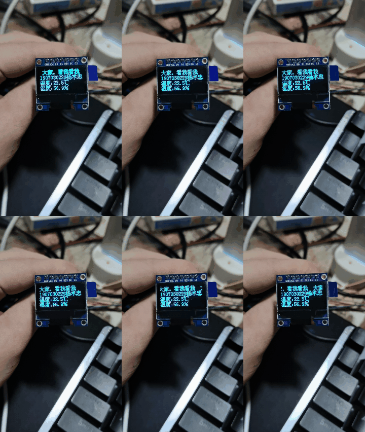
3. Effect display
4, Summary
I still have a sense of achievement, although I only made small changes. But I finally saw the effect of the code. Unlike the previous simulation, the feeling is empty. Although it is said to be learning, I feel that these agreements have been read, but I just can't understand them. The project is still very big, but I only read those codes. The whole project still has great research value and can be further studied.
Full code:
Link: https://pan.baidu.com/s/1brOj8G_eJVAxk21IVe3ofg
Extraction code: 4455
Reference link:
https://blog.csdn.net/ssj925319/article/details/111588662
https://blog.csdn.net/qq_43279579/article/details/111597278