Hardware:
(1) : 0.96 inch oled display
(2):stm32 development board can be used without interface. It can be plugged in with DuPont line
Objective:
We will use the OLED module interface on the elite STM32 development board (to light OLED and realize the display of ASCII characters.
principle
LCD needs backlight, but OLED doesn't, because it's self luminous.
OLED has a variety of lighting modes, including:
(1) : 6800 parallel interface mode
(2) : 8080 parallel interface mode
(3) : three wire spi interface mode
(4) : four wire spi interface mode
(5):IIC interface mode (only 2 wires are needed to control OLED!)
How do you set these five modes? There are some resistances on the back of the module. BS0 and BS1 are in the control mode. If you want to change the mode, you need to weld the resistance at the corresponding position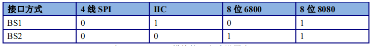
Of course, some partners are not such OLEDs, and my module is not 0.96 oled of punctual atom. I define the pin to control it! You can modify the mode according to the data manual provided by the manufacturer. The principle is almost the same!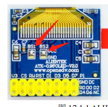
Here comes the point (four line spi)
It is very important to write OLED program well, understand the principle, process, direction and method of data writing, etc., rather than memorize the standard program by rote! Here is my understanding of the OLED I use:
Pin description
CS: OLED chip selection signal.
RST(RES): hard reset OLED.
DC: command / data flag (0, read-write command; 1, read-write data).
SCLK: serial clock line, D0 signal line as serial clock line
SDIN: serial data line, D1 signal line as serial data line
VCC and GND are also necessary, so they are 7-pin OLED modules
IO port configuration is relatively simple: the configured pins can also be seen
void oled_init(void)
{
	GPIO_InitTypeDef GPIO_InitStructure;
	RCC_APB2PeriphClockCmd(RCC_APB2Periph_GPIOC|RCC_APB2Periph_GPIOD|RCC_APB2Periph_GPIOD|RCC_APB2Periph_GPIOD|RCC_APB2Periph_GPIOG, ENABLE);
	GPIO_InitStructure.GPIO_Speed=GPIO_Speed_50MHz;
	GPIO_InitStructure.GPIO_Mode=GPIO_Mode_Out_PP;
	GPIO_InitStructure.GPIO_Pin=GPIO_Pin_3|GPIO_Pin_6;
	GPIO_Init(GPIOD,&GPIO_InitStructure);
	GPIO_SetBits(GPIOD,GPIO_Pin_3|GPIO_Pin_6);
	GPIO_InitStructure.GPIO_Pin=GPIO_Pin_1|GPIO_Pin_0;
	GPIO_Init(GPIOC,&GPIO_InitStructure);
	GPIO_SetBits(GPIOC,GPIO_Pin_1|GPIO_Pin_0);

	GPIO_InitStructure.GPIO_Pin=GPIO_Pin_15;
	GPIO_Init(GPIOG,&GPIO_InitStructure);
	GPIO_SetBits(GPIOG,GPIO_Pin_15);
	//oled¸´Î»
	OLED_RST=0;
	delay_ms(100);
	OLED_RST=1;
	//oled³õʼ»¯
	oled_writebyte(0xAE,OLED_CMD);
	oled_writebyte(0xD5,OLED_CMD);
	oled_writebyte(0x80,OLED_CMD);
	oled_writebyte(0xA8,OLED_CMD);
	oled_writebyte(0X3F,OLED_CMD);
	oled_writebyte(0xD3,OLED_CMD);
	oled_writebyte(0X00,OLED_CMD);
	oled_writebyte(0x40,OLED_CMD);
	oled_writebyte(0x8D,OLED_CMD);
	oled_writebyte(0x14,OLED_CMD);
	oled_writebyte(0x20,OLED_CMD);
	oled_writebyte(0x02,OLED_CMD);
	oled_writebyte(0xC8,OLED_CMD);
	oled_writebyte(0xA1,OLED_CMD);
	oled_writebyte(0xDA,OLED_CMD);
	oled_writebyte(0x12,OLED_CMD);
	oled_writebyte(0x81,OLED_CMD);
	oled_writebyte(0xEF,OLED_CMD);
	oled_writebyte(0xD9,OLED_CMD);
	oled_writebyte(0xf1,OLED_CMD);
	oled_writebyte(0xDB,OLED_CMD);
	oled_writebyte(0x30,OLED_CMD);
	oled_writebyte(0xA4,OLED_CMD);
	oled_writebyte(0xA6,OLED_CMD);
	oled_writebyte(0xAF,OLED_CMD);
	OLED_Clear();
}
As shown in the picture: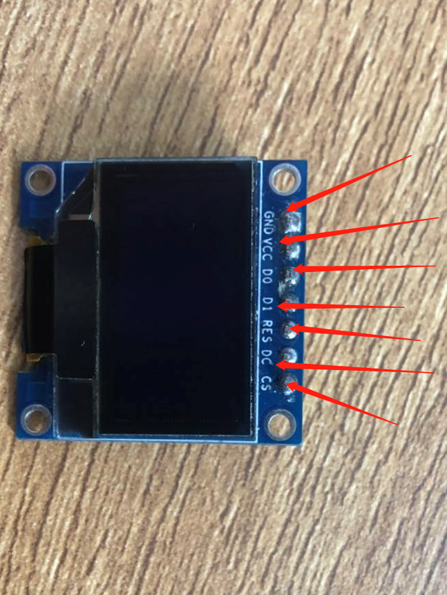
In 4-wire SPI mode, each data length is 8 bits. At the rising edge of SCLK, the data is moved from SDIN to SSD1306 of oled module, and the data is high in the front. The DC line is also used as a flag line for command / data.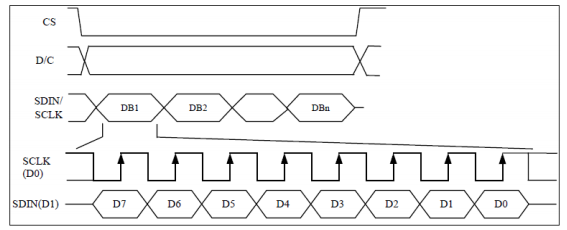
Dictate the timing of transmitting one byte from 32 to module SSD1306:
The data to be written is divided into command and data. Pull down the slice selection bit. At the beginning of data transmission, pull down the clock, take out the highest bit of the transmission byte, and pull up the clock. At this time, 1 bit of data is successfully written into SSD1306, and then one byte can be written after eight cycles. At this time, pull up the slice selection.
void oled_writebyte(unsigned char data,unsigned char oled_RS)
{
	int i;
	OLED_CS=0;//Chip selection low
	OLED_RS=oled_RS;//Data sent or command
	for(i=0;i<8;i++)
	{
		OLED_SCLK=0;
			if(data&0x80)
				OLED_SDIN=1;//Data bits
			else
				OLED_SDIN=0;//Data bits

			data<<=1;//Move Subhigh to highest
			OLED_SCLK=1;	//Clock pull up
	}
	OLED_CS=1;//Chip lift
	OLED_RS=1;
}
The data written to SSD1306 is divided into data and command. The written command is used to set the display parameters of OLED and the written data is used to display. Therefore:
(1) : understand the command to write and initialize the oled module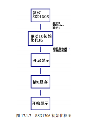
The initialization process can be verified according to this process!
(2) How to write the displayed data, how to display it in the display screen, the actual direction, size and so on are all very important
The second point begins:
One byte of data is written,
**If it's a command: * * we don't need to worry about how to arrange it in the module, because it won't affect our display,
If it's data: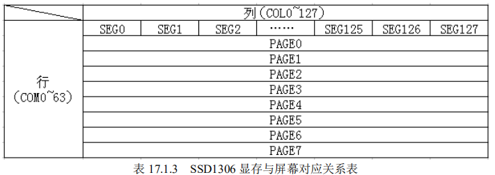
This is the relation table of the data we write to the corresponding screen. PAGE0 contains 128 bytes, i.e. 1288 pixels. There are eight pixels from PAGE0 to Page7, i.e. 1288 * 8 pixels. We take PAGE0,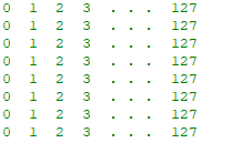
The above data only represents the number, not the real data. Eight bits of the same number constitute a byte. This byte is the display data of a byte that we write. What rule does this follow?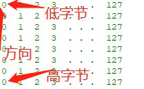
It can be seen from the writing sequence that the high byte is written first, then the low byte is written, so the direction of data writing is as shown in the figure. The total direction is: from bottom to top, from left to right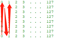
The internal structure of the bytes written is clear. Before that, we set the position to display this byte (one byte controls eight pixel points from top to bottom, which we should not know in detail). The figure above is just our PAGE0, So we need to make sure to write data on that PAGE. There is also a position from left to right for each PAGE. So write data, these are two parameters that must be written. Each PAGE only needs to be configured once. How to better control the data points written?
You can define a two-dimensional array of screen pixel size locally (yourself), eg: char a[128][8]
unsigned char GRAM[128][8];//128 * 8 bytes = 128 * 8 * 8 pixels
When our data point configuration (local two-dimensional array) is finished, we will send (refresh) to SSD1306 together, and we can use one pixel to piece together any graph we want!
void GRAM_REFRESH(void)
{
	int i;
	int j;
	for(i=0;i<8;i++)//8 page cycles 8 times
	{
		oled_writebyte(0xb0+i,OLED_CMD);//Page address, add 1 at a time
		oled_writebyte(0x00,OLED_CMD);//Start column address lower four bits when displayed
		oled_writebyte(0x10,OLED_CMD);//The top four digits of the starting column address when displaying
		for(j=0;j<128;j++)//Write one byte from bottom to top in 128 cycles
		{
			oled_writebyte(GRAM[j][i],OLED_DATA);
		}
	}
}
Basically achieved oled lighting
Small advanced (display single character)
Or a principle: for any displayed information, you can modify the local (self-defined two-dimensional array) first, and write the SSD1306 together (refresh) after the modification, so how to display the characters?
We are going to use the character set lattice now. The character set lattice is big or small, that is, to control the font size. A certain character is displayed in the fixed size area. The character lattice set can be synthesized by software, or copied by the small partners around you. It is a const type constant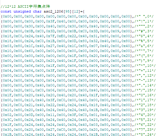
The above is the 1206 size dot matrix character set. There are too many codes, so it's inconvenient to code. If we want to use this size font to display the '!', that is, the second line of the above figure. 1206 means the size display plane composed of pixels 12 in height and 6 in width. One byte by byte is written. Now, one byte is regarded as a whole, and the direction is from top to bottom, from left to right, If one bit of a byte is taken as a whole, it is what we described earlier.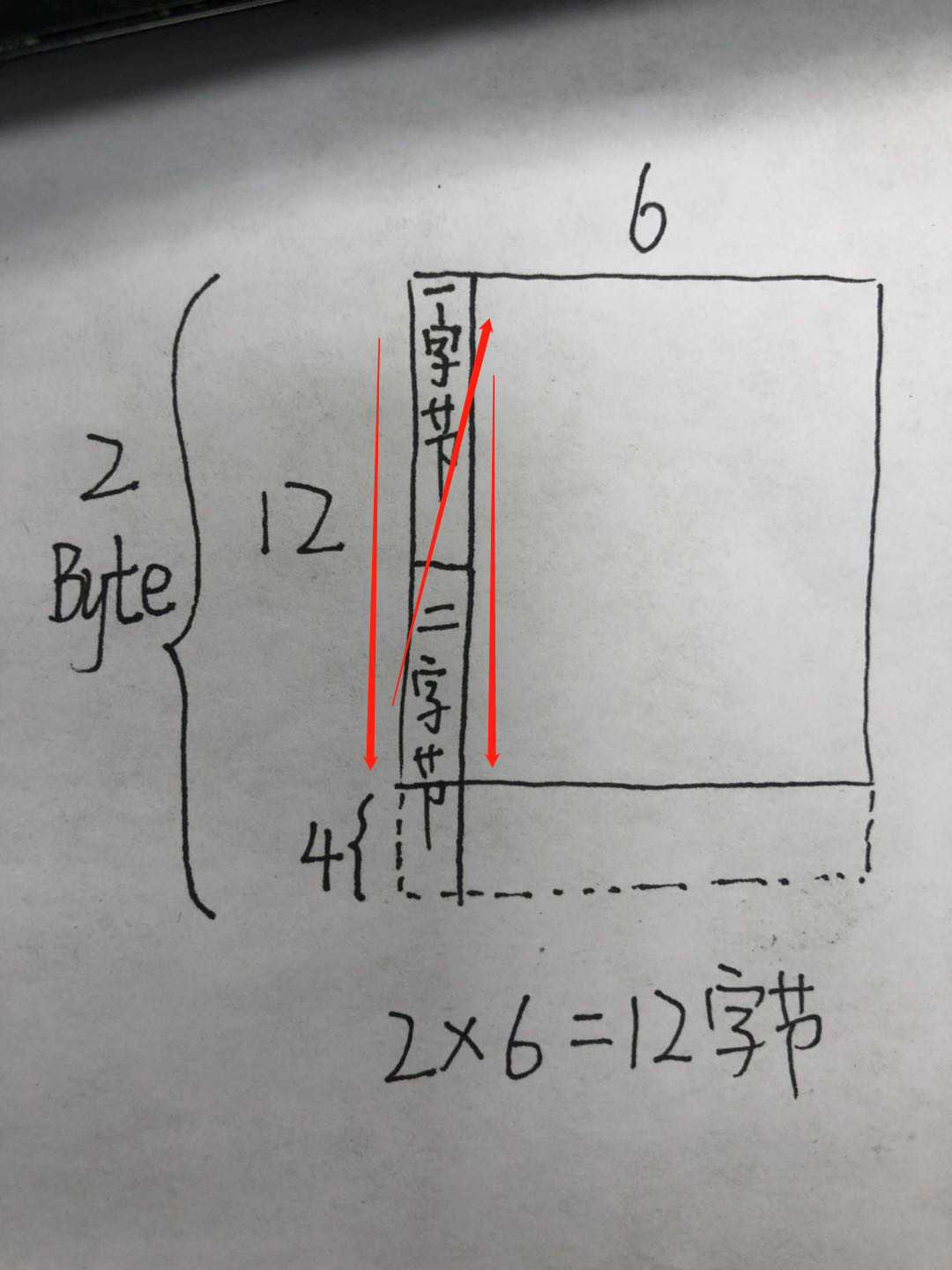
The dotted line part 4bit is the unwritten bit, which is discarded. This size takes up a total of 12 bytes, exactly corresponding to the 12 data on the dot matrix character set,
Very important function
void draw_char(unsigned char x,unsigned char y,unsigned char chr,unsigned char size)
{
	unsigned char csize;
	unsigned char num1;
	unsigned char num2;
	unsigned char data;
	unsigned char num3=y;
	unsigned char chr1;
	csize= (size/8+((size%8)?1:0))*(size/2);//Determine the number of pages the font occupies
	chr1=chr-' ';	//Get the offset value because the first character of the dot matrix character set is empty ''
	for(num1=0;num1<csize;num1++)
	{
		if(size==12)
		{data=asc2_1206[chr1][num1];}//1206 font
		else if(size==16)
			{data=asc2_1608[chr1][num1];}//1608 font
		else if(size==24)
				{data=asc2_2412[chr1][num1];}//2412 font
		else
			return ;
		for(num2=0;num2<8;num2++)
		{
					if(data&0x80)
				{
					draw_point(x,y);
				}
				else
				{
					clean_point(x,y);
				}
				data<<=1;
				y++;
				if((y-num3)==size)
				{
					y=num3;
					x++;
					break;
				}
		}
	}
}
This function has arranged the local two-dimensional array according to the characters. If you want to display the character 0 in the position of (20, 20) with 12 fonts, you can use this function
draw_char(20,20,'0',12);
Of course, if you want to use this function to display strings, in addition to the artificial large interval method (write another character far away from the next single character), you can pieced together the strings displayed on the display screen, and of course, there are also ways to display strings:
Advanced 1 (display string)
At this time, we use the pointer you like, and also use the above draw Chu char(); function. Here I provide you with two algorithms:
(1):
void draw_string(unsigned char x,unsigned char y, char* a,unsigned char size)
{
	unsigned char X,i;
	X=x;
	for(;*a!='\0';a++)
	{
		draw_char(x,y,*a,size);
		x+=size/2;
		if(x+size>128) //This line can no longer hold more characters, line feed
		{
			x=X;//The same x start bit as the previous string
			y+=size;//y add a font height to the display
    }
  }
}
In the draw char parameter, characters are passed in. Here we should pay attention to that we can cycle to judge whether the passed in string is a string end character '\ 0' as the flag bit
(2) : 95 characters are used to judge that there are characters between / "", 0 / < A + I < / "~", 94 * /
void draw_string(unsigned char x,unsigned char y, char* a,unsigned char size)
{
	while((*a>=' ')&&(*a<='~'))//Determine whether the character is one of the 95 characters
	{
		draw_char(x,y,*a,size);
		x+=size/2;
		if(x+size>127)
		{
			x=X;
			y+=size;
    }
		a++;
  }
}
If you want to display text, you can create it by dot matrix character making software and explore it by yourself!
The effect is as follows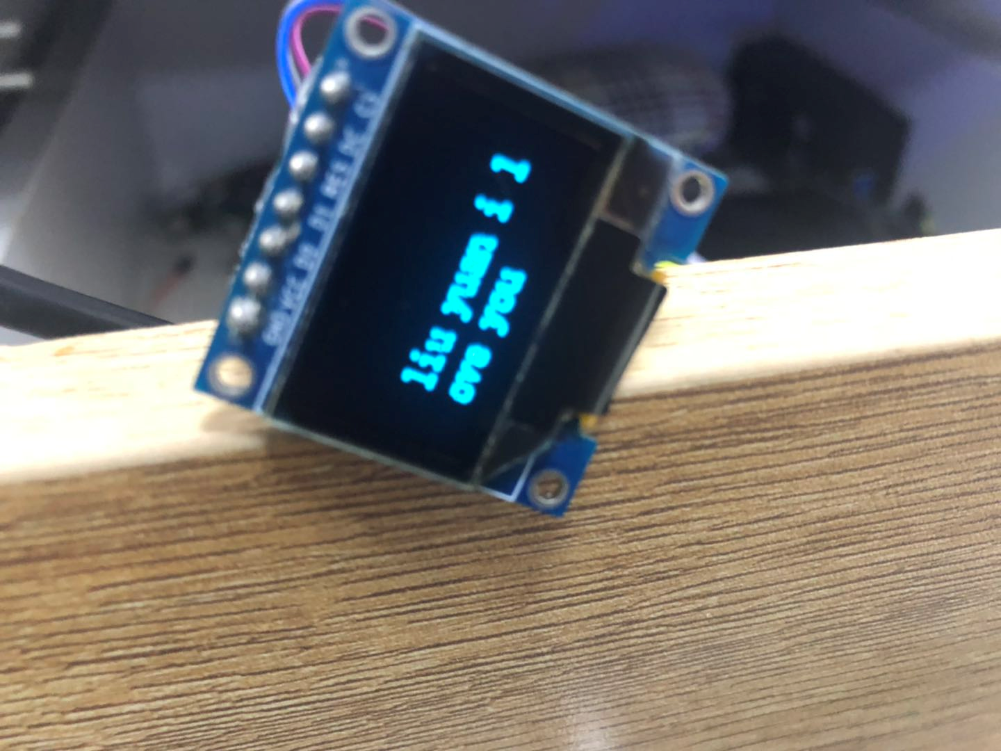
Advanced 2 (display line)
I believe that the previous process can be completed, and the display line should also be able to be completed. Code directly, and you should be able to understand:
void draw_line(unsigned char x1,unsigned char y1,unsigned char x2,unsigned char y2 )
{
	unsigned  char k1,k2,i,k;
	if(x1==x2)//Draw vertical lines
	{
		if(y1>y2)
		{
				for(y2;y2<=y1;y2++)
			{
					draw_point(x2,y2);
			}
		}
		else
		{
			for(y1;y1<=y2;y1++)
			{
					draw_point(x1,y1);
			}
		}
	}
	else if(y1==y2)   //Draw horizontal line
	{

			for(i=0;i<=(x2-x1);i++)
			{
				draw_point(x1+i,y1);
			}
  }
	else if(x1!=x2&&y1!=y2)//Draw oblique lines
	{
		k1=y2-y1;
		k2=x2-x1;
		k=k1*10/k2;
		for(i=0;i<(x2-x1);i++)
			{
			  draw_point(x1+i,y1+i*k/10);
			}
  }
}
Parameters x1,y1,x2,y2 are the coordinates of two points of the straight line;
Do not forget the refresh function at the end, otherwise there is no display
Here, I just provide algorithms and ideas. There are too many codes. I hope they will be useful to readers. Understand the principles. Refer to the data book. Other OLEDs are not a problem. You must understand the principles before you read the code. Otherwise, you will get twice the result!
There are display circles, pictures and so on, the principle is the same, I hope we must practice!
This blog is only for writing, not for reading. There is still a lot of room to expand. Thank you, and I hope readers can give me better suggestions and learn from each other

