1. First, find a blank project template, create two folders (groups) in the project: Radio and platform, add to the platform, FIFO. C, led. C, sx1276 Hal. C, sx12xxeiger. C; add radio. C, sx1276 FSK. C, sx1276 fskmisc. C, sx1276 loramisc. C, sx1276 loramisc. C, sx1276. C; and add the corresponding header file path in the project. Compile the whole project with errors.
2. The first modification is to add the macro definition PLATFORM=SX12xxEiger to the development software. This macro definition is called at the beginning of the platform.h file for conditional compilation.
3. The header file stm32f10x h cannot be found. Here we modify the macro definition at the beginning of sx12xeiger. H and fifo.h, as shown in Figure 1. Because I use platform 103, I modify it according to the requirements.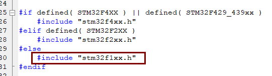
Figure 1 modification including header change file
3. The code that cannot be used in the annotation part can be modified according to the platform, and can be used for entry-level learning. Comment the following code in sx12xxEiger.c.
//#if( defined( STM32F4XX ) || defined( STM32F2XX ) || defined( STM32F429_439xx ) )
//
//#include "usbd_cdc_core.h"
//#include "usbd_usr.h"
//#include "usbd_desc.h"
//
//#else
//
//#include "usb_regs.h"
//#include "usb_core.h"
//#include "usb_init.h"
//#include "usb_pwr.h"
//#include "usb_bsp.h"
//#include "usb_sil.h"
//
//#endif

//#if( defined( STM32F4XX ) || defined( STM32F2XX ) || defined( STM32F429_439xx ) )
//
//#ifdef USB_OTG_HS_INTERNAL_DMA_ENABLED
//  #if defined ( __ICCARM__ ) /*!< IAR Compiler */
//    #pragma data_alignment=4
//  #endif
//#endif /* USB_OTG_HS_INTERNAL_DMA_ENABLED */
//
//__ALIGN_BEGIN USB_OTG_CORE_HANDLE    USB_OTG_dev __ALIGN_END ;
//
//#else
//
//#endif
Annotate all the code in the void BoardInit (void) function, taking care not to annotate the function name. Because I use the HAL library configured with Cube MX, I don't need to initialize it, and the sx1276 driver source code is written on the standard library functions.
4. Modify led related content. First, modify the definition of IO port in the led.h file. We don't care about other platforms in conditional compilation. We only care about those in else. The changes are as follows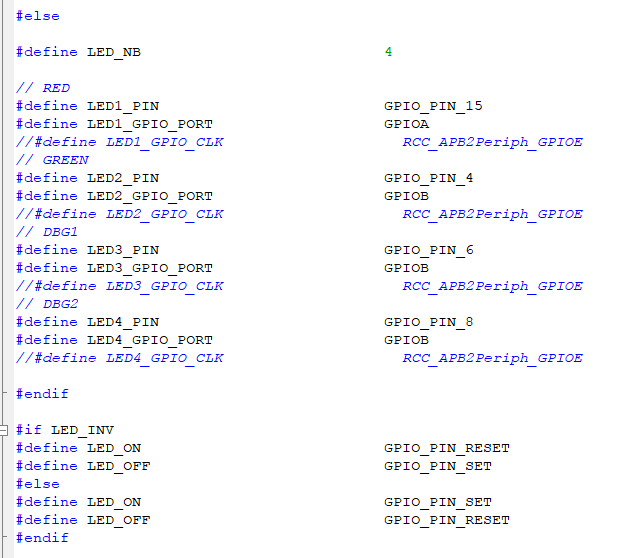
Figure 2 LED port modification
Next, modify the clock and initialization in led.c. note the internal code of void ledinit (tled LED) directly without using the clock, as shown in Figure 3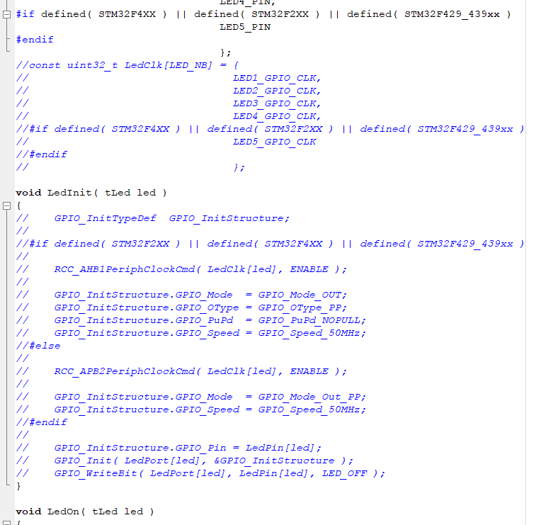
Figure 3 led initialization modification
Replace the standard library inside void ledon (TLAD LED) and void ledoff (TLAD LED) with HAL library function code as follows
void LedOn( tLed led )
{
    HAL_GPIO_WritePin( LedPort[led], LedPin[led], LED_ON );
}

void LedOff( tLed led )
{
    HAL_GPIO_WritePin( LedPort[led], LedPin[led], LED_OFF );
}
5. Modify the sx1276-Hal.c file.
Modify reset, NSS, DIO0 to DIO5 according to my own platform. Here, I use hardware reset to directly comment out. DIO uses 0 to 3, and the rest are commented out. Please note that only the port under conditional compilation is concerned. The code is as follows
/*!
 * SX1276 SPI NSS I/O definitions
 */
#if defined( STM32F4XX ) || defined( STM32F2XX )
#define NSS_IOPORT                                  GPIOA
#define NSS_PIN                                     GPIO_Pin_15
#elif defined( STM32F429_439xx )
#define NSS_IOPORT                                  GPIOA
#define NSS_PIN                                     GPIO_Pin_4
#else
#define NSS_IOPORT                                  GPIOC
#define NSS_PIN                                     GPIO_PIN_4
#endif

/*!
 * SX1276 DIO pins  I/O definitions
 */
#if defined( STM32F4XX ) || defined( STM32F2XX )
#define DIO0_IOPORT                                 GPIOG
#define DIO0_PIN                                    GPIO_Pin_13
#elif defined( STM32F429_439xx )
#define DIO0_IOPORT                                 GPIOG
#define DIO0_PIN                                    GPIO_Pin_13
#else
#define DIO0_IOPORT                                 GPIOB
#define DIO0_PIN                                    GPIO_PIN_12
#endif

#if defined( STM32F4XX ) || defined( STM32F2XX )
#define DIO1_IOPORT                                 GPIOB
#define DIO1_PIN                                    GPIO_Pin_8
#elif defined( STM32F429_439xx )
#define DIO1_IOPORT                                 GPIOB
#define DIO1_PIN                                    GPIO_Pin_7
#else
#define DIO1_IOPORT                                 GPIOB
#define DIO1_PIN                                    GPIO_PIN_13
#endif

#if defined( STM32F4XX ) || defined( STM32F2XX )
#define DIO2_IOPORT                                 GPIOA
#define DIO2_PIN                                    GPIO_Pin_2
#elif defined( STM32F429_439xx )
#define DIO2_IOPORT                                 GPIOA
#define DIO2_PIN                                    GPIO_Pin_2
#else
#define DIO2_IOPORT                                 GPIOB
#define DIO2_PIN                                    GPIO_PIN_14
#endif

//#if defined( STM32F4XX ) || defined( STM32F2XX ) || defined( STM32F429_439xx )
//#define DIO3_IOPORT
//#define DIO3_PIN                                    RF_DIO3_PIN
//#else
//#define DIO3_IOPORT                                 GPIOB
//#define DIO3_PIN                                    GPIO_PIN_15
//#endif
//
//#if defined( STM32F4XX ) || defined( STM32F2XX ) || defined( STM32F429_439xx )
//#define DIO4_IOPORT
//#define DIO4_PIN                                    RF_DIO4_PIN
//#else
//#define DIO4_IOPORT
//#define DIO4_PIN                                    RF_DIO4_PIN
//#endif
//
//#if defined( STM32F4XX ) || defined( STM32F2XX ) || defined( STM32F429_439xx )
//#define DIO5_IOPORT
//#define DIO5_PIN                                    RF_DIO5_PIN
//#else
//#define DIO5_IOPORT
//#define DIO5_PIN                                    RF_DIO5_PIN
//#endif
//
//#if defined( STM32F4XX ) || defined( STM32F2XX ) || defined( STM32F429_439xx )
//#define RXTX_IOPORT
//#define RXTX_PIN                                    FEM_CTX_PIN
//#else
//#define RXTX_IOPORT
//#define RXTX_PIN                                    FEM_CTX_PIN
//#endif


void SX1276InitIo( void )
{
//    GPIO_InitTypeDef GPIO_InitStructure;
//
//#if defined( STM32F4XX ) || defined( STM32F2XX ) || defined( STM32F429_439xx )
//    RCC_AHB1PeriphClockCmd( RCC_AHB1Periph_GPIOA | RCC_AHB1Periph_GPIOB |
//                            RCC_AHB1Periph_GPIOG, ENABLE );
//#else
//    RCC_APB2PeriphClockCmd( RCC_APB2Periph_GPIOA | RCC_APB2Periph_GPIOB |
//                            RCC_APB2Periph_GPIOC | RCC_APB2Periph_AFIO, ENABLE );
//#endif
//
//#if defined( STM32F4XX ) || defined( STM32F2XX ) || defined( STM32F429_439xx )
//    GPIO_InitStructure.GPIO_Mode = GPIO_Mode_OUT;
//    GPIO_InitStructure.GPIO_Speed = GPIO_Speed_50MHz;
//    GPIO_InitStructure.GPIO_OType = GPIO_OType_PP;
//    GPIO_InitStructure.GPIO_PuPd  = GPIO_PuPd_UP;
//#else
//    GPIO_InitStructure.GPIO_Mode  = GPIO_Mode_Out_PP;
//    GPIO_InitStructure.GPIO_Speed = GPIO_Speed_50MHz;
//#endif
//
//    // Configure NSS as output
//    GPIO_WriteBit( NSS_IOPORT, NSS_PIN, Bit_SET );
//    GPIO_InitStructure.GPIO_Pin = NSS_PIN;
//    GPIO_Init( NSS_IOPORT, &GPIO_InitStructure );
//
//    // Configure radio DIO as inputs
//#if defined( STM32F4XX ) || defined( STM32F2XX ) || defined( STM32F429_439xx )
//    GPIO_InitStructure.GPIO_Mode = GPIO_Mode_IN;
//    GPIO_InitStructure.GPIO_Speed = GPIO_Speed_50MHz;
//#else
//    GPIO_InitStructure.GPIO_Mode = GPIO_Mode_IN_FLOATING;
//#endif
//
//    // Configure DIO0
//    GPIO_InitStructure.GPIO_Pin =  DIO0_PIN;
//    GPIO_Init( DIO0_IOPORT, &GPIO_InitStructure );
//
//    // Configure DIO1
//    GPIO_InitStructure.GPIO_Pin =  DIO1_PIN;
//    GPIO_Init( DIO1_IOPORT, &GPIO_InitStructure );
//
//    // Configure DIO2
//    GPIO_InitStructure.GPIO_Pin =  DIO2_PIN;
//    GPIO_Init( DIO2_IOPORT, &GPIO_InitStructure );
//
//    // REAMARK: DIO3/4/5 configured are connected to IO expander
//
//    // Configure DIO3 as input
//
//    // Configure DIO4 as input
//
//    // Configure DIO5 as input
}

void SX1276SetReset( uint8_t state )
{
//    GPIO_InitTypeDef GPIO_InitStructure;

    if( state == RADIO_RESET_ON )
    {
        // Set RESET pin to 0
        HAL_GPIO_WritePin( RESET_IOPORT, RESET_PIN, GPIO_PIN_RESET );

        // Configure RESET as output
//#if defined( STM32F4XX ) || defined( STM32F2XX ) || defined( STM32F429_439xx )
//        GPIO_InitStructure.GPIO_Mode = GPIO_Mode_OUT;
//        GPIO_InitStructure.GPIO_OType = GPIO_OType_PP;
//#else
//
//        GPIO_InitStructure.GPIO_Mode  = GPIO_Mode_Out_PP;
//#endif
//        GPIO_InitStructure.GPIO_Speed = GPIO_Speed_50MHz;
//        GPIO_InitStructure.GPIO_Pin = RESET_PIN;
//        GPIO_Init( RESET_IOPORT, &GPIO_InitStructure );
    }
    else
    {
//#if FPGA == 0
//        // Configure RESET as input
//#if defined( STM32F4XX ) || defined( STM32F2XX ) || defined( STM32F429_439xx )
//        GPIO_InitStructure.GPIO_Mode = GPIO_Mode_IN;
//#else
//        GPIO_InitStructure.GPIO_Mode = GPIO_Mode_IN_FLOATING;
//#endif
//        GPIO_InitStructure.GPIO_Speed = GPIO_Speed_50MHz;
//        GPIO_InitStructure.GPIO_Pin =  RESET_PIN;
//        GPIO_Init( RESET_IOPORT, &GPIO_InitStructure );
//#else
        HAL_GPIO_WritePin( RESET_IOPORT, RESET_PIN, GPIO_PIN_RESET );
//#endif
    }
}
Note that the following read-write Buffer needs to be changed to HAL library function. The code is as follows
void SX1276WriteBuffer( uint8_t addr, uint8_t *buffer, uint8_t size )
{
    uint8_t i;

    //NSS = 0;
    HAL_GPIO_WritePin( NSS_IOPORT, NSS_PIN, GPIO_PIN_RESET );

    SpiInOut( addr | 0x80 );
    for( i = 0; i < size; i++ )
    {
        SpiInOut( buffer[i] );
    }

    //NSS = 1;
    HAL_GPIO_WritePin( NSS_IOPORT, NSS_PIN, GPIO_PIN_SET );
}

void SX1276ReadBuffer( uint8_t addr, uint8_t *buffer, uint8_t size )
{
    uint8_t i;

    //NSS = 0;
    HAL_GPIO_WritePin( NSS_IOPORT, NSS_PIN, GPIO_PIN_RESET );

    SpiInOut( addr & 0x7F );

    for( i = 0; i < size; i++ )
    {
        buffer[i] = SpiInOut( 0 );
    }

    //NSS = 1;
    HAL_GPIO_WritePin( NSS_IOPORT, NSS_PIN, GPIO_PIN_SET );
}
Change the return value of the unused DIO read function to 1 to prevent errors. Note out the following hardware control transceiver.
6. Modify the tick in sx1276-Hal.h to get the macro definition, and use the HAL library function. The code is as follows
#define GET_TICK_COUNT( ) ( HAL_GetTick() )
7 implement uint8 ﹣ t spiinout (uint8 ﹣ t outdata) function
We write the implementation functions in SPI related files, such as spi.c. The code is as follows
uint8_t SpiInOut( uint8_t outData )
{
  uint8_t pData = 0;
  if(HAL_SPI_TransmitReceive(&hspi1, &outData, &pData, 1, 0xffff)!= HAL_OK)
    return ERROR;
  else
    return pData;
}
8. Power on self check operation, which proves that the transplantation is successful
Add the following code in the main function initialization, and pay attention to the introduction of related header files.
SX1276Read( REG_LR_VERSION, &RegVersion );
  if(RegVersion != 0x12)
  {
    printf("LoRa Read Error!!!\r\n");
    printf("LoRa RegVersion: %#x\r\n", RegVersion);
    printf("Init Error!!!\r\n");
  }
  else
  {
    printf("LoRa Read OK!!!\r\n");
    printf("LoRa RegVersion: %#x\r\n", RegVersion);
    printf("Init Ok!!!\r\n");
    //LedToggle(LED_GREEN);
  }
At the end of this migration, the test is available. For more learning and communication, please join QQ group: 1095431780