NXP FS6500/FS4500 family power chip driver
1, General overview
1. Multi power output, linear power voltage regulator, switching power supply, automotive power chip supporting low power consumption and multiple wake-up mode capabilities and modes
2. Support 1-5v MCU power supply and SMPS (switching mode power supply) 0.8A,1.5A,2.2A linear regulator, support AD,IO,MCU, etc., and support 3.3v,5v auxiliary linear voltage monitoring.
3. A variety of safety fault monitoring and detection, feedback fault state safety protection.
4. It is applied to various BMS, automobile chassis electrical system, automobile power system and transmission system, etc.
5. 16 bit SPI communication, watchdog monitoring.
5. The functions of different belts of the series are also different. This time, FS4505C is used to support CANFD.
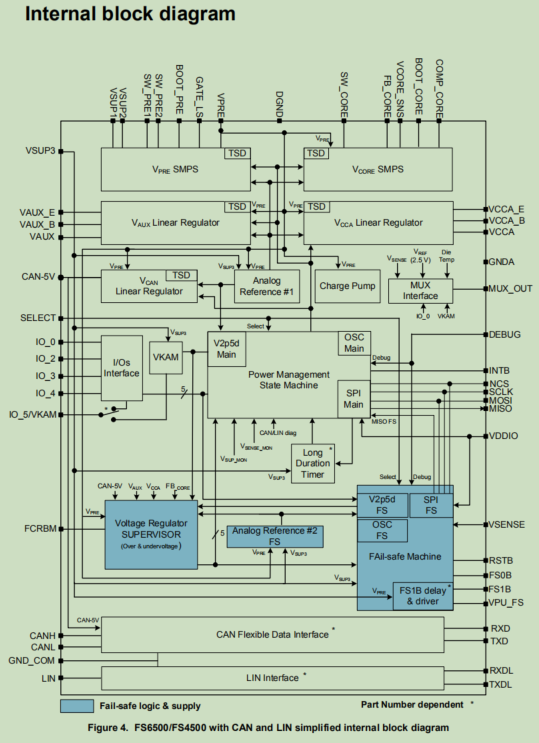
6. block diagram and pin map
2, Working mode
1. Functional state diagram, the working process of the chip is complex.
The chip generally involves:
1. Self inspection
2.IO configuration
3. Error safe machine (overvoltage and undervoltage) start and start after wake-up
4. Reset
5.INIT_FS
6.NORMAL WD feeding dog
7. Set the reset time
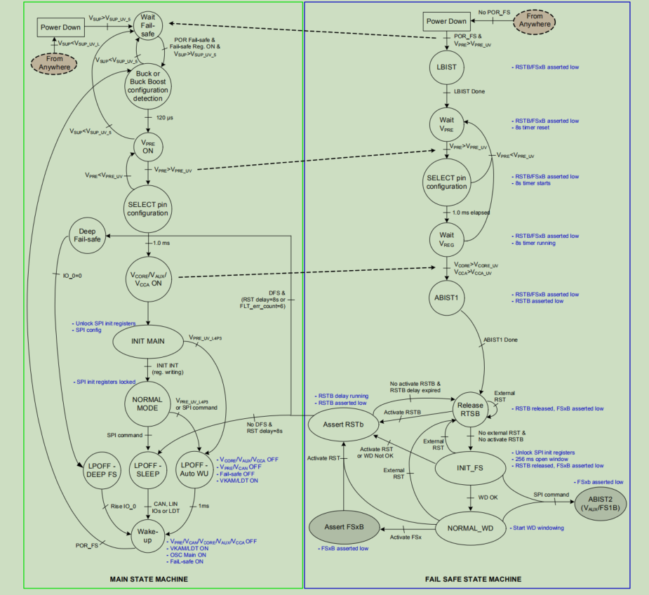
2, Fail-safe machine state diagram
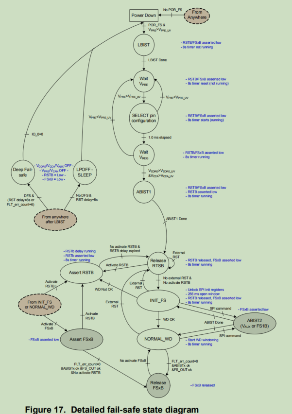
3. The main working modes are normal operation and fault state feedback, of which the more important is the feeding of the chip to the dog.
4. The dog feeding steps and monitoring of the chip are troublesome, and there are many registers involved.
The general dog feeding steps involve:
1.seed
2.LFSR
3.WD refresh counter
4.WD error counter
5. For debug exit, you need to be grounded first, and then power reset or wake-up reset.
6. If you fail to feed the dog, you will make a mistake.
7. Start debugging purpose and set the level of debug pin to suppress it.
8. Enter init after reset_ FS mode at this time, spi communication sets watchdog windows refresh. Some registers must be set at this time, otherwise, except for this mode, they will be locked directly. The register table is marked., Set the register before feeding the dog for the first time
9.3 low power modes, 1.sleep, all regulators are useless, only the spi command for security is useful, and there are three wake-up modes, 1.can/lin, 2.i/o input, and 3.timer.
3, Commissioning summary
1. Debug mode, on the premise of not knowing whether the power supply can feed the dog normally, we need to enter the debug mode, first start the power supply to supply power to the chip normally, and then the MCU works normally and can download the program. The debug mode requires a pull-up resistance of about 10K, which may be different for different hardware.
2. Ensure that SPI communication is normal, and ID can be read by measuring SPI signal. The SPI performs register configuration under normal communication.
3. First initialize the normal working mode of the chip, including all steps in the register structure and working mode.
FS65_RegVal_struct FS65_Registers_InitValues = {
    0x00,	//	INIT_VREG;
    0x40,	//	INIT_WU1;
    0x00,	//	INIT_WU2;->CAN sleep mode 0X20
    0x00,	//	INIT_INT;

    0x00,	//	INIT_INH_INT;
    0xE0,	//	CAN_LIN_MODE; CAN in Normal mode 0XF4 ->shut down lin TX 0xE0
    0x60,	//	INIT_FS1B_TIMING;
    0x00,	//	INIT_SUPERVISOR;

    0x10,	//	INIT_FAULT;

   // 0x4D,	//	INIT_FSSM: IO_23 is fail-safe
    0x00,	//	INIT_FSSM: IO_23 not fail-safe
    0x10,	//	INIT_SF_IMPACT;
	0xC0,	//	WD_WINDOW;0x0

    0xB2,	//	WD_LFSR;
    0x00,	//	INIT_WD_CNT;
    0xE0,	//	INIT_VCORE_OVUV_IMPACT;
    0xE0,	//	INIT_VCCA_OVUV_IMPACT;

    0xE0,	//	INIT_VAUX_OVUV_IMPACT;

};
void FS65_Init(void) {

uint32_t fs65_error_code;

// 0. Get silicon version
fs65_error_code = FS65_UpdateRegisterContent(DEVICE_ID_ADR);

// 1.Check LBIST & ABIST1 completion
fs65_error_code = FS65_UpdateRegisterContent(BIST_ADR);
if (fs65_error_code != FS65_RETURN_OK) {
FS65_Error = FS65_SPI_FAIL;
FS65_ErrorCallback();
}

if (INTstruct.BIST.B.LBIST_OK != 1) {
// LBIST Fail, FSx can not be released, user action required
FS65_Error = FS65_LBIST_FAIL;
FS65_ErrorCallback();
}
if (INTstruct.BIST.B.ABIST1_OK !=1) {
// ABIST1 Fail, FSx can not be relaesed, user action required
FS65_Error = FS65_ABIST1_FAIL;
FS65_ErrorCallback();
}

// 2. Get cause of SBC restart
fs65_error_code = FS65_UpdateRegisterContent(INIT_VREG_ADR);
if (fs65_error_code != FS65_RETURN_OK ) {
FS65_Error = FS65_SPI_FAIL;
FS65_ErrorCallback();
}

// 3. Power-On Reset, Init Main registers should be initialized
fs65_error_code = FS65_Init_MSM();
if (fs65_error_code != FS65_RETURN_OK) {
    // Error during initialization, user action required
    FS65_Error = FS65_INIT_MSM_FAIL;
    FS65_ErrorCallback();//ERROR
}


fs65_error_code = FS65_UpdateRegisterContent(WU_SOURCE_ADR); //Read and clear WU sources
if (fs65_error_code != FS65_RETURN_OK ) {
    FS65_Error = FS65_SPI_FAIL;
    FS65_ErrorCallback();
}

// 5. Init FSSM registers
fs65_error_code = FS65_Init_FSSM();
if (fs65_error_code != FS65_RETURN_OK) {
    // Error during initialization, user action required
FS65_Error = FS65_INIT_FSSM_FAIL;
FS65_ErrorCallback();
}

// 5bis; Get current mode of operation
fs65_error_code = FS65_UpdateRegisterContent(MODE_ADR);
if (fs65_error_code != FS65_RETURN_OK) {
    // Error during initialization, user action required
FS65_Error = FS65_INIT_FSSM_FAIL;
FS65_ErrorCallback();
}

// 5ter; Check HW configuration of Vaux/Vcca
fs65_error_code = FS65_UpdateRegisterContent(HW_CONFIG_ADR);
if (fs65_error_code != FS65_RETURN_OK) {
    // Error during initialization, user action required
FS65_Error = FS65_INIT_FSSM_FAIL;
FS65_ErrorCallback();
}

// 6. Read all Diag registers to clear all bits
fs65_error_code = FS65_RETURN_OK;
fs65_error_code += FS65_UpdateRegisterContent(DIAG_VPRE_ADR);
fs65_error_code += FS65_UpdateRegisterContent(DIAG_VCORE_ADR);
fs65_error_code += FS65_UpdateRegisterContent(DIAG_VCCA_ADR);
fs65_error_code += FS65_UpdateRegisterContent(DIAG_VAUX_ADR);
fs65_error_code += FS65_UpdateRegisterContent(DIAG_VSUP_VCAN_ADR);
fs65_error_code += FS65_UpdateRegisterContent(DIAG_CAN_FD_ADR);
fs65_error_code += FS65_UpdateRegisterContent(DIAG_CAN_LIN_ADR);
fs65_error_code += FS65_UpdateRegisterContent(DIAG_SPI_ADR);
fs65_error_code += FS65_UpdateRegisterContent(DIAG_SF_IOS_ADR);
fs65_error_code += FS65_UpdateRegisterContent(DIAG_SF_ERR_ADR);
if (fs65_error_code != FS65_RETURN_OK ) {
FS65_Error = FS65_SPI_FAIL;
FS65_ErrorCallback();
}

// 7. Check if FS1b implemented
fs65_error_code = FS65_UpdateRegisterContent(DEVICE_ID_FS_ADR);
if (fs65_error_code != FS65_RETURN_OK ) {
FS65_Error = FS65_SPI_FAIL;
FS65_ErrorCallback();
}

if (INTstruct.DEVICE_ID_FS.B.FS1 == 1)
{
//FS1B is implemented, it should be zero at this stage
fs65_error_code = FS65_UpdateRegisterContent(RELEASE_FSxB_ADR);
if (fs65_error_code != FS65_RETURN_OK ) {
    FS65_Error = FS65_SPI_FAIL;
    FS65_ErrorCallback();
}
//Read state of FS1B sense
if (INTstruct.RELEASE_FSxB.B.FS1B_SNS == 1)
{
    //FS1B already high
    //fs65_error_code = FS65_UpdateRegisterContent(DIAG_SF_IOS_ADR);
    if (fs65_error_code != FS65_RETURN_OK ) {
	FS65_Error = FS65_SPI_FAIL;
	FS65_ErrorCallback();
    }

    if (INTstruct.DIAG_SF_IOS.B.FS1B_DIAG >= 2)
    {
	//FS1b short-circuited to high, user action required
	FS65_Error = FS65_FS1B_SHORT2HIGH;
	FS65_ErrorCallback();
   }
    else
    {   //FS1B is still high because of the running delay, wait a little
	do {
	    fs65_error_code = FS65_UpdateRegisterContent(RELEASE_FSxB_ADR);
	    if (fs65_error_code != FS65_RETURN_OK ) {
		FS65_Error = FS65_SPI_FAIL;		FS65_ErrorCallback();
	    }
	}
	while (INTstruct.RELEASE_FSxB.B.FS1B_SNS == 1);
   }
}

//Run ABIST2_FS1B
fs65_error_code = FS65_RunABIST2_FS1B();
if (fs65_error_code != FS65_RETURN_OK) {
    // Error during ABIST2, user action required
    FS65_Error = FS65_ABIST2_FS1B_FAIL;
    FS65_ErrorCallback();
}
FUN_HW_Time_Delayus(200);

fs65_error_code = FS65_UpdateRegisterContent(BIST_ADR);
if (fs65_error_code != FS65_RETURN_OK ) {
    FS65_Error = FS65_SPI_FAIL;
    FS65_ErrorCallback();
}

if (INTstruct.BIST.B.ABIST2_FS1B_OK != 1) {
   // Error during ABIST2, user action required
   FS65_Error = FS65_ABIST2_FS1B_FAIL;
   FS65_ErrorCallback();
}
}

// 8. BIST Vaux if necessary
fs65_error_code = FS65_UpdateRegisterContent(INIT_VAUX_OVUV_IMPACT_ADR);
if (fs65_error_code != FS65_RETURN_OK ) {
FS65_Error = FS65_SPI_FAIL;
FS65_ErrorCallback();
}

if ((INTstruct.INIT_VAUX_OVUV_IMPACT.B.VAUX_FS_OV != 0) && (INTstruct.INIT_VAUX_OVUV_IMPACT.B.VAUX_FS_UV != 0))
{   // Vaux is safety critical, need to BIST it
//Run ABIST2_VAUX
fs65_error_code = FS65_RunABIST2_VAUX();
if (fs65_error_code != FS65_RETURN_OK) {
    // Error during ABIST2 VAUX, user action required
    FS65_Error = FS65_ABIST2_VAUX_FAIL;
    FS65_ErrorCallback();
}

FUN_HW_Time_Delayus(200);

fs65_error_code = FS65_UpdateRegisterContent(BIST_ADR);
if (fs65_error_code != FS65_RETURN_OK ) {
    FS65_Error = FS65_SPI_FAIL;
    FS65_ErrorCallback();
}

if (INTstruct.BIST.B.ABIST2_VAUX_OK != 1) {
    // Error during ABIST2 VAUX, user action required
    FS65_Error = FS65_ABIST2_VAUX_FAIL;
    FS65_ErrorCallback();
}

  }
}
4. For dog feeding, the chip will have a dog feeding time of 256ms window during initialization. The initialization needs to feed the dog once, and then enter the normal cycle to feed the dog.
void FS65_WD_Refresh(void){
    static uint32_t nbWDrefresh = 0;
    static uint32_t FSOUTreleased = 0;
    nbWDrefresh++;

    FS65_UpdateRegisterContent(WD_LFSR_ADR);		//get current LFSR content
    PITstruct.WD_answer = FS65_ComputeLFSR((INTstruct.WD_LFSR.R));
    FS65_RefreshWD((PITstruct.WD_answer));
    FS65_UpdateRegisterContent(DIAG_SF_ERR_ADR);
    FS65_UpdateRegisterContent(DIAG_SF_ERR_ADR);
    FS65_UpdateRegisterContent(WD_COUNTER_ADR);
    /*7th WD clear the FLT_ERR_CNT)*/
    if((FSOUTreleased == 0) & (nbWDrefresh >= 7)){
      FSOUTreleased = 1;
      FS65_ReleaseFS0andFS1out();
    }

//    PIT_0.TIMER[2].TFLG.R=1;
}
5. Wake up setting, IO signal wake-up, CAN wake-up, etc
uint32_t FS65_Config_NonInit(void)
{
    uint32_t errorCode = FS65_RETURN_OK;
    FS65_WD_Refresh();
	errorCode += FS65_Set_CAN_LIN_MODE(FS65_Registers_InitValues.CAN_LIN_MODE);
    FS65_UserConfigNonInit();
    /*Judge the level state of UZ pin. If it is low, configure the power management chip to enter the low-power sleep mode. Otherwise, it operates normally*/
    if(POWER_UZ == 0)
	{
    	FS65_SetLPOFFmode();
	}
    return errorCode;
}
6. After normal dog feeding and wake-up settings, the power supply can work normally. Next, it is necessary to read, write, diagnose and manage the power on and off scheduling strategy, voltage and current acquisition and fault return of the power supply. The chip has just been used, and this step is in progress.