Preface
How to say, after another day of watching nrf today, many things seem very simple, but in practice, you will find many loopholes. I don't know where to start. Come down and share my experience. It should help you. The following is nrf wireless communication based on stm32.
must see
This blog is not suitable for people without foundation, because the following program only gives part of the program, so without foundation you may not understand what the program configuration is. What I mainly share is how to get the parameters of different channel registers in multi-to-one communication.
NRF One-to-One Communication
First of all, NRF one-to-one communication is not very simple, and the probability of problems is very small. I will not talk more about one-to-one communication, and give the main configuration of the transceiver program.
Example (1) One-to-one communication, main configuration of transmission mode
If you make one-to-one communication recommendations, use channel p0.
//Setting the Send Address
const u8 TX_ADDRESS[TX_ADR_WIDTH]={0x34,0x43,0x10,0x10,0x01}; //Address can be changed at will (address for channel P0 only)
const u8 RX_ADDRESS[RX_ADR_WIDTH]={0x34,0x43,0x10,0x10,0x01};//Receiving address
/*******************************************************************/
//Configure sending mode
void NRF24L01_TX_Mode(void)
{
 NRF24L01_CE=0;
   NRF24L01_Write_Buf(NRF_WRITE_REG+TX_ADDR,(u8*)TX_ADDRESS,TX_ADR_WIDTH);//Write TX node address
   NRF24L01_Write_Buf(NRF_WRITE_REG+RX_ADDR_P0,(u8*)RX_ADDRESS,RX_ADR_WIDTH); //Setting the address of the receiving node
   NRF24L01_Write_Reg(NRF_WRITE_REG+EN_AA,0x01);     //0x01 enabled channel 0 automatic response
   NRF24L01_Write_Reg(NRF_WRITE_REG+EN_RXADDR,0x01); //Enabling Channel 0 Address
   NRF24L01_Write_Reg(NRF_WRITE_REG+SETUP_RETR,0x1a);//Set the automatic repeat time 500us+86us, automatic repeat times 10 times
   NRF24L01_Write_Reg(NRF_WRITE_REG+RF_CH,40);     //Setting communication frequency
   NRF24L01_Write_Reg(NRF_WRITE_REG+RF_SETUP,0x0f);  //Launch parameters 0 db, 2 Mbps
   NRF24L01_Write_Reg(NRF_WRITE_REG+CONFIG,0x0e);    //Configuration of basic working mode
 NRF24L01_CE=1;//CE is high
}
/********************************************************************/
//Send data once
u8 NRF24L01_TxPacket(u8 *txbuf)
{
 u8 sta;
  SPI2_SetSpeed(SPI_BaudRatePrescaler_4);// spi speed
 NRF24L01_CE=0;
   NRF24L01_Write_Buf(WR_TX_PLOAD,txbuf,TX_PLOAD_WIDTH);//Write data
  NRF24L01_CE=1;//Start sending
 while(NRF24L01_IRQ!=0);//Waiting for Send to Complete
 sta=NRF24L01_Read_Reg(STATUS);  //Read register status values
 NRF24L01_Write_Reg(NRF_WRITE_REG+STATUS,sta); //Clear TX-DS interrupt sign
 if(sta&MAX_TX)//Maximum number of retransmissions
 {
  NRF24L01_Write_Reg(FLUSH_TX,0xff);//Clear TX-FIFO
  return MAX_TX;
 }
 if(sta&TX_OK)//Send completed
 {
  return TX_OK;
 }
 return 0xff;//fail in send
}
Example (2) Main configuration of one-to-one reception
//Setting Receive Address
const u8 TX_ADDRESS[TX_ADR_WIDTH]={0x34,0x43,0x10,0x10,0x01}; //Address can be changed at will (address for channel P0 only)
const u8 RX_ADDRESS[RX_ADR_WIDTH]={0x34,0x43,0x10,0x10,0x01};//Receiving address
/************************************************************/
//Configuration acceptance mode
void NRF24L01_RX_Mode(void)
//Receiver and sender annotations are basically the same
{
 NRF24L01_CE=0;
   NRF24L01_Write_Buf(NRF_WRITE_REG+RX_ADDR_P0,(u8*)RX_ADDRESS,RX_ADR_WIDTH);//Configure Receive Address
   NRF24L01_Write_Reg(NRF_WRITE_REG+EN_AA,0x01);   //Enabling Channel 0 Automatic Response
   NRF24L01_Write_Reg(NRF_WRITE_REG+EN_RXADDR,0x01);  //Enabling Channel 0 Address
   NRF24L01_Write_Reg(NRF_WRITE_REG+RF_CH,40);     //Communication frequency
   NRF24L01_Write_Reg(NRF_WRITE_REG+RX_PW_P0,RX_PLOAD_WIDTH);//P0 receives for channel 0
   NRF24L01_Write_Reg(NRF_WRITE_REG+RF_SETUP,0x0f);
   NRF24L01_Write_Reg(NRF_WRITE_REG+CONFIG, 0x0f);//
   NRF24L01_CE = 1; //
}
/***************************************************************/
//Receiving Procedure
u8 NRF24L01_RxPacket(u8 *rxbuf)
{
 u8 sta;
 SPI2_SetSpeed(SPI_BaudRatePrescaler_8);
 sta=NRF24L01_Read_Reg(STATUS);  //
 NRF24L01_Write_Reg(NRF_WRITE_REG+STATUS,sta); //
 if(sta&RX_OK)//
 {
  NRF24L01_Read_Buf(RD_RX_PLOAD,rxbuf,RX_PLOAD_WIDTH);//Pass the received data into the parameter rxbuf
  NRF24L01_Write_Reg(FLUSH_RX,0xff);//
  return 0;
 }
 return 1;//
}
NRF Multi-to-One Communication
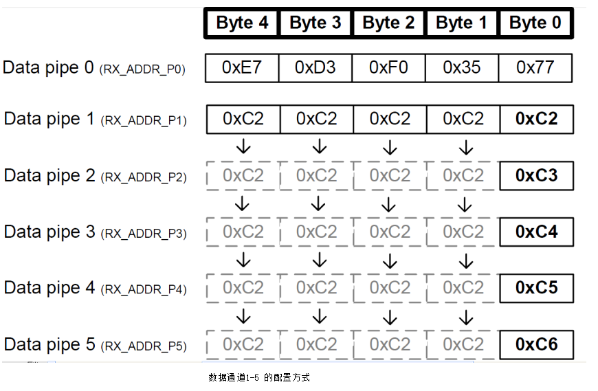
First of all, the address configuration should be noted that the channel P0 is arbitrary, but P1-P5 should pay attention to, give a map, regularly find their own.
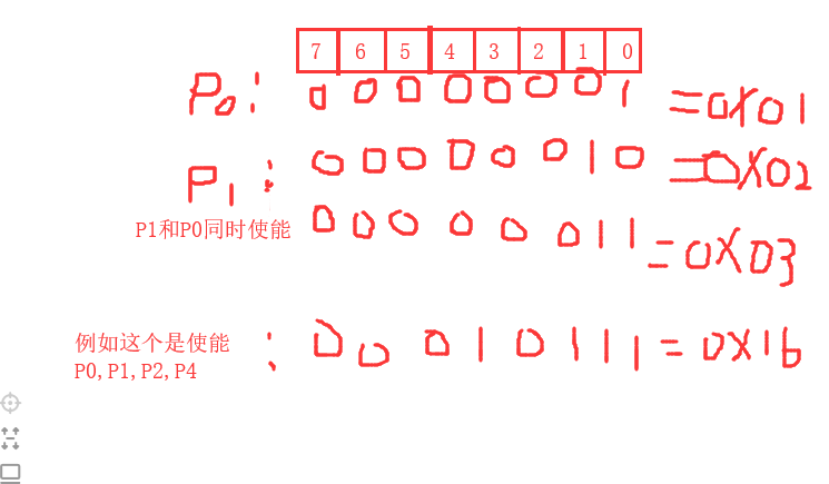
Multi-to-One Receiving Configuration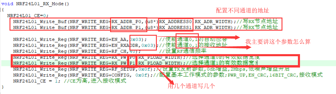 In my initial contact, I also did not understand why 0x01 is enabling channel 0, 0X02 is enabling channel 1 and 0X03 is enabling channel 1 and 0, not channel 2. The manual tells us that there are 8 bits of this parameter, and the last 6 bits of this parameter set up the channel. 1 is valid, 0 is invalid. Next I'll illustrate it.
Look at the receiving program again, because I have turned over many blogs, most of them only give many-to-one receiving configuration programs, but not how to receive and judge different channels of data.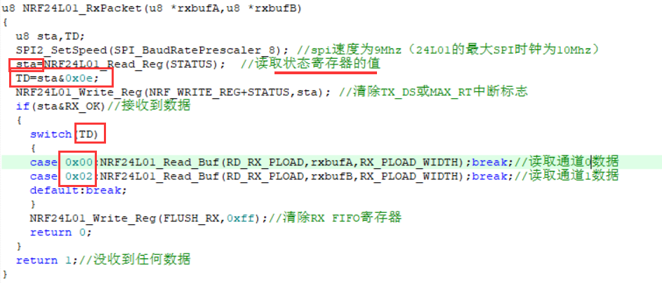
Many people see this and ask why 0X00 is Channel 0 and 0X02 is Channel 1. I'll continue to illustrate the status register. Officially, the number 0 defaults to 0, and the number 1 to 3 represents the channel number.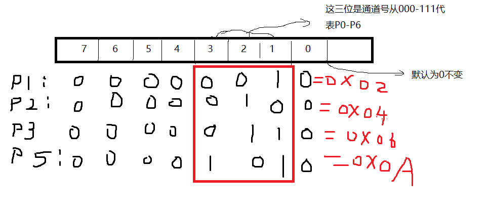
So the sum of sta value and 0X0e is to find the channel number, and then use switch statement to determine which channel value is received at the moment, and then pay the corresponding parameters.
As for the sender, the configuration is the same as the one-to-one sender configuration. As long as the sending address is the same as the receiving address of the corresponding channel.
summary
Because I read a lot of blogs before, I didn't mention how the value came from. Today I still read the technical manual to understand. Although most of the development of STM32 is Copy, we still need to understand the program. In case of mistakes, we also have some experience. I know it's probably wrong.
Problems encountered
I don't know if it's my configuration problem or nrf problem. After I've configured it, channel 0 from slave B is separated from host A.
Communication between slave C channel 1 and host A is normal, but slave C and slave B communicate with host at the same time, the host data receiving speed becomes slower, and occasionally errors occur. I don't know if I forgot what to configure or if I have a problem with the NRF. It's okay to test separately, but it's okay to test together. Please let me know if you encounter this kind of problem when communicating more to one (communication slows down or errors), or if there is a better solution in the comments section. Thank you.