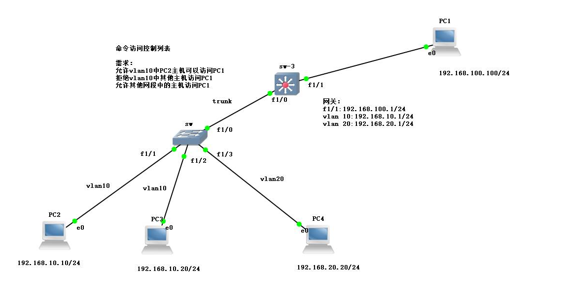
Practice environment deployment
Topology and requirements

Note: the capacity and business board of SW equipment and SW-3 equipment need to be added in advance
Practical steps
Step 1: configure SW switch
conf t                //Enter global mode, set VLAN 10 and 20
vlan 10,20
ex
do show vlan-sw b      //View vlan information

VLAN Name                             Status
10   VLAN0010                         active
20   VLAN0020                         active

int range fa1/1 -2          //Enter the fa1/1 and 1 / 2 interfaces, and transfer the port into vlan10.
sw mo acc
sw acc vlan 10
ex
do show vlan-sw b       //View vlan information

VLAN Name                             Status    Ports
10   VLAN0010                         active    Fa1/1, Fa1/2
20   VLAN0020                         active

int f1/3                //Enter port f1/3, and draw the port into VLAN 20
sw mo acc
sw acc vlan 20
ex
do show vlan-sw b

VLAN Name                             Status    Ports
10   VLAN0010                         active    Fa1/1, Fa1/2
20   VLAN0020                         active    Fa1/3

int f1/0          //Enter port f1/0 and configure trunk link
sw mo t
sw t en dot1q
ex
no ip routing          //Turn off routing
Step 2: configure SW-3 layer 3 switch
conf t
no switchport                //Switch off switching function
int f1/1
ip add 192.168.100.1 255.255.255.0
no shut
ex
vlan 10,20
ex
int vlan 10
ip add 192.168.10.1 255.255.255.0
no shut
ex
int vlan 20
ip add 192.168.20.1 255.255.255.0
no shut
ex
do show ip int b        //View vlan information

FastEthernet1/1            192.168.100.1   YES manual up                    up
Vlan10                     192.168.10.1    YES manual up                    down
Vlan20                     192.168.20.1    YES manual up                    down

int f1/0                   //Enter port f1/0 to configure trunk link
sw mo t
sw t en dot1q
do show ip route        //View routing table

C    192.168.10.0/24 is directly connected, Vlan10
C    192.168.20.0/24 is directly connected, Vlan20
C    192.168.100.0/24 is directly connected, FastEthernet1/1
Step 3: configure the client IP address and test the whole network interoperability
1. Configure the client IP address
PC1> ip 192.168.100.100 192.168.100.1
Checking for duplicate address...
PC1 : 192.168.100.100 255.255.255.0 gateway 192.168.100.1

PC2> ip 192.168.10.10 192.168.10.1
Checking for duplicate address...
PC1 : 192.168.10.10 255.255.255.0 gateway 192.168.10.1

PC3> ip 192.168.10.20 192.168.10.1
Checking for duplicate address...
PC1 : 192.168.10.20 255.255.255.0 gateway 192.168.10.1

PC4> ip 192.168.20.20 192.168.20.1
Checking for duplicate address...
PC1 : 192.168.20.20 255.255.255.0 gateway 192.168.20.1
2. Test the whole network interoperability
PC2> ping 192.168.100.100
192.168.100.100 icmp_seq=1 timeout
84 bytes from 192.168.100.100 icmp_seq=2 ttl=63 time=18.946 ms
84 bytes from 192.168.100.100 icmp_seq=3 ttl=63 time=19.942 ms
84 bytes from 192.168.100.100 icmp_seq=4 ttl=63 time=11.937 ms
84 bytes from 192.168.100.100 icmp_seq=5 ttl=63 time=17.674 ms

PC2> ping 192.168.10.20
84 bytes from 192.168.10.20 icmp_seq=1 ttl=64 time=0.000 ms
84 bytes from 192.168.10.20 icmp_seq=2 ttl=64 time=0.000 ms
84 bytes from 192.168.10.20 icmp_seq=3 ttl=64 time=0.000 ms
84 bytes from 192.168.10.20 icmp_seq=4 ttl=64 time=0.000 ms
84 bytes from 192.168.10.20 icmp_seq=5 ttl=64 time=0.000 ms

PC2> ping 192.168.20.20
192.168.20.20 icmp_seq=1 timeout
84 bytes from 192.168.20.20 icmp_seq=2 ttl=63 time=18.230 ms
84 bytes from 192.168.20.20 icmp_seq=3 ttl=63 time=21.964 ms
84 bytes from 192.168.20.20 icmp_seq=4 ttl=63 time=19.229 ms
84 bytes from 192.168.20.20 icmp_seq=5 ttl=63 time=11.992 ms
Step 4: configure naming ACL policy
Configure on SW-3 switch, in global mode
ip access-list standard yun          //Set the mode and name. Standard is the standard named ACL,extended is the extended named ACL.
permit host 192.168.10.10            //Set entries that allow access to host ip
deny 192.168.10.0 0.0.0.255        //Set rejected segment entries
permit any                                    //Set top to allow all other hosts to access
ex
do show access-list                   //View access list list

Standard IP access list yun
    10 permit 192.168.10.10
    20 deny   192.168.10.0, wildcard bits 0.0.0.255
    30 permit any

int f1/1                                       //Enter port f1/1, and apply ACL to this direction.
ip access-group yun out
Step 5: Test ACL effect
1. Test the interoperability between host 2 and host 1 in VLAN 10
PC2> ping 192.168.100.100
192.168.100.100 icmp_seq=1 timeout
192.168.100.100 icmp_seq=2 timeout
84 bytes from 192.168.100.100 icmp_seq=3 ttl=63 time=15.953 ms
84 bytes from 192.168.100.100 icmp_seq=4 ttl=63 time=19.232 ms
84 bytes from 192.168.100.100 icmp_seq=5 ttl=63 time=19.049 ms
2. Test the interoperability between host 4 and host 1
PC4> ping 192.168.100.100
84 bytes from 192.168.100.100 icmp_seq=1 ttl=63 time=20.226 ms
84 bytes from 192.168.100.100 icmp_seq=2 ttl=63 time=18.953 ms
84 bytes from 192.168.100.100 icmp_seq=3 ttl=63 time=18.208 ms
84 bytes from 192.168.100.100 icmp_seq=4 ttl=63 time=17.023 ms
84 bytes from 192.168.100.100 icmp_seq=5 ttl=63 time=12.985 ms
3. Testing the interoperability between other hosts in vlan10 and host 1
PC3> ping 192.168.100.100
*192.168.10.1 icmp_seq=1 ttl=255 time=8.907 ms (ICMP type:3, code:13, Communication administratively prohibited)
*192.168.10.1 icmp_seq=2 ttl=255 time=3.775 ms (ICMP type:3, code:13, Communication administratively prohibited)
*192.168.10.1 icmp_seq=3 ttl=255 time=7.979 ms (ICMP type:3, code:13, Communication administratively prohibited)
*192.168.10.1 icmp_seq=4 ttl=255 time=5.965 ms (ICMP type:3, code:13, Communication administratively prohibited)
*192.168.10.1 icmp_seq=5 ttl=255 time=1.992 ms (ICMP type:3, code:13, Communication administratively prohibited)
Note: the named access control list can flexibly adjust the policy, provided that on the basis of the standard access list and the extended access list, the no+ACL number deletion policy can be used, or the ACL number + permit+ip can be used to append the ACL policy.