In fact, we do machine vision on-line image acquisition and processing. The processing results determine the control signals that the computer will give, such as motor motion, so as to achieve real-time visual feedback motion. The acquisition in MIL needs the support of Matrox acquisition board. In this paper, the acquisition of MIL is explained with Matrox Helios board in laboratory as an example.
1. Composition of acquisition system
Speaking of acquisition, first of all, we must understand the composition of a complete acquisition system from hardware to software. The following schematic diagram of acquisition system uses Matrox board and MIL software. The detailed process of various CPU, MCU and GPU communication in the diagram is not expressed, but to illustrate the general process. In the actual process, the complete acquisition system is poor. Not too big. (In the future, I will consider a series of blog posts on machine vision hardware when I have time.
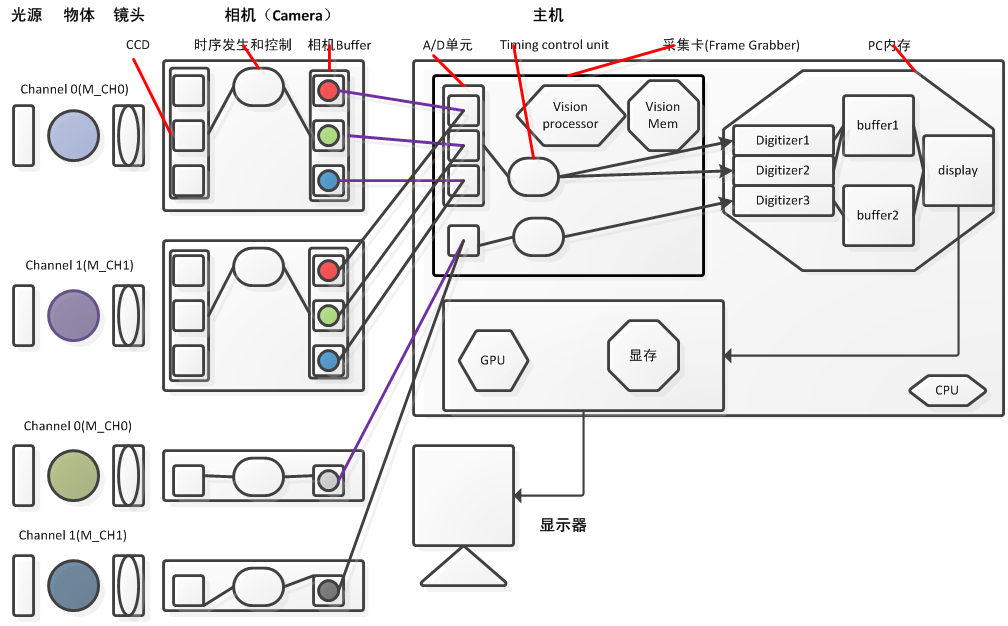
Comparing with the above figure, this paper briefly describes the process of drawing: under the illumination of light source, the reflected light of the object passes through the camera lens on the camera CCD (or CMOS) chip. This process is called Capture. The camera's timing controller controls the time interval to transfer the data from the CCD to the camera's buffer Buffer. This process is called Acquisition. Note that if the Buffer's data is not retrieved in time, the next acquisition will cover the previous data. The camera is connected to the Matrox board inserted into the PCI-E interface. The Time control unit on the board controls the retrieving of data from the Buffer in the camera. This process is called Grab, which is from the camera buffer. Analog or analog signal, in the card will do an A/D conversion through the A/D unit, the data will be converted to the corresponding quantized value stored in the corresponding MIL buffer, this process is called Digtize. Here, the output of Capture and Acquisition in Camera is analog signal. This camera is analog camera. Grab and Digtize are accomplished in Frame Grabber. Generally, Camera Link interface is used between the camera and the card, and 1394 interface is also used for high-speed acquisition. In fact, this is also the practice of most ordinary industrial cameras (13fps-30fps). They output digital signals, called digital cameras, and generally use GigE, 1394 or USB interfaces. Note that here I use four English words named Capture, Acquisition, Grab and Digtize, which can be translated into acquisition. Some words in English have similar meanings but have subtle differences. There is no way to distinguish their meanings clearly in Chinese. In fact, what we usually call acquisition is standing on PC. From the perspective of volume image, it is the general name of these four processes.
When we operate the whole acquisition process in the PC, MIL provides us with the distributed Digitizer object for acquisition, corresponding to the Mdig start function. It is very important to specify a DCF(Device Configure File) file when distributing Digitizer objects. This file defines the frequency and resolution of Grab, etc. Simply speaking, it is the frequency at which the camera timing controller stores data to the camera Buffer and the board timing control unit obtains data from the camera Buffer. Frequency must have a matching relationship. The default MIL installation allows users to set up a default DCF file, which is used by default when distributing Digtizer. MIL provides a series of DCF files corresponding to the camera. If not, you can also customize DCF files in MIL Intellicam. The same camera can use different DCF files when defining Digtizer. The frequency of the set and the size of the collected image, such as Digtizer 1 and Digtizer 2, can be adjusted in real time after defining Digtizer. The corresponding acquisition parameters in DCF can be adjusted by MdigControl function.
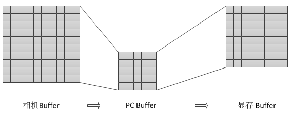
The following illustrations illustrate several concepts, which are helpful for you to read the manual:
Acquisition path: From Capture to Acquisition, Grab to Digtize, there are six Acquisition paths for color cameras (RGB each counts one channel, that is, you can use color cameras as monochrome cameras). For monochrome cameras, there are two Acquisition paths, each Acquisition pat. H must contain a Time control unit. Several Digtizers can be connected to each Acquisition path, such as Digtizer 1 and Digitizer2, but only one Digtizer can work on the same Acquisition path at a time. You can pre-assign multiple Digtizers and switch when needed.
Independent acquisition path: A Time control unit can only control one Acquisition path acquisition at a time. If two cameras want to achieve simultaneous acquisition, they must use two Time Control Units. Two Acquisition paths with different Time Control Units are called Independent acquisition path. As shown in the figure, the Acquisition path between the color camera and the monochrome camera is the Independent acquisition path, which can be collected at the same time. Digtizer connected to two Independent acquisition paths can work simultaneously to extract maps.
Data input channel (channel): We often hear that dual-channel acquisition is that the same Time control unit's Capture source is divided into multiple, each called a channel, in the acquisition time can switch acquisition, but not simultaneously acquisition.
Device Number: When allocating Digtizer in MIL, it is required to specify the device number of the first Acquisition path of each channel. MIL automatically calculates the total number of Acquisition paths based on the corresponding DCF file. For example, if R Acquisition path of color camera of channel 0 is M_DEV0, then G Acquisition path and B Acquisition path phases It should be M_DEV1 and M_DEV2. Channel 0 monochrome cameras can only be assigned Device Numbers starting with M_DEV3. If the board has only one Time control unit, it must be specified as M_DEV0 or M_DEFAULT.
2.MIL acquisition and real-time display
MdigGrab
	//Allocate default applications and systems
	MappAllocDefault(M_SETUP, &MilApplication, &MilSystem, M_NULL, M_NULL, M_NULL);

	//Distribution collector
	MdigAlloc(MilSystem, M_DEFAULT, "M_DEFAULT", M_DEFAULT, &MilDigitizer);

	int nGrabScaleSet = 4;//Setting the acquisition ratio

	//Allocate buffer
	if (MsysInquire(MilSystem, M_SYSTEM_TYPE, M_NULL) == M_SYSTEM_HELIOS_TYPE)
	{
		   BufferLocation = M_ON_BOARD;
	}
	MbufAlloc2d(MilSystem,
				long(MdigInquire(MilDigitizer, M_SIZE_X, M_NULL) / nGrabScaleSet),
				long(MdigInquire(MilDigitizer, M_SIZE_Y, M_NULL) / nGrabScaleSet),
				MdigInquire(MilDigitizer, M_TYPE, M_NULL),
				M_DISP + M_IMAGE + M_GRAB + BufferLocation,
				&MilBufferImage);
	MbufClear(MilBufferImage, 0xFF);

	//Allocation display
	MdispAlloc(MilSystem, M_DEFAULT, "M_DEFAULT",  M_WINDOWED, &MilDisplay);

	//Buffer and Display bindings
	MdispSelectWindow(MilDisplay, MilBufferImage, GetDlgItem(IDS_DISPLAY)->GetSafeHwnd());

	//Single-frame acquisition of two frames
	MdigControl(MilDigitizer, M_GRAB_SCALE_X, 1.0/nGrabScaleSet);
	MdigControl(MilDigitizer, M_GRAB_SCALE_Y, 1.0/nGrabScaleSet);
	MdigControl(MilDigitizer, M_GRAB_MODE, M_ASYNCHRONOUS );
	MdigGrab(MilDigitizer, MilBufferImage);
	Sleep(1000);//Pause for a second
	MdispZoom(MilDisplay, 2, 2);
	MdigGrab(MilDigitizer, MilBufferImage);
	Sleep(1000);//Pause for a second

	//Releasing resources
	if (M_NULL != MilBufferImage)
	{
		MbufFree(MilBufferImage);
	}
	if (M_NULL != MilDisplay)
	{
		MdispFree(MilDisplay);
	}
	if (M_NULL != MilDigitizer)
	{
		MdigFree(MilDigitizer);
	}
	if (M_NULL != MilApplication)
	{
		MappFreeDefault(MilApplication, MilSystem, M_NULL, M_NULL, M_NULL);
}It should also be noted that there are two basic modes of acquisition, asynchronism and synchronization, and generally acquisition asynchronism (M_ASYNCHRONOUS). For the specific meaning, please consult the MIL manual.
MdigGrabContinuous
	//Allocate default applications and systems
	MappAllocDefault(M_SETUP, &MilApplication, &MilSystem, M_NULL, M_NULL, M_NULL);

	//Distribution collector
	MdigAlloc(MilSystem, M_DEFAULT, "M_DEFAULT", M_DEFAULT, &MilDigitizer);

	int nGrabScaleSet = 4;//Setting the acquisition ratio

	//Allocate buffer
	if (MsysInquire(MilSystem, M_SYSTEM_TYPE, M_NULL) == M_SYSTEM_HELIOS_TYPE)
	{
		   BufferLocation = M_ON_BOARD;
	}
	MbufAlloc2d(MilSystem,
				long(MdigInquire(MilDigitizer, M_SIZE_X, M_NULL) / nGrabScaleSet),
				long(MdigInquire(MilDigitizer, M_SIZE_Y, M_NULL) / nGrabScaleSet),
				MdigInquire(MilDigitizer, M_TYPE, M_NULL),
				M_DISP + M_IMAGE + M_GRAB + BufferLocation,
				&MilBufferImage);
	MbufClear(MilBufferImage, 0xFF);

	//Allocation display
	MdispAlloc(MilSystem, M_DEFAULT, "M_DEFAULT",  M_WINDOWED, &MilDisplay);

	//Buffer and Display bindings
	MdispSelectWindow(MilDisplay, MilBufferImage, GetDlgItem(IDS_DISPLAY)->GetSafeHwnd());

	//Start continuous acquisition
MdigGrabContinuous(MilDigitizer, MilBufferImage); MdigHalt(MilDigitizer);
//Releasing resources
if (M_NULL != MilBufferImage)
{
MbufFree(MilBufferImage);
}
if (M_NULL != MilDisplay)
{
MdispFree(MilDisplay);
}
if (M_NULL != MilDigitizer)
{
MdigFree(MilDigitizer);
}
if (M_NULL != MilApplication)
{
MappFreeDefault(MilApplication, MilSystem, M_NULL, M_NULL, M_NULL);
}MdigProcess
	// TODO: Add your control notification handler code here
	//Allocate default applications and systems
	MappAllocDefault(M_SETUP, &MilApplication, &MilSystem, M_NULL, M_NULL, M_NULL);

	//Distribution collector
	MdigAlloc(MilSystem, M_DEFAULT, "M_DEFAULT", M_DEFAULT, &MilDigitizer);

	//Allocate display buffer
	MbufAlloc2d(MilSystem,
				long(MdigInquire(MilDigitizer, M_SIZE_X, M_NULL)),
				long(MdigInquire(MilDigitizer, M_SIZE_Y, M_NULL)),
				MdigInquire(MilDigitizer, M_TYPE, M_NULL),
				M_DISP + M_IMAGE,
				&MilBufferImage);
	MbufClear(MilBufferImage, 0xFF);

	//Allocation display
	MdispAlloc(MilSystem, M_DEFAULT, "M_DEFAULT",  M_WINDOWED, &MilDisplay);

	//Buffer and Display bindings
	MdispSelectWindow(MilDisplay, MilBufferImage, GetDlgItem(IDS_DISPLAY)->GetSafeHwnd());


	/************************************************************************/
	/* Assign Buffer List */
	/************************************************************************/
    MappControl(M_ERROR, M_PRINT_DISABLE);

	//Initialize buffer list
	for(m = 0; m < BUFFERING_SIZE_MAX; m++)
	{
		MilGrabBufferList[m] = M_NULL;
	}

	//Allocate as many buffer list s as possible
	if (MsysInquire(MilSystem, M_SYSTEM_TYPE, M_NULL) == M_SYSTEM_HELIOS_TYPE)
	{
		BufferLocation = M_ON_BOARD;
	}
	MilGrabBufferListSize=0;
	for(m = 0; m < BUFFERING_SIZE_MAX; m++)
	{
		//Assign a Buffer
		MbufAlloc2d(MilSystem,
					MdigInquire(MilDigitizer, M_SIZE_X, M_NULL),
					MdigInquire(MilDigitizer, M_SIZE_Y, M_NULL),
					MdigInquire(MilDigitizer, M_TYPE, M_NULL),
					M_IMAGE+M_GRAB+M_PROC+BufferLocation,
					&MilGrabBufferList[m]);

		if (MilGrabBufferList[m])//Initialization if allocation is successful
		{
			MbufClear(MilGrabBufferList[m], 0xFF);

			LastAllocatedM = m;
			MilGrabBufferListSize++;
		}
		else//If the allocation fails, the allocation stops.
		{
			break;
		}
	}

	MappControl(M_ERROR, M_PRINT_ENABLE);

	//Prevent running out of memory and release the last buffer
	MbufFree(MilGrabBufferList[LastAllocatedM]);
	MilGrabBufferList[LastAllocatedM] = M_NULL;
	MilGrabBufferListSize--;//Note that the size-1 must be released here, otherwise MdigProcess detection will be called.
							//When the actual available buffer size does not match the imported size parameter, an error will be reported.

	/************************************************************************/
	/*Acquisition and processing*/
	/************************************************************************/
	//Setting up the data to be passed
	UserHookData.MilImageDisp        = MilBufferImage;
	UserHookData.ProcessedImageCount = 0;

	MdigProcess(MilDigitizer, MilGrabBufferList, MilGrabBufferListSize,
M_START, M_DEFAULT, ProcessingFunction, &UserHookData); /************************************************************************/
/*Stop acquisition and processing*/
/************************************************************************/
MdigProcess(MilDigitizer, MilGrabBufferList, MilGrabBufferListSize,
M_STOP, M_DEFAULT, ProcessingFunction, &UserHookData);
//Releasing resources
MappControl(M_ERROR, M_PRINT_DISABLE);
for (m = 0; m < BUFFERING_SIZE_MAX; m++)
{
if(M_NULL != MilGrabBufferList[m])
{
MbufFree(MilGrabBufferList[m]);
MilGrabBufferList[m] = M_NULL;
}
}
if (M_NULL != MilBufferImage)
{
MbufFree(MilBufferImage);
}
if (M_NULL != MilDisplay)
{
MdispFree(MilDisplay);
}
if (M_NULL != MilDigitizer)
{
MdigFree(MilDigitizer);
}
MappControl(M_ERROR, M_PRINT_ENABLE);
if (M_NULL != MilApplication)
{
MappFreeDefault(MilApplication, MilSystem, M_NULL, M_NULL, M_NULL);
}long MFTYPE ProcessingFunction(long HookType, MIL_ID HookId, void MPTYPE *HookDataPtr)
{
HookDataStruct *UserHookDataPtr = (HookDataStruct *)HookDataPtr;
MIL_ID ModifiedBufferId;
char Text[10]= {'\0'};
//Get the buffer list to get the buffer number of the collected data
MdigGetHookInfo(HookId, M_MODIFIED_BUFFER+M_BUFFER_ID, &ModifiedBufferId);
UserHookDataPtr->ProcessedImageCount++;
//Write the acquisition number on the current picture
MOs_ltoa(UserHookDataPtr->ProcessedImageCount, Text, 10);
MgraText(M_DEFAULT, ModifiedBufferId, 10, 10, Text);
//Copy the processed Buffer data to the display buffer
MbufCopy(ModifiedBufferId, UserHookDataPtr->MilImageDisp);
return 0;
}Originality, reprint please indicate from http://blog.csdn.net/wenzhou1219
Reprinted at: https://www.cnblogs.com/riasky/p/3455541.html