PWM mode
The pulse width modulation mode can be generated by TIM1_ The ARR register determines the frequency, which is determined by TIM1_ The ccrx register determines the signal of the duty cycle.
At TIM1_ The OCxM bit in ccmrx register is written to '110' (PWM mode 1) or '111' (PWM mode 2), and each OCx output channel can be independently set to generate one PWM. TIM1 must be set_ The OCxPE bit of ccmrx register enables the corresponding preload register, and finally sets TIM1_ The ARPE bit of the CR1 register (in count up or centrosymmetric mode) enables the preloaded register to be reloaded automatically.
The preload register can be transferred to the shadow register only when an update event occurs. Therefore, before the counter starts counting, you must set TIM1_ UG bit in EGR register to initialize all registers.
The polarity of OCx can be displayed in TIM1 through software_ The CCxP bit in the CCER register is set, which can be set to high level valid or low level valid. The output enable of OCx is controlled by the combination of CCxE, CCxNE, MOE, OSSI and OSSR bits (in TIM1_CCER and TIM1_BDTR registers). See TIM1 for details_ Description of CCER register.
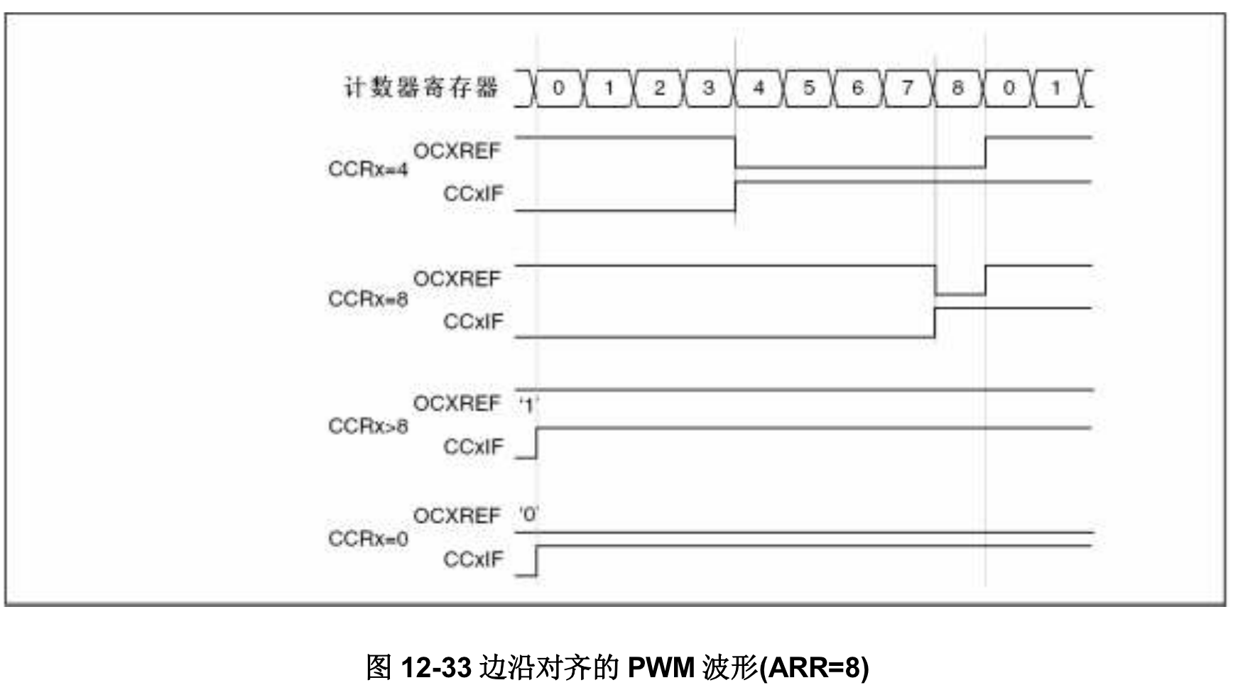
In PWM mode (mode 1 or mode 2), TIM1_CNT and TIM1_CCRx is always compared (according to the counting direction of the counter) to determine whether TIM1 is met_ CCRx≤TIM1_CNT or TIM1_CNT≤TIM1_CCRx. According to TIM1_ According to the status of CMS bit in CR1 register, the timer can generate edge aligned PWM signal or center aligned PWM signal.
PWM center alignment mode
When TIM1_ When the CMS bit in CR1 register is not '00', it is in the central alignment mode (all other configurations have the same effect on OCxREF/OCx signals). According to different CMS bit settings, the comparison flag can be set to 1 when the counter counts up, 1 when the counter counts down, or 1 when the counter counts up and down. TIM1_ The count direction bit (DIR) in CR1 register is updated by hardware. Do not modify it with software.
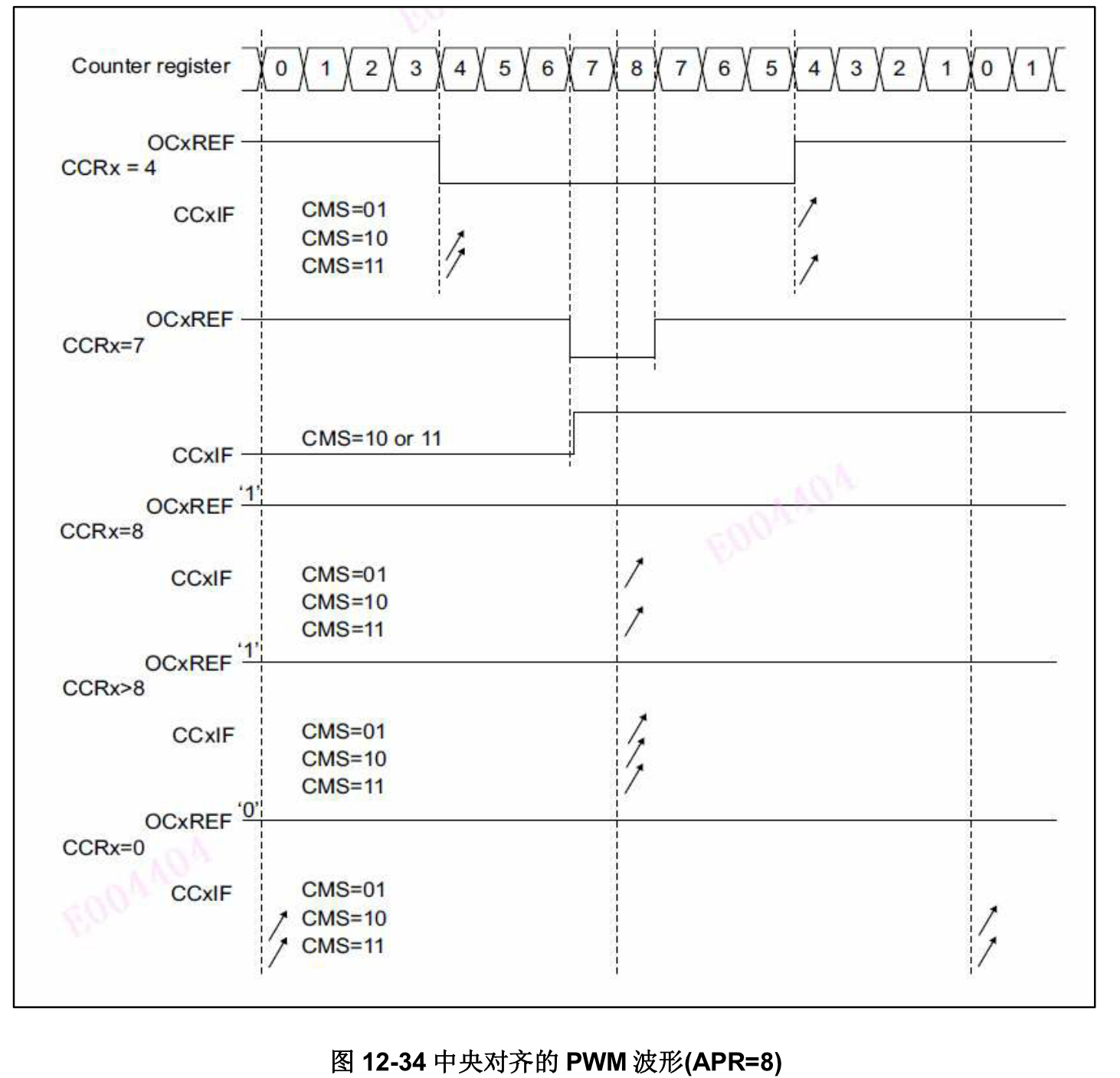
The following figure shows some examples of centrally aligned PWM waveforms
⚫ TIM1_ARR=8
⚫ PWM mode 1
⚫ TIM1_ CMS of CR1 register = 01. In central alignment mode 1, the comparison flag is set when the counter counts down.
Tips for using center alignment mode:
⚫ When entering the center alignment mode, the current up / down count configuration is used. This means that whether the counter counts up or down depends on TIM1_ The current value of the DIR bit in the CR1 register. In addition, the software cannot modify the DIR and CMS bits at the same time.
⚫ Rewriting the counter when running in central alignment mode is not recommended because it can produce unpredictable results. In particular:
- If the value of the write counter is greater than the value of the automatic reload (tim1_cnt > tim1_arr), the direction is not updated.
For example, if the counter is counting up, it will continue to count up. - If 0 or 1_ The value of arr is written to the counter, and the direction is updated, but no update event UEV is generated.
⚫ The safest way to use the central alignment mode is to generate a software update (set the UG bit in the TIM1_EGR bit) before starting the counter, and do not modify the counter value during counting.
/********************************************************************************
* @file    bsp_pwm.c
* @author  jianqiang.xue
* @version V1.0.0
* @date    2021-04-18
* @brief   NULL
********************************************************************************/

/* Includes ------------------------------------------------------------------*/
#include "RTE_Components.h"
#include CMSIS_device_header

#include "bsp_gpio.h"
#include "bsp_tim.h"
#include "bsp_pwm.h"

/* Private Includes ----------------------------------------------------------*/
#include "business_gpio.h"
#include "business_function.h"

/* Private Variables ---------------------------------------------------------*/
static bool g_pwm_init = false;

#if BS_TIM1_EN
extern TIM_HandleTypeDef tim1_handle_t;
extern TIM_OC_InitTypeDef tim1_oc_init_handle_t;
#endif

/* Public function prototypes -----------------------------------------------*/
/**
 * @brief  PWN Function initialization, use timer and ppi to simulate PWM function
 * @note   NULL
 * @retval None
 */
void bsp_pwm_init(void)
{
    if (g_pwm_init)
    {
        return;
    }
#if BS_TIM1_EN
    bsp_tim_pwm_init();
	g_pwm_init = true;
#endif
}

/**
 * @brief  PWN Function off
 * @note   NULL
 * @retval None
 */
void bsp_pwm_deinit(void)
{
    if (!g_pwm_init)
    {
        return;
    }
#if BS_TIM1_EN
	bsp_tim_pwm_deinit();
    g_pwm_init = false;
#endif
}

/**
 * @brief  Set PWM duty cycle
 * @note   NULL
 * @param  pwmx: PWM Group number
 * @param  val: 0-100 PWM value
 * @retval None
 */
void bsp_pwm_set_pulse(bsp_pwm_t pwmx, uint16_t val)
{
    if (!g_pwm_init)
    {
        return;
    }
    if (pwmx == BSP_PWM_0)
    {
#if BS_TIM1_EN && BS_PWM0_EN
        HAL_TIM_PWM_Stop(&tim1_handle_t, TIM_CHANNEL_1);
        tim1_oc_init_handle_t.Pulse = val;
        HAL_TIM_PWM_ConfigChannel(&tim1_handle_t, &tim1_oc_init_handle_t, TIM_CHANNEL_1);
        HAL_TIM_PWM_Start(&tim1_handle_t, TIM_CHANNEL_1);
#endif
    }
    else if (pwmx == BSP_PWM_1)
    {
#if BS_TIM1_EN && BS_PWM1_EN
        HAL_TIM_PWM_Stop(&tim1_handle_t, TIM_CHANNEL_2);
        tim1_oc_init_handle_t.Pulse = val;
        HAL_TIM_PWM_ConfigChannel(&tim1_handle_t, &tim1_oc_init_handle_t, TIM_CHANNEL_2);
        HAL_TIM_PWM_Start(&tim1_handle_t, TIM_CHANNEL_2);
#endif
    }
    else if (pwmx == BSP_PWM_2)
    {
#if BS_TIM1_EN && BS_PWM2_EN
        HAL_TIM_PWM_Stop(&tim1_handle_t, TIM_CHANNEL_3);
        tim1_oc_init_handle_t.Pulse = val;
        HAL_TIM_PWM_ConfigChannel(&tim1_handle_t, &tim1_oc_init_handle_t, TIM_CHANNEL_3);
        HAL_TIM_PWM_Start(&tim1_handle_t, TIM_CHANNEL_3);
#endif
    }
    else if (pwmx == BSP_PWM_3)
    {
#if BS_TIM1_EN && BS_PWM3_EN
        HAL_TIM_PWM_Stop(&tim1_handle_t, TIM_CHANNEL_4);
        tim1_oc_init_handle_t.Pulse = val;
        HAL_TIM_PWM_ConfigChannel(&tim1_handle_t, &tim1_oc_init_handle_t, TIM_CHANNEL_4);
        HAL_TIM_PWM_Start(&tim1_handle_t, TIM_CHANNEL_4);
#endif
    }
}
/********************************************************************************
* @file    bsp_pwm.h
* @author  jianqiang.xue
* @version V1.0.0
* @date    2021-04-18
* @brief   NULL
********************************************************************************/

#ifndef __BSP_PWM_H
#define __BSP_PWM_H

/* Includes ------------------------------------------------------------------*/
#include <stdint.h>

/* Public enum ---------------------------------------------------------------*/
typedef enum
{
    BSP_PWM_0 = 0,
    BSP_PWM_1,
    BSP_PWM_2,
    BSP_PWM_3,
    BSP_PWM_4,
    BSP_PWM_5,
    BSP_PWM_6,
    BSP_PWM_7,
    BSP_PWM_8,
    BSP_PWM_9,
    BSP_PWM_10,
    BSP_PWM_11
} bsp_pwm_t;

/* Public Function Prototypes ------------------------------------------------*/

void bsp_pwm_init(void);
void bsp_pwm_deinit(void);

void bsp_pwm_set_pulse(bsp_pwm_t pwmx, uint16_t val);

#endif