1 Introduction to LVS
1.1 introduction to LVS
The architecture and principle of LB cluster is very simple, that is, when the user's request comes, it will be directly distributed to the Director Server, and then it will intelligently and evenly distribute the user's request to the back-end real server according to the set scheduling algorithm. In order to avoid different data requested by users on different machines, shared storage is needed to ensure that the data requested by all users are the same
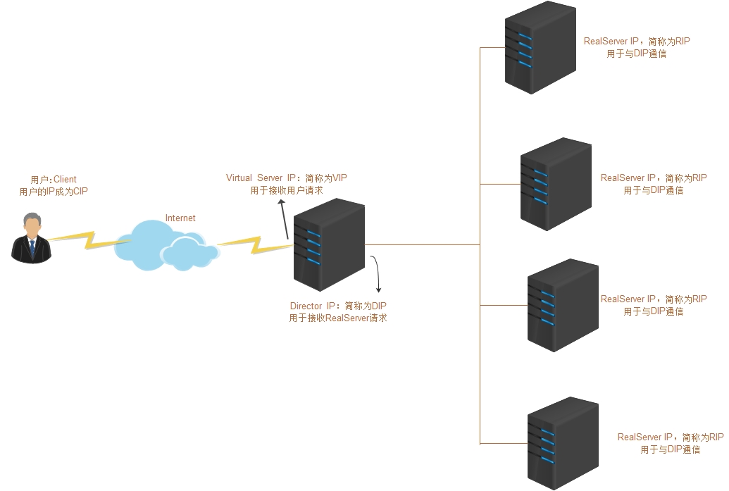
LVS (Linux Virtual Server), namely Linux virtual server, is an open source load balancing project led by DR. Zhang wensong. At present, LVS has been integrated into the Linux kernel module. The project implements an IP based data request load balancing scheduling scheme in the Linux kernel. Its architecture is shown in Figure 1. The end Internet user accesses the company's external load balancing server from the outside, and the end user's Web request will be sent to the LVS scheduler. The scheduler decides to send the request to a back-end Web server according to its preset algorithm, for example, The polling algorithm can evenly distribute external requests to all servers at the back end. Although the end user accessing the LVS scheduler will be forwarded to the real server at the back end, if the real server is connected to the same storage and provides the same service, the end user will get the same service content no matter which real server he accesses, The whole cluster is transparent to users. Finally, according to different LVS working modes, the real server will choose different ways to send the data required by the user to the end user. LVS working modes are divided into NAT mode, TUN mode, DR mode and FULL NAT mode
1.2 why if there is LVS
Through the load balancing technology achieved by LVS and Linux operating system, a high-performance and high availability Linux Server cluster is realized, which has good reliability, scalability and operability. So as to achieve optimal performance at low cost. LVS is an open source software project to realize load balancing cluster. LVS architecture can be logically divided into scheduling layer, Server cluster layer and shared storage layer
To solve the high pressure of multi server workload, that is to build a scalable network service system on the server cluster. When the load increases, you can simply add new servers or more servers in the cluster to meet the growing demand, while commercial servers have the highest performance / cost ratio. Therefore, building a server cluster system for network services is more scalable and cost-effective
1.3 roles in LVS
- Director (DR for short): scheduler (also known as Dispatcher, Balancer), which is mainly used to accept user requests
- Director Server (DS for short): refers to the front-end load balancer node
- Real Server (RS for short): real host, which is used to process user requests
- Director Virtual (VIP for short): the IP address used by the scheduler to communicate with the client, which is the target IP address requested by the user
- Director IP is referred to as DIP: the IP address used by the scheduler to communicate with RealServer, which is mainly used to communicate with internal hosts
- Real Server IP referred to as RIP: the IP address of the back-end server
- Client IP referred to as CIP: the IP address of the client
1.4 basic model of LVS
2 working principle of LVS
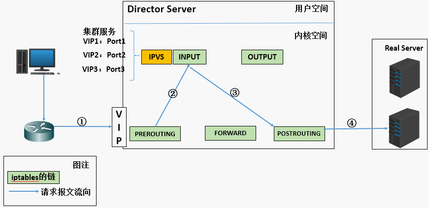
- When the user sends a request to the load balancing scheduler (Director Server), the scheduler sends the request to the kernel space
- The provisioning chain will first receive the user request, judge the target IP, determine the local IP, and send the data packet to the INPUT chain
- IPVS works on the INPUT chain. When the user request reaches the INPUT, IPVS will compare the user request with the defined cluster service. If the user requests the defined cluster service, IPVS will forcibly modify the target IP address and port in the packet and send the new packet to the POSTROUTING chain
- After the POSTROUTING link receives the data packet, it is found that the target IP address is just its own back-end server. At this time, the data packet is finally sent to the back-end server through routing
3 LVS scheduling algorithm
lvs scheduler: lvs scheduler, that is, the algorithm for lvs to select RS
3.1 static algorithm scheduling
Scheduling is only based on the algorithm itself
-
RR: round robin, polling
This algorithm is the simplest, which is to schedule requests to different servers in a cyclic manner. The biggest feature of this algorithm is simplicity. The polling algorithm assumes that all servers have the same ability to process requests. The scheduler will evenly distribute all requests to each real server, regardless of the back-end RS configuration and processing capacity -
WRR: weighted rr, weighted polling scheduling
This algorithm has A concept of weight more than rr's algorithm. It can set the weight for RS. the higher the weight, the more requests will be distributed, and the value range of the weight is 0 – 100. It is mainly an optimization and supplement to rr algorithm. LVS will consider the performance of each server and add A weight to each server. If the weight of server A is 1 and the weight of server B is 2, the request dispatched to server B will be twice that of server A. The higher the weight, the more requests are processed -
SH: source hash, the source address hash scheduling algorithm, implements the session holding mechanism
It is similar to the target address hash scheduling algorithm, but it statically allocates fixed server resources according to the source address hash algorithm -
DH: destination hash, target address hash scheduling algorithm
The algorithm establishes a mapping relationship between the target IP and the server through the hash function according to the target IP address. When the server is unavailable or the load is too high, the request sent to the target IP will be sent to the server
3.2 dynamic algorithm scheduling
Schedule according to the algorithm and the current load state of each RS, calculate the overhead according to the specified algorithm, and finally select the RS with the lowest overhead value
-
LC: Least Connection. The algorithm is as follows:
overhead = Active * 256 + Inactive
This algorithm will decide who to distribute the request according to the number of connections of the back-end rs. for example, if the number of RS1 connections is less than that of RS2 connections, the request will be sent to RS1 first -
WLC: Weighted LC, Weighted LC (minimum number of connections). The algorithm is as follows:
overhead=(Active*256+Inactive)/ weight
The algorithm has a more weight concept than lc -
LBLC: locality based LC, a locality based least connection scheduling algorithm
This algorithm is a scheduling algorithm for the target IP address of the request packet. The algorithm first finds all the servers used by the nearest target IP address according to the requested target IP address. If this server is still available and capable of processing the request, the scheduler will select the same server as much as possible, otherwise it will continue to select other feasible servers -
LBLCR: locality based least connection with replication, a complex connection algorithm based on least locality
Instead of recording the connection between the target IP and a server, it will maintain the mapping relationship between a target IP and a group of servers to prevent the single point server from being overloaded -
SED: shortest expectation delay. The algorithm is as follows:
overhead = (Active + 1) * 256 / weight -
NQ: Nevel Queue is an improvement of SED algorithm. According to sed algorithm, each host must be allocated at least once for the first time, and then selected according to sed algorithm to never queue
4 ipvs and ipvsadm
4.1 ipvs
ipvs(ip virtual server): a piece of code that works in the kernel space, called ipvs, is the code that really takes effect to realize scheduling
4.1.1 cluster service of IPVS
Support TCP, UDP, AH, EST, AH_EST, SCTP and many other protocols
4.1.2 characteristics of IPVS cluster service
- An ipvs host can define multiple cluster service s at the same time
- lvs type (the mode of lvs) and lvs scheduler (scheduler) are specified when defining
- There should be at least two real server s on a cluster service
4.2 ipvsadm
- Ipvsadm: another section works in the user space, called ipvsadm, which is responsible for writing rules for the ipvs kernel framework to define who is the cluster service and who is the real server at the back end
4.2.1 usage of ipvsadm
- Manage cluster services
ipvsadm -A|E -t|u|f service-address [-s scheduler] [-p [timeout]] [-M netmask]
ipvsadm -D -t|u|f service-address

common service-address
tcp: -t ip:port
            udp: -u ip:port
            fwm: -f mark
        -s scheduler:
            Default to wlc
        -p [timeout]: Define persistent connections, timeout If not specified, the default is 300 seconds
- Managing RS in cluster services
 ipvsadm -a|e -t|u|f service-address -r server-address [-g|i|m] [-w weight] [-x upper] [-y lower]
        ipvsadm -d -t|u|f service-address -r server-address
        ipvsadm -L|l [options]

        server-address:
            ip[:port]
        lvs-type:
            -g: gateway,dr pattern
            -i: ipip,tun pattern
            -m: masquerade,nat pattern
    -w: Set the weight, which can be from 0 to positive infinity. When it is set to 0, it will not be scheduled, and the default is 1
        The larger the weight value, the better the performance and more resources will be scheduled
- Empty and view
 ipvsadm -C	empty
        ipvsadm -L|l [options]	see
            options:
            -n: numeric,Displays addresses and ports based on numeric format
            -c: connection,Show current ipvs connect
            --stats: statistical data
            --rate: Output rate information
            --exact: Display the exact value without unit conversion
- Save and reload
  ipvsadm -R	heavy load
        ipvsadm -S [-n] 	preservation
- Zero setting counter
ipvsadm -Z [-t|u|f service-address]
5 three dispatching modes of LVS
5.1 principle and characteristics of LVS / nat
Understand the implementation principle of NAT mode and the change of data packet
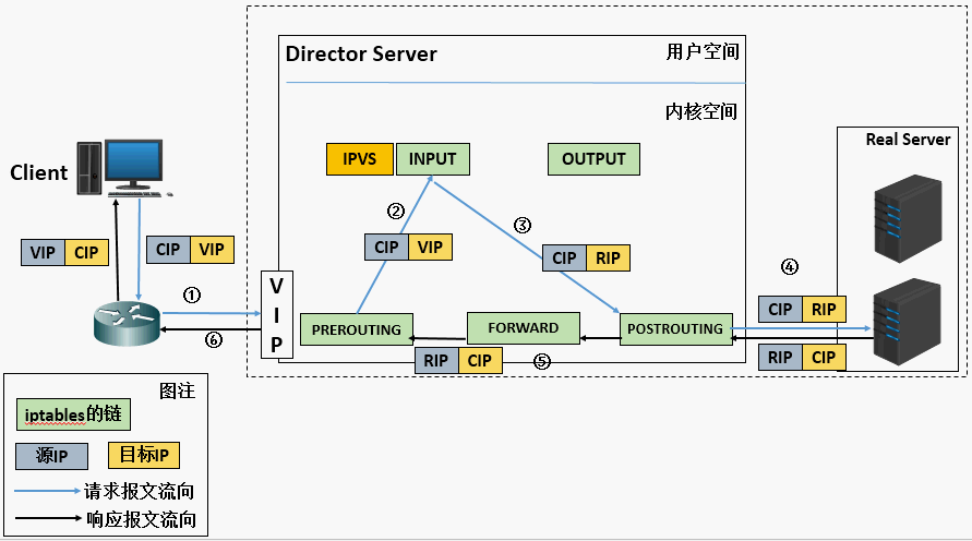
- When the user request arrives at the Director Server, the requested data message will first arrive at the preouting chain in the kernel space. At this time, the source IP of the message is CIP and the target IP is VIP
- The preouting check finds that the destination IP of the packet is local, and sends the packet to the INPUT chain
- IPVS compares whether the service requested by the packet is a cluster service. If so, modify the target IP address of the packet to the back-end server IP, and then send the packet to the POSTROUTING chain. At this time, the source IP of the message is CIP and the target IP is RIP
- The POSTROUTING chain sends packets to the Real Server through routing
- The Real Server compares and finds that the target is its own IP, starts to build a response message and sends it back to the Director Server. At this time, the source IP of the message is RIP and the target IP is CIP
- Before responding to the client, the Director Server will modify the source IP address to its own VIP address, and then respond to the client. At this time, the source IP of the message is VIP and the target IP is CIP
5.1.1 characteristics of lvs-nat model
- RS should use private address, and RS gateway must point to DIP
- DIP and RIP must be in the same network segment
- Both request and response messages need to pass through the Director Server. In high load scenarios, the Director Server is easy to become a performance bottleneck
- Support port mapping
- RS can use any operating system
- There will be great pressure on the director server. Requests and responses need to go through the director server
- The advantage of using nat is that the back-end hosts are relatively secure
5.2 principle and characteristics of LVS / DR
Reset the target MAC address of the request message to the MAC address of the selected RS
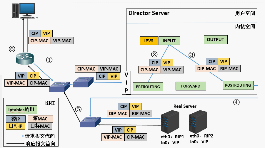
- When the user request arrives at the Director Server, the requested data message will first arrive at the preouting chain in the kernel space. At this time, the source IP of the message is CIP and the target IP is VIP
- The preouting check finds that the destination IP of the packet is local, and sends the packet to the INPUT chain
- IPVS compares whether the service requested by the packet is a cluster service. If so, modify the source MAC address in the request message to the MAC address of DIP, modify the target MAC address to the MAC address of RIP, and then send the packet to the POSTROUTING chain. At this time, the source IP and destination IP are not modified. Only the MAC address whose source MAC address is DIP and the destination MAC address is RIP are modified
- Since DS and RS are in the same network, they are transmitted through layer 2. The POSTROUTING chain checks that the target MAC address is the MAC address of RIP, and then the packet will be sent to the Real Server.
- When RS finds that the MAC address of the request message is its own MAC address, it receives the message. After processing, the response message is transmitted to eth0 network card through lo interface, and then sent out. At this time, the source IP address is VIP and the target IP is CIP
- The response message is finally delivered to the client
5.2.1 characteristics of lvs-dr model
- Ensure that the front-end route sends all messages with the target address of VIP to the Director Server instead of RS
- RS can use private address; It can also be a public network address. If you use a public network address, you can directly access RIP through the Internet
- RS and Director Server must be in the same physical network
- All request messages pass through the Director Server, but the response message must not pass through the Director Server
- Address translation and port mapping are not supported
- RS can be most common operating systems
- The RS gateway is never allowed to point to dip (because we don't allow it to pass through the director)
- The lo interface on RS configures the IP address of VIP
Defect: RS and DS must be in the same machine room
5.3 principle and characteristics of LVS / Tun
Another layer of IP header is encapsulated outside the original IP message, including internal IP header (source address is CIP and target IIP is VIP), and outer IP header (source address is DIP and target IP is RIP)
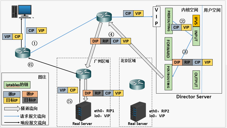
- When the user request arrives at the Director Server, the requested data message will first arrive at the preouting chain in the kernel space. At this time, the source IP of the message is CIP and the target IP is VIP.
- The preouting check finds that the destination IP of the packet is local, and sends the packet to the INPUT chain
- IPVS compares whether the service requested by the packet is a cluster service. If so, encapsulate a layer of IP message at the head of the request message. The encapsulated source IP is DIP and the target IP is RIP. Then it is sent to the POSTROUTING chain. At this time, the source IP is DIP and the destination IP is RIP
- The POSTROUTING chain sends the data packet to the RS according to the latest encapsulated IP message (because there is an additional layer of IP header encapsulated in the outer layer, it can be understood that it is transmitted through the tunnel at this time). At this time, the source IP is DIP and the destination IP is RIP
- After receiving the message, RS finds that it is its own IP address, so it receives the message. After removing the outermost IP, it will find that there is another layer of IP header inside, and the target is its own lo interface VIP. At this time, RS starts to process the request. After processing, it will send it to eth0 network card through lo interface, and then transfer it outward. At this time, the source IP address is VIP and the target IP is CIP
- The response message is finally delivered to the client
5.3.1 LVS Tun model characteristics
- RIP, VIP and DIP are all public network addresses
- The gateway of RS will not and cannot point to DIP
- All request messages pass through the Director Server, but the response message must not pass through the Director Server
- Port mapping is not supported
- RS system must support tunnel
6 LVAS-NAT mode configuration load balancing
6.1 environmental description
| host | IP |
|---|---|
| Director(DR) | 192.168.25.146 |
| RealServer(RS1) | 192.168.25.147 |
| RealServer(RS2) | 192.168.25.148 |
- First, install the apache website service on the two real servers
- Configure the web page file on the Real server to test access
[root@RS2 ~]# echo 192.168.25.148 > /var/www/html/index.html
[root@RS1 ~]# echo 192.168.25.147 > /var/www/html/index.html
6.2 configuring DR
Director shall configure two network cards, DIP and VIP respectively
[root@DR ~]# cat /etc/sysconfig/network-scripts/ifcfg-ens33
TYPE=Ethernet
BOOTPROTO=static
NAME=ens33
DEVICE=ens33
ONBOOT=yes
IPADDR0=192.168.25.146	    #DIP
PREFIX0=24
GATEWAY0=192.168.25.2
IPADDR1=192.168.25.200		 #VIP. In fact, VIP should be public IP
PREFIX1=24

//Restart the network card to make the configuration effective
[root@DR ~]# ifdown ens33;ifup ens33
[root@DR ~]# ip a
1: lo: <LOOPBACK,UP,LOWER_UP> mtu 65536 qdisc noqueue state UNKNOWN group default qlen 1000
    link/loopback 00:00:00:00:00:00 brd 00:00:00:00:00:00
    inet 127.0.0.1/8 scope host lo
       valid_lft forever preferred_lft forever
    inet6 ::1/128 scope host
       valid_lft forever preferred_lft forever
2: ens33: <BROADCAST,MULTICAST,UP,LOWER_UP> mtu 1500 qdisc fq_codel state UP group default qlen 1000
    link/ether 00:0c:29:05:9c:bb brd ff:ff:ff:ff:ff:ff
    inet 192.168.25.146/24 brd 192.168.25.255 scope global noprefixroute ens33
       valid_lft forever preferred_lft forever
    inet 192.168.25.200/24 brd 192.168.25.255 scope global secondary noprefixroute ens33
       valid_lft forever preferred_lft forever
    inet6 fe80::20c:29ff:fe05:9cbb/64 scope link
       valid_lft forever preferred_lft forever
6.3 RS1 configuration RIP
[root@RS1 ~]# cat /etc/sysconfig/network-scripts/ifcfg-ens33
TYPE=Ethernet
BOOTPROTO=static
NAME=ens33
DEVICE=ens33
ONBOOT=yes
IPADDR=192.168.25.147    //RIP
PREFIX=24
GATEWAY=192.168.25.146	#The gateway here should point to DIP

//Restart the network card to make the configuration effective
[root@RS1 ~]# ifdown ens33;ifup  ens33
6.4 RS2 configuration RIP
[root@RS2 ~]# cat /etc/sysconfig/network-scripts/ifcfg-ens33
TYPE=Ethernet
BOOTPROTO=static
NAME=ens33
DEVICE=ens33
ONBOOT=yes
IPADDR=192.168.25.148    //RIP
PREFIX=24
GATEWAY=192.168.25.146	 #Gateway needs to point to DIP
6.5 add and save rules on Director
//Turn on the ip forwarding function of Director
[root@DR ~]# vim /etc/sysctl.conf
net.ipv4.ip_forward = 1    //Append to configuration file

//Reread configuration
[root@DR ~]# sysctl -p
net.ipv4.ip_forward = 1

//Add scheduler
[root@DR ~]# ipvsadm -A -t 192.168.25.200:80 -s rr / / IP pointing to the Internet
[root@DR ~]# ipvsadm -ln
IP Virtual Server version 1.2.1 (size=4096)
Prot LocalAddress:Port Scheduler Flags
  -> RemoteAddress:Port           Forward Weight ActiveConn InActConn
TCP  192.168.25.200:80 rr

//Add RS to scheduler
[root@DR ~]# ipvsadm -a -t 192.168.25.200:80 -r 192.168.25.147:80 -m
[root@DR ~]# ipvsadm -a -t 192.168.25.200:80 -r 192.168.25.148:80 -m
[root@DR ~]# ipvsadm -ln
IP Virtual Server version 1.2.1 (size=4096)
Prot LocalAddress:Port Scheduler Flags
  -> RemoteAddress:Port           Forward Weight ActiveConn InActConn
TCP  192.168.25.200:80 rr
  -> 192.168.25.147:80            Masq    1      0          0
  -> 192.168.25.148:80            Masq    1      0          0

//Save configuration
[root@DR ~]# ipvsadm -Sn > /etc/sysconfig/ipvsadm
[root@DR ~]# cat /etc/sysconfig/ipvsadm
-A -t 192.168.25.200:80 -s rr
-a -t 192.168.25.200:80 -r 192.168.25.147:80 -m -w 1
-a -t 192.168.25.200:80 -r 192.168.25.148:80 -m -w 1
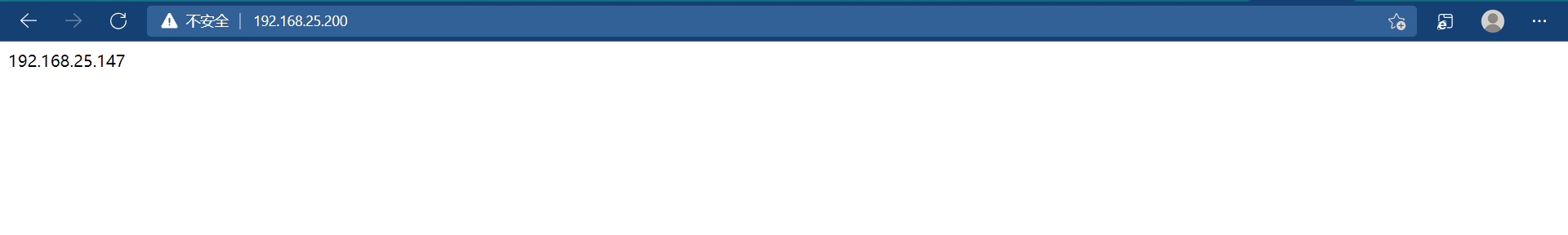
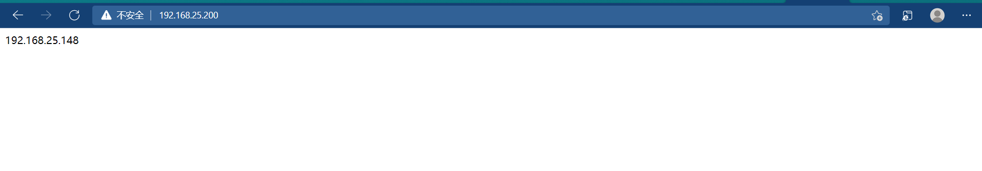
6.6 testing
[root@DR ~]# curl http://192.168.25.200
192.168.25.147
[root@DR ~]# curl http://192.168.25.200
192.168.25.148
[root@DR ~]# curl http://192.168.25.200
192.168.25.147
[root@DR ~]# curl http://192.168.25.200
192.168.25.148
7 LVS-DR mode configuration load balancing
7.1. Experimental environment
Director(DR) : 192.168.25.146 DIP
Director(DR) : 192.168.25.200 VIP
RealServer(RS1) : 192.168.25.147
RealServer(RS2) : 192.168.25.148
- First, install the apache website service on the two real servers
- Configure the web page file on the Real server to test access
[root@RS2 ~]# echo 192.168.25.148 > /var/www/html/index.html
[root@RS1 ~]# echo 192.168.25.147 > /var/www/html/index.html
7.2 turn off firewall and load ip_vs module
[root@DR ~]# systemctl stop firewalld
[root@DR ~]# setenforce 0
[root@DR ~]# modprobe ip_vs
[root@DR ~]# cat /proc/net/ip_vs
IP Virtual Server version 1.2.1 (size=4096)
Prot LocalAddress:Port Scheduler Flags
  -> RemoteAddress:Port Forward Weight ActiveConn InActConn
TCP  C0A819FA:0050 rr
[root@DR ~]# yum -y install ipvsadm
7.3 configuring DR
//Configure the ip address information (dip, vip) of the director
[root@DR ~]# cat /etc/sysconfig/network-scripts/ifcfg-ens33
TYPE=Ethernet
BOOTPROTO=static
NAME=ens33
DEVICE=ens33
ONBOOT=yes
IPADDR0=192.168.25.146	    #DIP
PREFIX0=24
GATEWAY0=192.168.25.2
IPADDR1=192.168.25.200		 #VIP. In fact, VIP should be public IP
PREFIX1=24

//Restart the network card to make the configuration effective
[root@DR ~]# ifdown ens33;ifup ens33


//Add and save rules on Director
[root@DR ~]# ipvsadm -A -t 192.168.25.200:80 -s rr
[root@DR ~]# ipvsadm -a -t 192.168.25.200:80 -r 192.168.25.147:80 -g
[root@DR ~]# ipvsadm -a -t 192.168.25.200:80 -r 192.168.25.148:80 -g
[root@DR ~]# ipvsadm -ln
IP Virtual Server version 1.2.1 (size=4096)
Prot LocalAddress:Port Scheduler Flags
  -> RemoteAddress:Port           Forward Weight ActiveConn InActConn
TCP  192.168.25.200:80 rr
  -> 192.168.25.147:80            Route   1      0          0
  -> 192.168.25.148:80            Route   1      0          0

//Save configuration
[root@DR ~]# ipvsadm -Sn > /etc/sysconfig/ipvsadm
[root@DR ~]# cat /etc/sysconfig/ipvsadm
-A -t 192.168.25.200:80 -s rr
-a -t 192.168.25.200:80 -r 192.168.25.147:80 -g -w 1
-a -t 192.168.25.200:80 -r 192.168.25.148:80 -g -w 1
7.4 configuring RS
//Modify the network card kernel parameters and add the following parameters
[root@RS1 ~]# vim /etc/sysctl.conf
net.ipv4.conf.all.arp_ignore = 1
net.ipv4.conf.all.arp_announce = 2
[root@RS2 ~]# vim /etc/sysctl.conf
net.ipv4.conf.all.arp_ignore = 1
net.ipv4.conf.all.arp_announce = 2

//Reread configuration
[root@RS1 ~]# sysctl -p
net.ipv4.conf.all.arp_ignore = 1
net.ipv4.conf.all.arp_announce = 2
[root@RS2 ~]# sysctl -p
net.ipv4.conf.all.arp_ignore = 1
net.ipv4.conf.all.arp_announce = 2

//RS1 and RS2 need to be configured with RIP. Note: the network card kernel parameters must be modified here before configuring vip, because if vip is configured first, it will be notified to others immediately after vip is configured, and the kernel parameters are modified to avoid notification
[root@RS1 ~]# cat /etc/sysconfig/network-scripts/ifcfg-ens33
TYPE=Ethernet
BOOTPROTO=static
NAME=ens33
DEVICE=ens33
ONBOOT=yes
IPADDR0=192.168.25.147
PREFIX0=24
IPADDR1=192.168.25.200
PREFIX1=32
GATEWAY=192.168.25.2    #Gateway cannot point to DR

[root@RS2 ~]# cat /etc/sysconfig/network-scripts/ifcfg-ens33
TYPE=Ethernet
BOOTPROTO=static
NAME=ens33
DEVICE=ens33
ONBOOT=yes
IPADDR0=192.168.25.148
PREFIX0=24
IPADDR1=192.168.25.200
PREFIX1=32
GATEWAY0=192.168.25.2
7.5 testing