Little love students from the LAN remote control switch?
This is a small project made a few months ago. It was also learned from the big guys. In order to avoid forgetting the process, make a record and share it with the people who need it
The items needed for this project include: Arduino IDE on the computer end, Xiaomi mobile phone Xiaoai schoolmate, blinker on the mobile APP, esp8266nodemcu, and DuPont line breadboard lamp
1. Arduino IDE installs the appropriate version according to my own system. I currently use version 1.8.9
Install esp8266 to expand, here lighting technology provides resources, and small partners need to find official development documents
And download and install the blinker Arduino Library:
Method 1: open the software IDE and search blinker for installation under project loading management library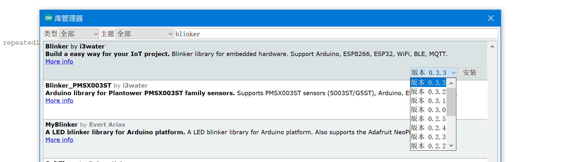
Install the latest version
Method 2: find the official development document of lighting technology and get started with esp8266WiFi access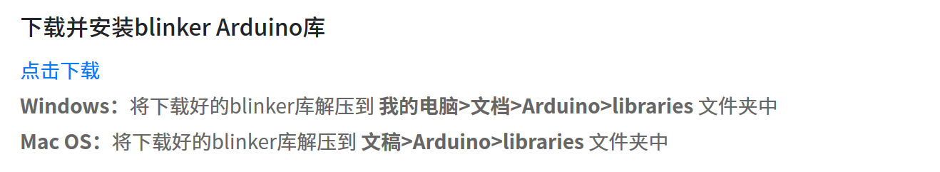
Click download to install as required
So far, the configuration of the computer is complete
2. Mobile APP light Download
In this way, the secret Key is obtained, which will be used in the code
3. Open IDE new file input code
#define BLINKER_WIFI
#Define blinker? MioT? Multi? Outlet / / set to the mode of small love multiple outlets

#include <Blinker.h>
BlinkerButton Button1("btn-km");     //Set the data key name in blinkerapp
BlinkerButton Button2("btn-kckm");   //There are only three of them here
BlinkerButton Button3("btn-gckm");
BlinkerText Text1("text_1");


char i;

char auth[] = "secret key(secret Key)";
char ssid[] = "WiFi name";
char pswd[] = "WiFi password";

bool oState[5] = { false };    //Set 5-way switch control

void miotPowerState(const String & state, uint8_t num)     //Control command of little love students
{
    BLINKER_LOG("need set outlet: ", num, ", power state: ", state);
    if(num==1){
      i=D1;          //Specify the channel interface of each switch corresponding to the development board
    }else if(num==2){
      i=D2;
    }else if(num==3){
      i=D5;
    }

    if (state == BLINKER_CMD_ON) {
        digitalWrite(i, HIGH);      //The control modes here are all inching modes

        BlinkerMIOT.powerState("on", num);
        BlinkerMIOT.print();

        oState[num] = true;

    }
    else if (state == BLINKER_CMD_OFF) {
        digitalWrite(i, LOW);

        BlinkerMIOT.powerState("off", num);
        BlinkerMIOT.print();

        oState[num] = false;

        if (num == 0)
        {
            for (uint8_t o_num = 0; o_num < 5; o_num++)
            {
                oState[o_num] = false;
            }
        }
    }
}

void miotQuery(int32_t queryCode, uint8_t num)
{
    BLINKER_LOG("AliGenie Query outlet: ", num,", codes: ", queryCode);

    switch (queryCode)
    {
        case BLINKER_CMD_QUERY_ALL_NUMBER :
            BLINKER_LOG("MIOT Query All");
            BlinkerMIOT.powerState(oState[num] ? "on" : "off", num);
            BlinkerMIOT.print();
            break;
        case BLINKER_CMD_QUERY_POWERSTATE_NUMBER :
            BLINKER_LOG("MIOT Query Power State");
            BlinkerMIOT.powerState(oState[num] ? "on" : "off", num);
            BlinkerMIOT.print();
            break;
        default :
            BlinkerMIOT.powerState(oState[num] ? "on" : "off", num);
            BlinkerMIOT.print();
            break;
    }
}

void dataRead(const String & data)
{
    BLINKER_LOG("Blinker readString: ", data);

    Blinker.vibrate();

    uint32_t BlinkerTime = millis();

    Blinker.print("millis", BlinkerTime);
}


void button1_callback(const String & state)     //Light on app internal control button triggered
{
    BLINKER_LOG("get button state: ", state);
        digitalWrite(D1, HIGH);
        Blinker.print("Door opening command has been processed");
        Text1.print("shuju");

}

void button2_callback(const String & state)     //Light on app internal control button triggered
{
    BLINKER_LOG("get button state: ", state);
        digitalWrite(D2, HIGH);

}

void button3_callback(const String & state)     //Light on app internal control button triggered
{
    BLINKER_LOG("get button state: ", state);
        digitalWrite(D5, HIGH);

}


void setup()
{
    Serial.begin(115200);
    BLINKER_DEBUG.stream(Serial);

    pinMode(D1, OUTPUT);
    digitalWrite(D1, LOW);
    pinMode(D2, OUTPUT);
    digitalWrite(D2, LOW);
    pinMode(D5, OUTPUT);
    digitalWrite(D5, LOW);


    Blinker.begin(auth, ssid, pswd);
    Blinker.attachData(dataRead);

    BlinkerMIOT.attachPowerState(miotPowerState);
    BlinkerMIOT.attachQuery(miotQuery);
    Button1.attach(button1_callback);
    Button2.attach(button2_callback);
    Button3.attach(button3_callback);
}

void loop()
{
    Blinker.run();
}
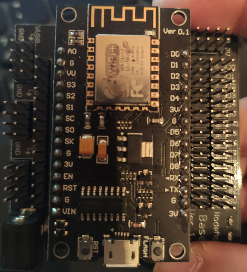
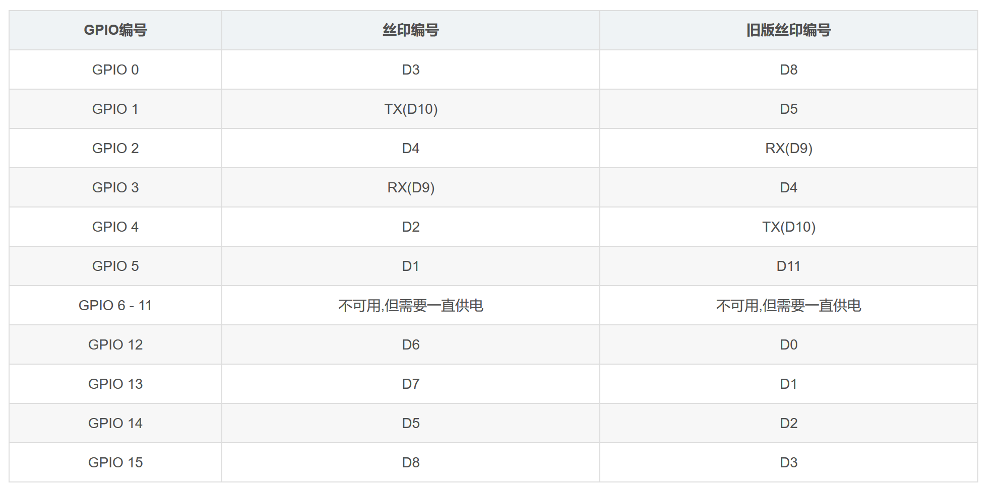
Our esp8266 is so long that three interfaces are mainly used in the code. If there is a foundation, it can be seen that they are D1, D2 and D5. It doesn't matter what we don't understand, mainly in these three areas:
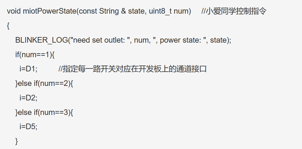
If you need to make small changes, you can use other ports instead. Of course, there are other places in the code that need to be replaced
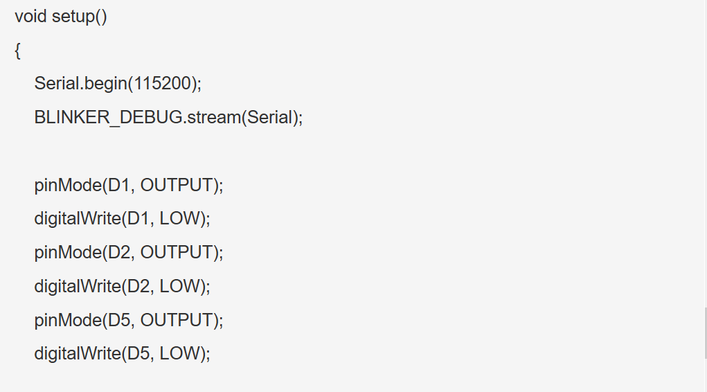
It can be seen from here that after startup, the level of the three ports is low, and the light is not on
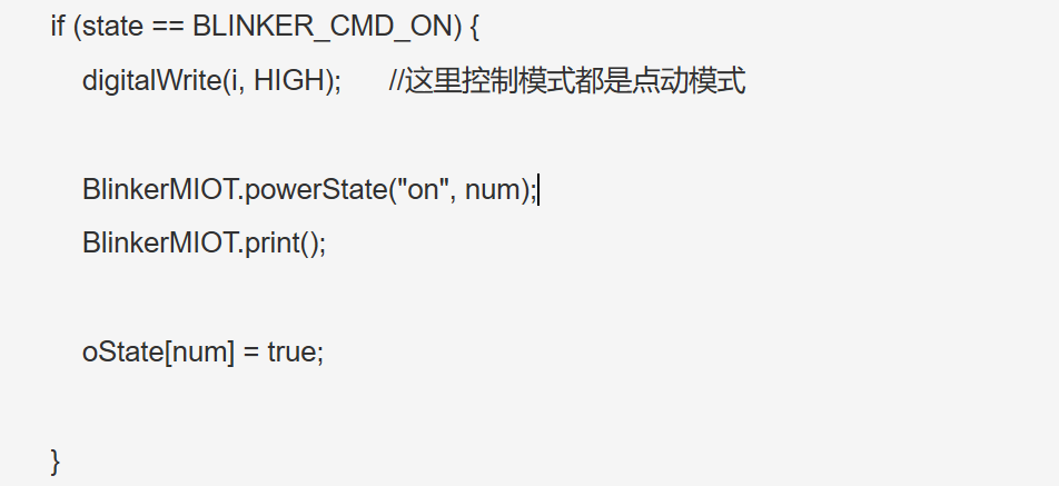
As can be seen here, when xiaoaitong receives the appropriate command, the port outputs high level
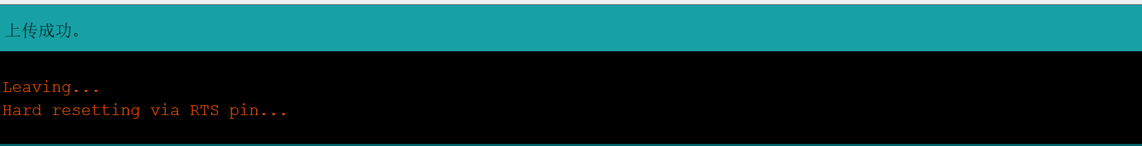
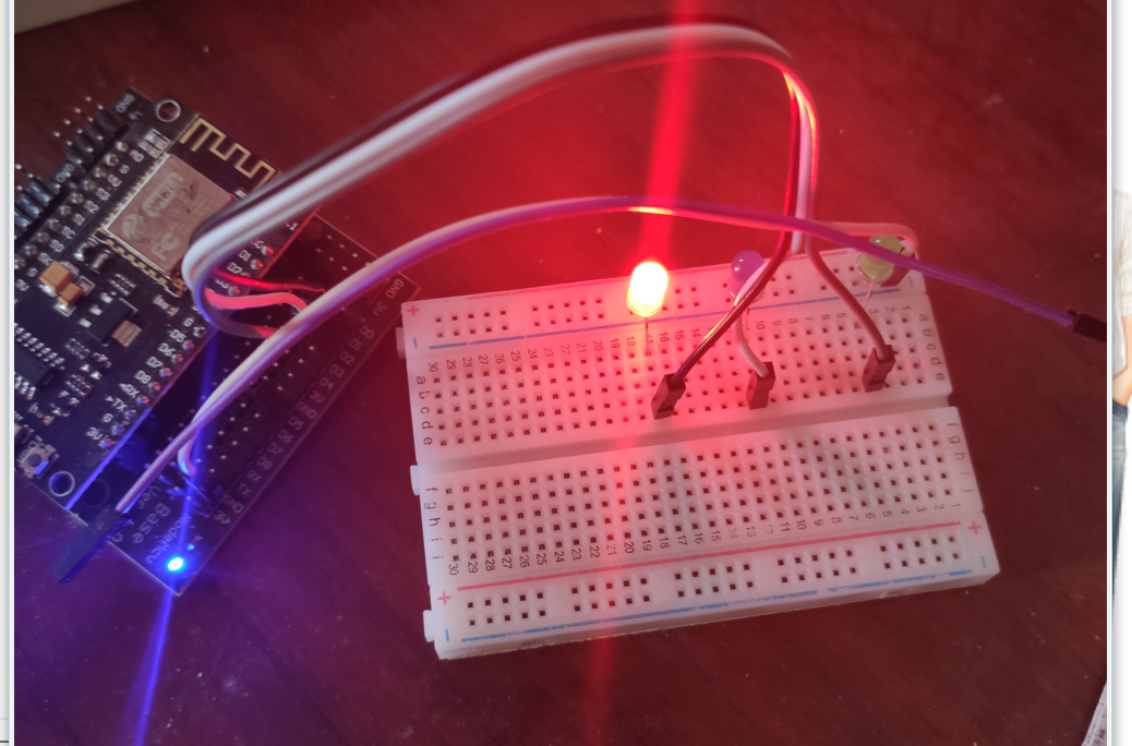
There's no more bullshit. We burn the program and wire it
4. Open IDE and connect to esp8266
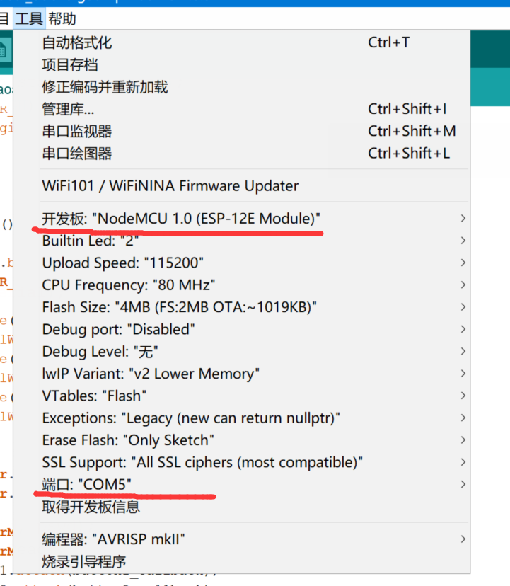
Select the development board and determine the port
Verify on IDE before uploading
 Then connect the hardware:
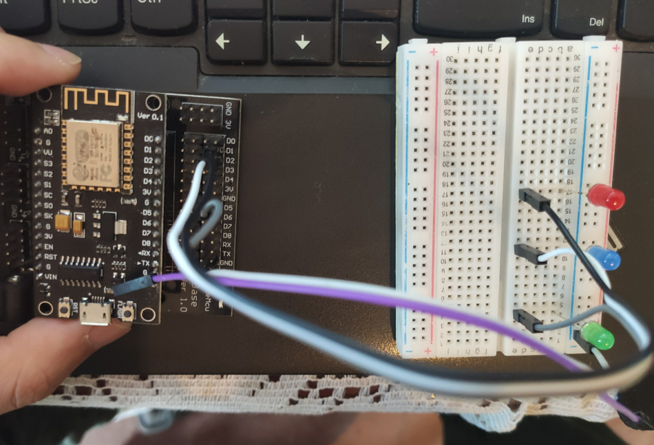
D1 is connected to the positive pole of red light, D2 is connected to the positive pole of blue light, D5 is connected to the positive pole of green light, and the negative poles of three small lights are connected to the GND of development board together
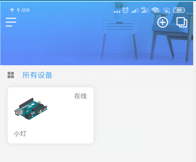
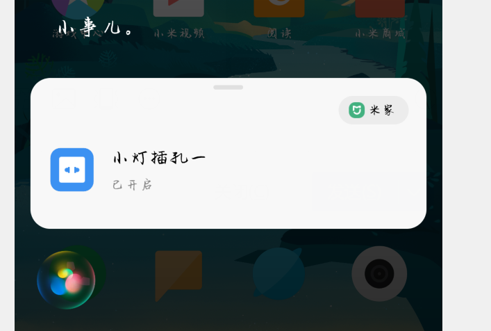
5. Turn on the light on app to see the device online
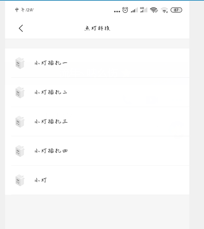
6. When we enter the Mijia APP and add lighting technology and account number in my other platform equipment, we can see that we have five socket switches, the first three of which are our three small light switches:
7. We will enter the new APP training of Xiaoai. If the D1 light bulb is red, we can set what you say to Xiaoai: turn on my red light, Xiaoai's response is device control, choose Xiaolv socket 1, turn on the socket: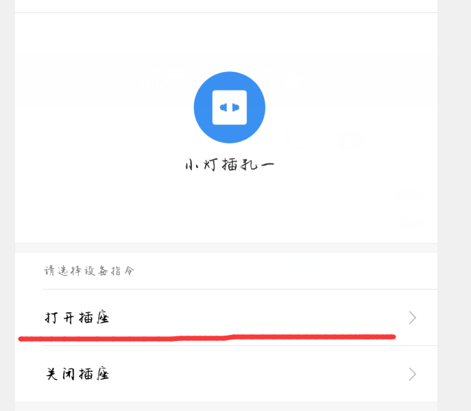
And so on, we have the command to turn on three light bulbs and turn off three light bulbs
Interested partners, come and have a try