Introductory blog:
The use of xilinx FIFO and the discussion of its signals
Simulated Learning of Xilinx ISE FIFO Read-Write Operation
These two blog posts are very good. Two more comprehensive fifo data interface measurement schemes are introduced.
The blogger's own fifo_ip test is conducted below.
Interface code
Here is the code interface for the generated ip core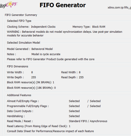
fifo_ip fifotest (
		.rst			(rst), // input rst
		.wr_clk			(wr_clk), // input wr_clk
		.rd_clk			(rd_clk), // input rd_clk
		.din			(din), // input [7 : 0] din
		.wr_en			(wr_en), // input wr_en
		.rd_en			(rd_en), // input rd_en
		.dout			(dout), // output [7 : 0] dout
		.full			(full), // output full
		.almost_full	(almost_full), // output almost_full
		.wr_ack			(wr_ack), // output wr_ack
		.overflow		(overflow), // output overflow
		.empty 			(empty), // output empty
		.almost_empty 	(almost_empty), // output almost_empty
		.valid 			(valid), // output valid
		.underflow 		(underflow), // output underflow
		.rd_data_count 	(rd_data_count), // output [7 : 0] rd_data_count
		.wr_data_count 	(wr_data_count), // output [7 : 0] wr_data_count
		.prog_full 		(prog_full), // output prog_full
		.prog_empty 	(prog_empty) // output prog_empty
);
Interface test
Test code
module ip_test_fifo(
	input clk,
	input rst_n
    );
wire 			rst				;
wire    [7 : 0]	din				;
// wire 			wr_en			;
wire 			rd_en			;
wire  [7 : 0]	dout			;
wire 			full			;
wire 			almost_full		;
wire 			wr_ack			;
wire 			overflow		;
wire 			empty 			;
wire 			almost_empty 	;
wire 			valid 			;
wire 			underflow 		;
wire  [7 : 0]	rd_data_count 	;
wire  [7 : 0]	wr_data_count 	;
wire 			prog_full 		;
wire 			prog_empty 		;
reg [8:0] din_cnt;
always @ (posedge clk or negedge rst_n)
begin
	if(!rst_n)
		din_cnt <= 'd0;
	else
		if(din_cnt == 'd511)
			din_cnt <= 'd0;
		else
			din_cnt <= din_cnt + 1'b1;
end
assign wr_en = ((din_cnt >= 9'd10) && (din_cnt <= 9'd100));
assign rd_en = ((din_cnt >= 9'd110) && (din_cnt <= 9'd200));
assign din = (wr_en) ? din_cnt : 'd0;

assign rst    = ~rst_n ;

fifo_ip fifotest (
		.rst			(rst), // input rst
		.wr_clk			(clk), // input wr_clk
		.rd_clk			(clk), // input rd_clk
		.din			(din), // input [7 : 0] din
		.wr_en			(wr_en), // input wr_en
		.rd_en			(rd_en), // input rd_en
		.dout			(dout), // output [7 : 0] dout
		.full			(full), // output full
		.almost_full	(almost_full), // output almost_full
		.wr_ack			(wr_ack), // output wr_ack
		.overflow		(overflow), // output overflow
		.empty 			(empty), // output empty
		.almost_empty 	(almost_empty), // output almost_empty
		.valid 			(valid), // output valid
		.underflow 		(underflow), // output underflow
		.rd_data_count 	(rd_data_count), // output [7 : 0] rd_data_count
		.wr_data_count 	(wr_data_count), // output [7 : 0] wr_data_count
		.prog_full 		(prog_full), // output prog_full
		.prog_empty 	(prog_empty) // output prog_empty
);

endmodule
test result
It can be seen that
1. wr_ack is used to mark whether the last clock has successfully written data.
2, wr_data_count begins to count after the wr_ack is raised. The count is written to add one successfully and subtracted from one when the data is read, but there is a clock delay.
3. rd_data_count counts the number of data that can be read, and is also the dominant species.
4. Write data while wr_en is elevated. There is no clock delay.
5. When the re_en enabling signal arrives, the data will not come out immediately and will delay a clock cycle.
6. Valid signal is marked read valid. When data comes out, the valid signal is raised.
7. Empty signal
7, A, null signal: (Fig. 3) It can be seen that the signal is related to the count of written data.
7, B, Full Signal: This is not full. Write a test case for testing.
8. Other signals may not be processed (supplemented when testing is required) or see Test 2.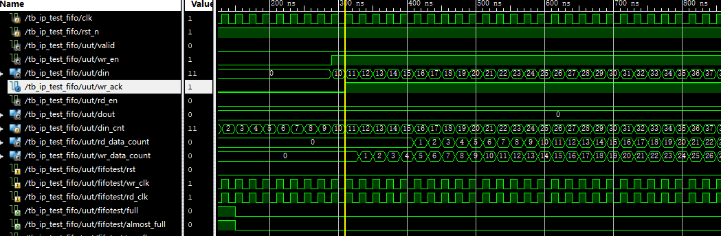
Figure 1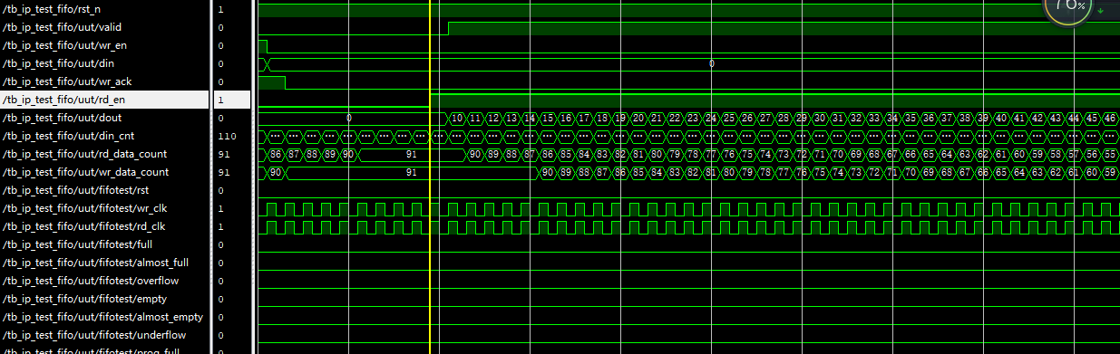
Figure two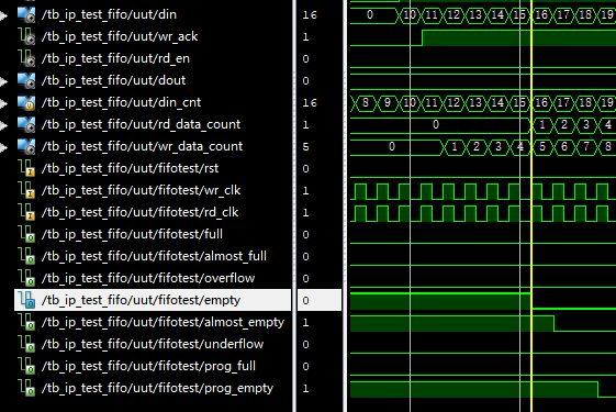
Figure three
Test code
always @ (posedge clk or negedge rst_n)
begin
	if(!rst_n)
		din_cnt <= 'd0;
	else
		if(din_cnt == 'd511)
			din_cnt <= 'd0;
		else
			din_cnt <= din_cnt + 1'b1;
end
assign wr_en = ((din_cnt >= 9'd0) && (din_cnt <= 9'd260));
assign rd_en = ((din_cnt >= 9'd261) && (din_cnt <= 'd511));
// assign din = (wr_en) ? din_cnt : 'd0;
// din = 0;

reg    [7 : 0]	din	= 'd0;
assign rst    = ~rst_n ;
always @ (posedge clk)
begin
	din = ~din;
end
test result
9, rst signal: The reset signal here is high level effective, which is why there is
assign rst = ~rst_n ;
The reason for this piece of code.
10. The validity of the read-enabled signal must be given in one or two clock cycles after the reset, otherwise the data can not be written. There are two ways of checking, first, through the data read later, and second, according to the wr_ack signal.
11. When the full signal is elevated, the data can't be written (Fig. 5, according to wr_ack)
12. Overflow signal: When the data is full, the data is written and the overflow signal is raised.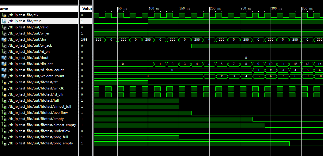
Figure four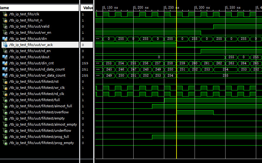
Figure five