In this chapter, we will introduce two aspects: affine transformation and 3D transformation. Then we will introduce solid objects realized by 3D transformation.
1. Radiological transformation
Compared with the following three-dimensional transformation, affine transformation belongs to two-dimensional transformation. CG at the beginning of the function means using the API of Core Graphics, and CGAffine Transform is only effective for two-dimensional transformation.
(1) Introduction
The transformation attribute of UIView is CGAffineTransform type, which is used for rotation, scaling and translation in two-dimensional space. This is because CGAffineTransform is a 3*2 matrix of people who can multiply two-dimensional space vectors such as CGAffineTransform. The transformation attribute of UIView actually encapsulates the transformation of the internal layer.
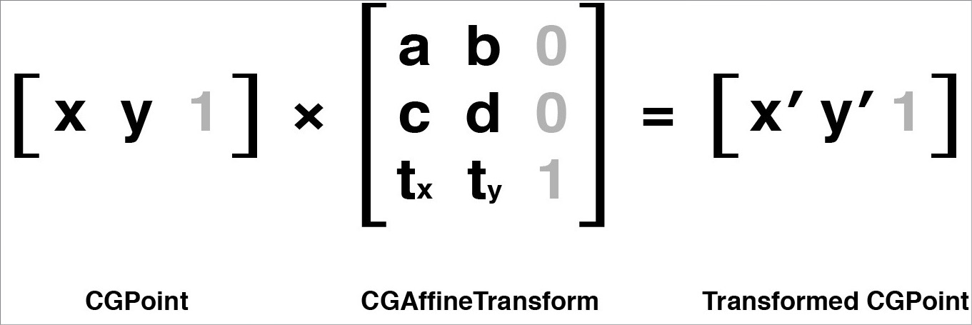
CGAffine Transform and CGPoint in Matrix Representation
The grey values of matrices in pictures are added to allow the matrix to multiply (the number of columns in the left matrix is equal to the number of rows in the right matrix), but they are not actually stored.
Similarly, the transformation matrix is applied to the layer, and each point in the layer is transformed accordingly to form a new quadrilateral. CGAffine Transform affine means that no matter how the transformation is done, the parallel lines in the layer are still parallel after transformation (the feature of affine transformation).
(2) Layer affine
The affine attribute of layer CALayer is affineTransform, which is CGAffineTransform type. transform property corresponding to UIView
(3) Create a CGAffine Transform, that is, create various transformation matrices
Use the following Core Graphics functions to create instances of CGAffineTransform that can be rotated, scaled, and translated.
CGAffineTransformMakeRotation(CGFloat angle)
CGAffineTransformMakeScale(CGFloat sx,CGFloat sy)//Scale the value of a vector
CGAffineTransformMakeTranslation(CGFloat tx,CGFloat ty)//Each point has moved the value specified by the vector.
Note: The transformation function in iOS uses radian.
Macro Definition of Degree Conversion Radius: #define RADIANS_TO_DEGREES(X)((X)/M_PI*180.0)
2. Hybrid transformation
(1) Mixed transformation: Rotation, scaling and translation are mixed together using functions provided by Core Graphics. The essence is that these functions add some transformations on the basis of a CGAffine Transform, and then combine complex transformations.
CGAffineTransformRotate(CGAffineTransform t, CGFloat angle);
CGAffineTransformScale(CGAffineTransform t, CGFloat sx, CGFloat sy);
CGAffineTransformTranslate(CGAffineTransform t, CGFloat tx, CGFloat ty);
(2) General steps
——> First, create a null value of type CGAffineTransform, similar to the unit matrix, using the constant CGAffineTransform Indentity of Core Graphics.
——> Using the following functions, the transformation of the layer is divided into several steps, one step at a time.
CGAffineTransformRotate(CGAffineTransform t, CGFloat angle);
CGAffineTransformScale(CGAffineTransform t, CGFloat sx, CGFloat sy);
CGAffineTransformTranslate(CGAffineTransform t, CGFloat tx, CGFloat ty);
——> If you need to mix two existing transformation matrices, you can use the following method to create new transformations based on the two transformations
CGAffineTransformConcat(CGAffineTransform t1, CGAffineTransform t2);The following example is to scale the layer by 50% and rotate it by 30 degrees.
 //Setting view
    UIView *view = [[UIView alloc]initWithFrame:CGRectMake(kGetViewWidth(self.view)/2, 100, 80, 80)];
    view.backgroundColor = [UIColor orangeColor];
    [self.view addSubview:view];

    //Create a Unit Transform Matrix
    CGAffineTransform transform = CGAffineTransformIdentity;

    //Scale 50%
    transform = CGAffineTransformScale(transform, 0.5, 0.5);

    //Rotate 30 degrees again
    transform = CGAffineTransformRotate(transform, RADIANS_TO_DEGREES(30));

    view.layer.affineTransform = transform;
Results before and after transformation 
3. 3D Transform
(1) Using a series of functions provided by Core Animation, the type is CATransform3D, which is a 4*4 matrix that can be transformed in three-dimensional space. 
Above is a CATransform 3D matrix transformation of a 3D pixel point.
(2) Rotation, scaling and Translation
Core Animation provides some methods for creating and combining CATransform 3D-type matrices, except that the parameters of the functions have an additional z parameter, and the return values of these functions are CATransform 3D-type matrices.
CATransform3DMakeTranslation (CGFloat tx, CGFloat ty, CGFloat tz)

CATransform3DMakeScale (CGFloat sx, CGFloat sy, CGFloat sz)

CATransform3DMakeRotation (CGFloat angle, CGFloat x, CGFloat y, CGFloat z)
(3) The second transformation based on a CATransform 3D, that is, the combination of complex transformations, uses the following functions
 CATransform3DTranslate (CATransform3D t, CGFloat tx, CGFloat ty, CGFloat tz)

CATransform3DScale (CATransform3D t, CGFloat sx, CGFloat sy, CGFloat sz)

CATransform3DRotate (CATransform3D t, CGFloat angle, CGFloat x, CGFloat y, CGFloat z)
(4) Combining two CATransform 3D-type matrices, i.e. combining two transformations
CATransform3D CATransform3DConcat (CATransform3D a, CATransform3D b)Attachment: The positive direction of X, Y, Z axes and the direction of rotation around them. Rotation around the Z axis is equivalent to affine rotation in the previous two-dimensional space, but rotation around the X and Y axis breaks through the two-dimensional space of the screen. 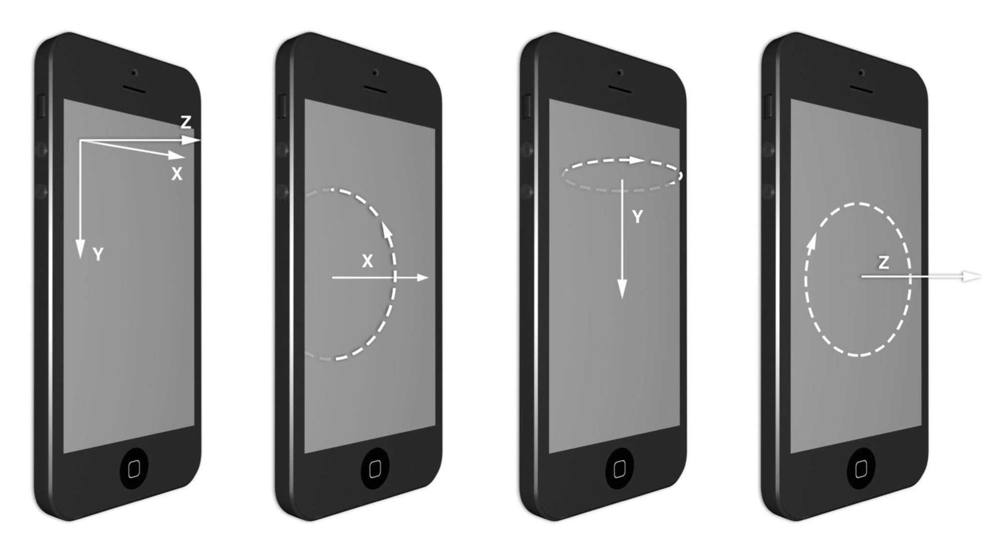
For example, rotate 45 degrees around the Y axis
   //Setting view
    UIView *view = [[UIView alloc]initWithFrame:CGRectMake(kGetViewWidth(self.view)/2-50, 150, 80, 150)];
    [self.view addSubview:view];
    UIImage *image       = [UIImage imageNamed:@"1.jpg"];
    view.layer.contents  = (__bridge id)image.CGImage;

    //Rotate 45 degrees around the Y axis
    CATransform3D transform = CATransform3DMakeRotation(M_PI_4, 0, 1, 0);

    view.layer.transform    = transform;
Result: After rotating, the picture shows narrow, actually breaking through the two-dimensional space, resulting in visual effects.

4. Perspective Projection
In the real world, when objects are far away from us. Because the objects far away from the view angle will look smaller, we use projection Z transformation to modify the matrix.
Core Animation has no function to provide perspective projection. In order to achieve perspective projection, we need to introduce projection transformation (Z transformation) to modify the transformation matrix except rotation. * Because the perspective effect of CATransform 3D is controlled by M34 element in a matrix, so to have perspective effect, we can modify it manually. The value of M34 in the matrix is generally set to - 1.0/d. D represents the distance between the viewing camera and the screen. It is good to set it by oneself. Generally, D is between 500 and 1000. ***m34 is used to scale the values of X and Y proportionally to calculate the distance from the view angle, usually the default value of M34 is 0. 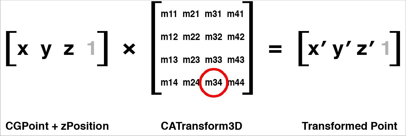
Example: Modify the m34 element of CATransform 3D for perspective
   //Creating Unit juzhen
    CATransform3D transform = CATransform3DIdentity;

    //Using perspective to change the value of m34 of the unit matrix
    transform.m34 = -1.0/50.0;

    //Rotate 45 degrees along the Y axis
    transform = CATransform3DRotate(transform, M_PI_4, 0, 1, 0);

    view.layer.transform = transform;
Result: Before the transformation is the "pre-rotation effect" in the example above. 
Introduce a noun of vanishing point
In perspective drawing, when the object is far from the limit, it becomes a point, so all objects will eventually converge to a point, which is usually the center of the view. So the vanishing point in the application should be the center of the screen or the midpoint of the view containing all the 3D objects. 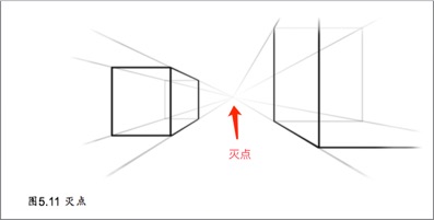
Core Animation fixes the vanishing point on anchor Point of the transformed layer, which changes its vanishing point when changing the position of the layer. So it's important to remember that when you change m34 to produce a 3D effect, you must first place it in the center of the screen, and then move it to the designated position (instead of directly changing its position), so that all the 3D layers share a vanishing point.
5. sublayerTransform property
CALayer's attribute sublayerTransform is a type of CATransform 3D. It affects all sublayers. The advantage is that the containers containing these layers are transformed at one time, so all sublayers automatically inherit this transformation method.
For example, there are many views or layers, each of which needs to be transformed in 3D, so you need to make sure that they share the position in the center of the screen before transforming, and then modify the value of M34 separately. If you use a layer container to contain these views or layers, and then change the container to m34, you can use the sublayer Transform property. It can be changed and applied completely.
Example:
    //Setting Container view
    UIView *view = [[UIView alloc]initWithFrame:CGRectMake(10, 150, kGetViewWidth(self.view)-20, 400)];
    [self.view addSubview:view];


    //Set view1
    UIView *view1 = [[UIView alloc]initWithFrame:CGRectMake(5, 10, kGetViewWidth(self.view)/2-20, 380)];
    [view addSubview:view1];
    UIImage *image        = [UIImage imageNamed:@"1.jpg"];
    view1.layer.contents  = (__bridge id)image.CGImage;


    //Set view2
    UIView *view2 = [[UIView alloc]initWithFrame:CGRectMake(kGetViewWidth(self.view)/2+5, 10, kGetViewWidth(self.view)/2-30,  380)];
    [view addSubview:view2];
    UIImage *image1       = [UIImage imageNamed:@"1.jpg"];
    view2.layer.contents  = (__bridge id)image1.CGImage;


    //Apply perspective to parent layer, that is, layer container
    CATransform3D transform      = CATransform3DIdentity;
    //Change the value of m34 for transform
    transform.m34 = -1.0/250.0;
    view.layer.sublayerTransform = transform;


    //Rotate view1 45 degrees along the y axis
    CATransform3D transform1 = CATransform3DMakeRotation(M_PI_4, 0, 1, 0);
    view1.layer.transform    = transform1;


    //Rotate view2 45 degrees along the y axis
    CATransform3D transform2 = CATransform3DMakeRotation(-M_PI_4, 0, 1, 0);
    view2.layer.transform    = transform2;
Result: 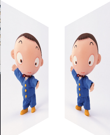
6. Backside
If the angle should be M_PI, you can see the back of the layer, and you can set whether the back of the layer should be drawn by using CALayer's doubleSide property.
7. Flattening Layer
What happens if you reverse the direction of the layer that contains the layer that has been transformed? Is it a little confused? Meaning: Layer A contains Layer B. Rotate Layer A 45 degrees in the positive direction, and then rotate Layer B 45 degrees in the reverse direction. What happens?
If the inner layer is transformed in opposition to the outer layer (in this case around the Z axis), the two transformations will be cancelled out logically.
Example:
 //Layout, two views, view1 and their sub-views view11, view2 and their sub-views view22
    UIView *view1  = [[UIView alloc]initWithFrame:CGRectMake(80, 200, 200,200)];
    UIView *view11 = [[UIView alloc]initWithFrame:CGRectMake(60, 60, 80, 80)];
    view1.backgroundColor  = [UIColor whiteColor];
    view11.backgroundColor = [UIColor lightGrayColor];

    [self.view addSubview:view1];
    [view1 addSubview:view11];

    //view1 outer layer rotates 45 degrees around Z axis
    CATransform3D outerTransform = CATransform3DMakeRotation(M_PI_4, 0, 0, 1);
    view1.layer.transform = outerTransform;

    //view11 Outer Layer Rotates 45 Degrees Around Z Axis
    CATransform3D interTransform = CATransform3DMakeRotation(-M_PI_4, 0, 0, 1);
    view11.layer.transform = interTransform;
Result: 
Rotate around the Y axis.
In the case of 3D, let the inner and outer views rotate around the Y axis, and add perspective; the inner views rotate around the Y axis, and add perspective; according to the above assumption, the inner view 11 should remain unchanged, but the actual result is as follows

This is because although Core Animation layers exist in 3D space, they do not all exist in the same 3D space. The 3D scene of each layer is actually flat. When you look at a layer frontally, you see the imaginary 3D scene actually created by the sublayer. But when you tilt the layer, you will find that the 3D scene is actually only drawn on the surface of the layer.
Similarly, when you're playing a 3D game, you actually tilt the screen once. You may see a wall in front of you in the game, but the tilting screen can't see what's inside the wall. Everything drawn in a scene doesn't change as you look at it from a different angle; the same goes for layers.
This makes it very difficult to create very complex 3D scenes using Core Animation. You can't use a layer tree to create a hierarchical relationship in a 3D structure - any 3D surface in the same scene must be consistent with the same layer, because each parent view flattens its subviews.
At least when you use a normal CALayer, CALayer has a subclass called CATransformLayer to solve this problem. Specific in Chapter 6, "Special Layers" will be discussed in detail.
8. Solid objects
(1) Create a cube
Now try to create a solid-state 3D object (actually a technically so-called hollow object, but it is presented in solid state). We use six separate views to construct all aspects of a cube.
 //Add containnerView
    self.containerView = [[UIView alloc]initWithFrame:CGRectMake(0, 100, kGetViewWidth(self.view), kGetViewWidth(self.view))];
    [self.view addSubview:self.containerView];

    self.faces = [[NSMutableArray alloc]init];
    [self creatFacesArray];


    //Adding perspective to the sublayer of containerView using sublayer Transform
    CATransform3D perspective = CATransform3DIdentity;
    perspective.m34 = -1.0/500.0;


  //Note: After the rotation code is added, it will not be useful on the sublayer Transform applied to the layer.
    self.containerView.layer.sublayerTransform = perspective;

    //Increase cube face 1
    CATransform3D transform = CATransform3DMakeTranslation(0, 0, 100);
    [self addFace:0 withTransform:transform];

    //Increase cube face 2
    transform = CATransform3DMakeTranslation(100, 0, 0);
    transform = CATransform3DRotate(transform, M_PI_2, 0, 1, 0);
    [self addFace:1 withTransform:transform];

    // Increase cube face 3
    transform = CATransform3DMakeTranslation(0, -100, 0);
    transform = CATransform3DRotate(transform, M_PI_2, 1, 0, 0);
    [self addFace:2 withTransform:transform];

    // Increase cube face 4
    transform = CATransform3DMakeTranslation(0, 100, 0);
    transform = CATransform3DRotate(transform, -M_PI_2, 1, 0, 0);
    [self addFace:3 withTransform:transform];

    // Increase cube face 5
    transform = CATransform3DMakeTranslation(-100, 0, 0);
    transform = CATransform3DRotate(transform, -M_PI_2, 0, 1, 0);
    [self addFace:4 withTransform:transform];

    // Increase cube face 6
    transform = CATransform3DMakeTranslation(0, 0, -100);
    transform = CATransform3DRotate(transform, M_PI, 0, 1, 0);
    [self addFace:5 withTransform:transform];
Result:

There's only one side that doesn't show the cube at all, so let's rotate it. However, the cube is made up of six faces, and the normal logic is to rotate the cube, so we have to rotate six faces. We also have another simple method: adjust the sublayer Transform of the container view to rotate the camera, and add two lines of code to the perspectives of the layer of the container view. But keep in mind that the following code must be placed before self.containerView.layer.sublayerTransform = perspective; otherwise, there is no rotation effect.
    //Only one side is displayed, so the hexahedron must be rotated, but six sides must be rotated; adjust the sublayerTransform of the container
    // Rotate 45 degrees around the X-axis
    perspective = CATransform3DRotate(perspective, -M_PI_4, 1, 0, 0);
    // Rotate 45 degrees around the Y axis
    perspective = CATransform3DRotate(perspective, -M_PI_4, 0, 1, 0);
Result

(2) Add light and shadow to the cube
Now it looks more like a cube, but the connection between each side is difficult to distinguish, because there is no shadow and light, it seems very unreal. If you want the cube to look more realistic, you need to make a shadow effect yourself.
Method: It can be adjusted by changing the background color of each face or by directly using a brightened image.
If you want to create a light effect dynamically, you can use different alpha values to make a translucent shadow layer according to the direction of each view. But in order to calculate the opacity of the shadow layer, you need to get the vectors perpendicular to each surface. Then you can calculate the cross-multiplying results of two vectors according to a light source you hypothesized. . Cross-multiplying represents the angle between the light source and the layer, which determines how bright it is.
The following example uses the GLKit framework to calculate vectors (you need to introduce the GLKit library to run the code). The CATransform 3D of each face is converted into GLKMatrix 4, and then a 3*3 rotation matrix is obtained by using the GLKMatrix 4 etMatrix 3 function. This rotation matrix specifies the direction of the layer, and then it can be used to get the values of the vertical and surface vectors.
Try to adjust the values of LIGHT_DIRECTION and AMBEIENT_LIGHT to switch light effects
-(void)applyLightingToFace:(CALayer *)face{

    //Add a Bright Layer
    CALayer *layer = [CALayer layer];
    layer.frame = face.frame;
    [face addSublayer:layer];

    //transform face into GLKMatrix 4 Matrix
    CATransform3D transform = face.transform;
    GLKMatrix4 matrix4 = *(GLKMatrix4 *)&transform;

    //Obtaining 3 x 3 rotation matrix
    GLKMatrix3 matrix3 = GLKMatrix4GetMatrix3(matrix4);

    //Get the value of the surface vector
    GLKVector3 normal = GLKVector3Make(0, 0, 1);
    normal = GLKMatrix3MultiplyVector3(matrix3, normal);
    normal = GLKVector3Normalize(normal);

    //Obtain the cross-product of the direction of light
    GLKVector3 light = GLKVector3Normalize(GLKVector3Make(LIGHT_DIRECTION));
    float dotProduct = GLKVector3DotProduct(light, normal);

    //opacity with bright layers
    CGFloat shadow = 1 + dotProduct - AMBIENT_LIGHT;
    UIColor *color = [UIColor colorWithWhite:0 alpha:shadow];
    layer.backgroundColor = color.CGColor;

}
(3) Click on Events
At present, the cube clicks and does not respond, not because the response events are not processed, but because of the order of views.
As mentioned earlier, the processing of click events is determined by the order of views in the parent view, not the Z-axis order in 3D space. When adding views to cubes, 4, 5, 6 is in front of 3 in view/layer order (because 4, 5, 6 are added later). Even if we can't see the surface of 4, 5, 6 (because it's covered by 1, 2, 3), iOS still keeps its previous order in event response. When trying to click on the button on Surface 3, Surface 4, 5, 6 truncates the click event (depending on the location of the click), which is the same as the normal 2D layout covering the object on the button.
Note: The view you added first is below, because the view you added later is below.
i = 0,UIView.frame={{87.5, 87.5}, {200, 200}}
i = 1,UIView.frame={{287.5, 87.5}, {0, 200}}
i = 2,UIView.frame={{87.5, 87.5}, {200, 0}}
i = 3,UIView.frame={{87.5, 287.5}, {200, 0}}
i = 4,UIView.frame={{87.5, 87.5}, {0, 200}}
i = 5,UIView.frame={{87.5, 87.5}, {200, 200}}
You might think that setting doubleSide to NO solves this problem, because it no longer renders the content behind the view, but it doesn't actually work. Hidden views because of back-to-camera still respond to click events (unlike those hidden by setting hidden properties or alpha to zero, neither way will respond to events). So even if double-sided rendering is banned, it still can't solve this problem (although due to performance problems, it still needs to be set to NO).
   But there are several right solutions:
 1. Set the user Interaction Enabled attribute of all views except Surface 3 to NO to prohibit event passing.
 2. Simply overlay View 3 on View 6 through code.
Knowledge Points:
The hierarchy of the control is related to the order in which you add to the parent view, that is, to add subview to the parent view first. The lower the hierarchy, the more obscured it will be.
The hierarchy of subviews can be changed by the following functions:
//Display UIView at the front:
- (void)bringSubviewToFront:(UIView *)view;
//Display the UIView below:
-(void)sendSubviewToBack:(UIView *)view;
demo
(1) Add the red view 1 to the view, and then add the view 2 to the view, and the result view 2 will override the view 1
  UIView *view1 = [[UIView alloc] initWithFrame:CGRectMake(100, 150, 100, 100)];
    view1.backgroundColor = [UIColor redColor];
    [self.view addSubview:view1];

    UIView *view2 = [[UIView alloc] initWithFrame:CGRectMake(150, 200, 100, 100)];
    view2.backgroundColor = [UIColor greenColor];
    [self.view addSubview:view2];

NSLog(@"self.view.subview=%@",self.view.subviews);
Result: self.view.subview=(
frame = (100 150; 100 100);
frame = (150 200; 100 100);
)

Modify the hierarchy using sendSubviewToBack: and bringSubviewToFront
      // Add the following code to modify the hierarchy
      // Put view2 at the bottom
       [ self.view  sendSubviewToBack: view2];

      // Put view1 at the top
      [  self.view  bringSubviewToFront: view1];

NSLog(@"self.view.subview=%@",self.view.subviews);
Result:
self.view.subview=(
frame = (150 200; 100 100);
frame = (100 150; 100 100);
)

So, the view that is added later will block the view that is added first.