Infrared remote control protocol
Wireless contactless control technology
At present, PWM (pulse width modulation) of NEC Protocol and PPM (pulse position modulation) of Philips RC-5 Protocol are widely used in the coding of infrared remote control
characteristic
Anti interference ability, reliable signal transmission, low power consumption, low cost and easy to realize
appearance

Receiver head: OUT GDN 3.3V
NEC protocol features
① 8-bit address and 8-bit instruction length
② Address and command secondary transmission
③ PWM pulse width modulation represents 0.1 with the duty cycle of transmitting infrared carrier
④ Carrier frequency 38Khz
⑤ Bit time is 1.125ms or 2.25ms (distinguished by high-level duration)
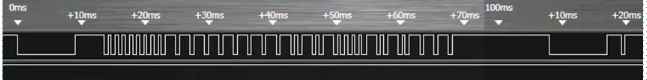
NEC code point definition
One pulse corresponds to 560us continuous carrier. One logic 1 transmission takes 2.25ms and one logic 0 transmission takes 1.125ms
The remote control receiver is at low level when receiving pulse and high level when there is no pulse
Then 1:560us low + 1680us high
2: 560us low + 560us high

NEC remote control command format
The data format is:
Synchronous terminal address code address inverse code control code control inverse code
Synchronization code: 9ms low level + 4.5ms high level
Others are in 8-bit data format
Sequence: low order in front, high order in back
Inverse code can increase transmission reliability
Serial code
9ms low level + 2.5 high level + 0.56 low level + 97.94ms high level
If the key is not released after a frame of data is sent, a duplicate code will be transmitted
Serial code
Hardware connection

Programming ideas
one ️⃣ Start timer input capture default rising edge capture counting frequency 1MHz automatic loading value 10000 overflow time 10ms
two ️⃣ Timer input capture update interrupt capture interrupt capture rising edge generate capture interrupt timer count overflow update interrupt
three ️⃣ When the rising edge is captured, set the falling edge immediately, set the timer count value to 0, and set the bit 4 value of the variable RmtSta to 1 to mark the capture to the rising edge
four ️⃣ The value of the capture falling edge read timer is assigned to the variable Dval, then the capture polarity is set to rising edge capture, and the bit 4 of RmtSta is judged
1: If the rising edge is captured, judge that the Dval 300-800 (560) is 0; 1400-1800 is 1, 2200-2600 indicates continuous transmission, and 4200-4700 indicates synchronization code
five ️⃣ Overflow interrupt occurs in the timer. If the synchronization code is received before and it is the first overflow, the key information collection is completed
Experimental procedure
//initialization
void Remote_Init(void)
{
GPIO_InitTypeDef GPIO_InitStructure;
NVIC_InitTypeDef NVIC_InitStructure;
TIM_TimeBaseInitTypeDef TIM_TimeBaseStructure;
TIM_ICInitTypeDef TIM1_ICInitStructure;
RCC_AHB1PeriphClockCmd(RCC_AHB1Periph_GPIOA, ENABLE);//Enable GPIOA clock
RCC_APB2PeriphClockCmd(RCC_APB2Periph_TIM1, ENABLE);//TIM1 clock enable
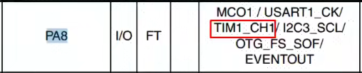
//GPIOA8 multiplex pull-up
GPIO_InitStructure.GPIO_Pin = GPIO_Pin_8;
GPIO_InitStructure.GPIO_Mode = GPIO_Mode_AF;//Performance reuse
GPIO_InitStructure.GPIO_OType = GPIO_OType_PP;//Push pull output
GPIO_InitStructure.GPIO_Speed = GPIO_Speed_100MHz;//100MHz
GPIO_InitStructure.GPIO_PuPd = GPIO_PuPd_UP;//Pull up
GPIO_Init(GPIOA, &GPIO_InitStructure);//initialization
GPIO_PinAFConfig(GPIOA,GPIO_PinSource8,GPIO_AF_TIM1); //GPIOA8 multiplex TIM1
TIM_TimeBaseStructure.TIM_Prescaler=167; Prescaler 1 M Counting frequency
TIM_TimeBaseStructure.TIM_CounterMode=TIM_CounterMode_Up; //Count up
TIM_TimeBaseStructure.TIM_Period=10000; //Set counter auto reload value
TIM_TimeBaseStructure.TIM_ClockDivision=TIM_CKD_DIV1;
TIM_TimeBaseInit(TIM1,&TIM_TimeBaseStructure);
//Initialize TIM2 input capture parameters
TIM1_ICInitStructure.TIM_Channel = TIM_Channel_1; //CC1S=01 Select input IC1 to map on TI1
TIM1_ICInitStructure.TIM_ICPolarity = TIM_ICPolarity_Rising; //Rising edge capture TIM1_ICInitStructure.TIM_ICSelection = TIM_ICSelection_DirectTI; // mapping
TIM1_ICInitStructure.TIM_ICPrescaler = TIM_ICPSC_DIV1; //Configure input frequency division without frequency division
TIM1_ICInitStructure.TIM_ICFilter = 0x03;//IC1F=0003 8 timer clock cycle filtering
TIM_ICInit(TIM1, &TIM1_ICInitStructure);//Initialize timer 2 input capture channel
TIM_ITConfig(TIM1,TIM_IT_Update|TIM_IT_CC1,ENABLE);//Allow update interrupt allow CC1IE capture interrupt
TIM_Cmd(TIM1,ENABLE ); //Enable timer 1
NVIC_InitStructure.NVIC_IRQChannel = TIM1_CC_IRQn;
NVIC_InitStructure.NVIC_IRQChannelPreemptionPriority=1;//Preemption priority 1
NVIC_InitStructure.NVIC_IRQChannelSubPriority =3; //Sub priority 3
NVIC_InitStructure.NVIC_IRQChannelCmd = ENABLE; //IRO channel enable
NVIC_Init(&NVIC_InitStructure); //Initialize NVIC register
NVIC_InitStructure.NVIC_IRQChannel = TIM1_UP_TIM10_IRQn;
NVIC_InitStructure.NVIC_IRQChannelPreemptionPriority=1;//Preemption sub priority 3
NVIC_InitStructure.NVIC_IRQChannelSubPriority =2; //Sub priority 2
NVIC_InitStructure.NVIC_IRQChannelCmd = ENABLE; //IRQ channel enable
NVIC_Init(&NVIC_InitStructure); //Initialize NVIC register
}
//Timer 1 input capture interrupt service routine
void TIM1_CC_IRQHandler(void)
{
if(TIM_GetITStatus(TIM1,TIM_IT_CC1)==SET) //Process Capture (CC1TE) interrupt
{
if(RDATA)//Rising edge capture
{
TIM_OC1PolarityConfig(TIM1,TIM_ICPolarity_Falling); //CC1P=1 set falling edge capture
TIM_SetCounter(TIM1,0); //Clear timer value
RmtSta|=0X10; //The rising edge of the marker has been captured
}else //Falling edge capture
{
Dval=TIM_GetCapture1(TIM1);
TIM_OC1PolarityConfig(TIM1,TIM_ICPolarity_Rising); //CC1P=0 Set rising edge capture
if(RmtSta&0X10) //Complete a high level acquisition
{
if(RmtSta&0X80)//Received boot code
{
if(Dval>300&&Dval<800) //560 standard value, 560us
{
RmtRec<<=1; //Move left one bit
RmtRec|=0; //1 bit received
}else if(Dval>1400&&Dval<1800) //1680 bit standard, 1680us
{
RmtRec<<=1;
RmtRec|=1;
}else if(Dval>2200&&Dval<2600) //Get the key value increase information 2500 as standard 2.5ms
{
RmtCnt++; //The number of keys is increased once
RmtSta&=0XF0; //Clear timer
}
}else if(Dval>4200&&Dval<4700) //4500 is the standard value of 4.5ms
{
RmtSta|=1<<7; //Mark successful boot reception
RmtCnt=0; //Clear key count register
}
}
RmtSta&=~(1<<4);
}
}
TIM_ClearITPendingBit(TIM1,TIM_IT_CC1); //Clear interrupt flag bit
}
//Timer 1 overflow interrupt
void TIM1_UP_TIM10_IRQHandler(void)
{
if(TIM_GetITStatus(TIM1,TIM_IT_Update)==SET) //Overflow interrupt
{
if(RmtSta&0x80)//Last received data
{
RmtSta&=~0X10; //Cancel rising capture flag
if((RmtSta&0X0F)==0X00)RmtSta|=1<<6;//Mark that the key value information collection of one key has been completed
if((RmtSta&0X0F)<14)RmtSta++;
//14 is taken because it is about 90ms at the end of the continuous transmission code. If it overflows more than 13 times, it indicates that the received continuous transmission code has ended and the relevant parameters are cleared
else
{
RmtSta&=~(1<<7);//Clear boot flag
RmtSta&=0XF0; //Clear counter
}
}
}
TIM_ClearITPendingBit(TIM1,TIM_IT_Update); //Clear interrupt flag bit
}
//Processing infrared keyboard
u8 Remote_Scan(void)
{
u8 sta=0;
u8 t1,t2;
if(RmtSta&(1<<6))//Got all the information about a key
{
t1=RmtRec>>24; //Get the address code
t2=(RmtRec>>16)&0xff; //Get address inverse code
if((t1==(u8)~t2)&&t1==REMOTE_ID)//Verify the remote control identification code (ID) and address
{
t1=RmtRec>>8;
t2=RmtRec;
if(t1==(u8)~t2)sta=t1;//The key value is correct
}
if((sta==0)||((RmtSta&0X80)==0))//Key data error / remote control has not been pressed
{
RmtSta&=~(1<<6);//Clear received valid key ID
RmtCnt=0; //Clear key count
}
}
return sta;
}
//Main function
int main(void)
{
u8 key;
u8 t=0;
u8 *str=0;
NVIC_PriorityGroupConfig(NVIC_PriorityGroup_2);//Set system interrupt priority group 2
delay_init(168); //Initialization delay function
uart_init(115200); //Initialization serial port baud rate 115200
LED_Init();
LCD_Init();
Remote_Init();
POINT_COLOR=RED;
LCD_ShowString(30,50,200,16,16,"Explorer STM32F4");
LCD_ShowString(30,70,200,16,16,"REMOTE TEST");
LCD_ShowString(30,90,200,16,16,"ATOM@ALIENTEK");
LCD_ShowString(30,110,200,16,16,"2021/10/10");
LCD_ShowString(30,130,200,16,16,"KEYVAL:");
LCD_ShowString(30,150,200,16,16,"KEYCNT:");
LCD_ShowString(30,170,200,16,16,"SYMBOL:");
while(1)
{
key=Remote_Scan();
if(key)
{
LCD_ShowNum(86,130,key,3,16); //Display key value
LCD_ShowNum(86,150,RmtCnt,3,16); //Displays the number of keystrokes
switch(key)
{
case 0:str="ERROR";break;
case 162:str="POWER";break;
case 98:str="UP";break;
case 2:str="PLAY";break;
case 226:str="ALIENTEK";break;
case 194:str="RIGHT";break;
case 34:str="LEFT";break;
case 224:str="VOL-";break;
case 168:str="DOWN";break;
case 144:str="VOL+";break;
case 104:str="1";break;
case 152:str="2";break;
case 176:str="3";break;
case 48:str="4";break;
case 24:str="5";break;
case 122:str="6";break;
case 16:str="7";break;
case 56:str="8";break;
case 90:str="9";break;
case 66:str="0";break;
case 82:str="DELETE";break;
}
LCD_Fill(86,170,116+8*8,170+16,WHITE); //Clear previous display
LCD_ShowString(86,170,200,16,16,str); //Display SYMBOL
}else delay_ms(10);
t++;
if(t==20)
{
t=0;
LED0=!LED0;
}
}
}