This article uses Italian Semiconductor (ST): STM32F103C8T6 Core Version: ARM Cortex-M3, if not this chip, please refer to the schematic of the chip you are using.
Picture from Walnut Electronics
Pin Definition
In the pin definition of STM32F103C8T6,
PA11 corresponds to CAN_RX
PA12 corresponds to CAN_TX
STM32 CAN Bus Schematic Diagram
| Header 2X2 | Is a jumper terminal (can be deleted) |
|---|---|
| Header 2 | Wiring terminal |
| TJA1050 | High Speed CAN Transceiver |
TJA1050 is the interface between the controller area network (CAN) protocol controller and the physical bus. This device provides differential transmission capability for the bus and differential reception capability for the CAN controller.
TJA1050 is the third generation Philips high speed CAN transceiver after PCA82C250 and PCA82C251. The most important difference is:
- Because of the best match between CANH and CANL output signals, electromagnetic radiation is reduced to improve the performance of nodes when they are not powered on
- No standby mode
- This makes TJA1050 ideal for power-saving nodes in a partial power network
TJA1050: High Speed CAN Transceiver
TJA1050 uses ISO11898 standard which belongs to high-speed communication mode (detailed below)
In the traditional 8051 single-chip computer, there is no internal integrated CAN bus controller, using the external to connect the SJA1000 external controller: STM32 internal integrated controller, external only need to add TJA1050.
CAN Bus Driver Analysis
1.CAN bus header file program
The compilation of C i s divided into four major stages: preprocessing, compilation, assembly, and linking (test.c test.h => test.i => test.s => test.o => test). The #include macro processing in the C file writes all the contents of the H file referenced in C to the C file in the preprocessing stage, and finally generates an.I intermediate file, in which case the contents of the H file are equivalent to being written to the C file.
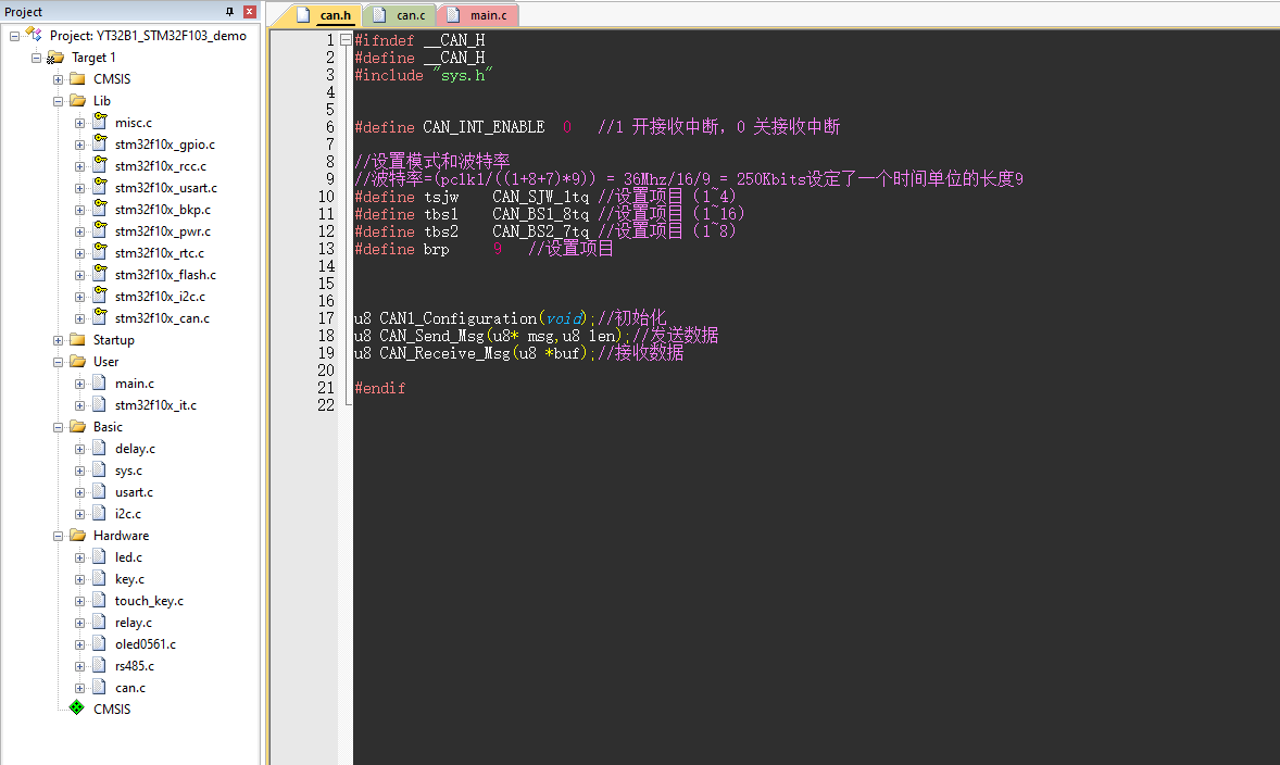
#ifndef __CAN_H
#define __CAN_H
#include "sys.h"


#define CAN_INT_ENABLE	0
// Defines whether to turn on the bus receive mode 1 turn on receive interrupt, 0 turn off receive interrupt

//Set mode and baud rate
//Baud Rate=(pclk1/((1+8+7)*9))= 36Mhz/16/9 = 250Kbits sets a length of 9 for a time unit
//pclk1 clock setting (clock frequency)
#define tsjw CAN_SJW_1tq //Setup project (1~4)
#define tbs1 CAN_BS1_8tq //Setup Items (1~16)
#define tbs2 CAN_BS2_7tq //Setup Item (1~8)
#define brp 9 //Setup Project


u8 CAN1_Configuration(void);//Initialization
u8 CAN_Send_Msg(u8* msg,u8 len);//send data
u8 CAN_Receive_Msg(u8 *buf);//receive data

#endif
2.CAN bus executable
Generally speaking, the compiler does the following processes:
-
Pre-processing stage
-
Lexical and Grammatical Analysis Stage
-
During the compilation phase, pure assembly statements are compiled first, then they are compiled into CPU-related binary code to generate individual target files.
-
Connection phase, absolute address location of each segment of code in each target file, generation of platform-specific executable, compiler is compiled in C file units, that is, if you do not have a C file in your project, then your project will not compile, connector is in target file units, it will have one or more target textPart repositions functions and variables to produce the final executable
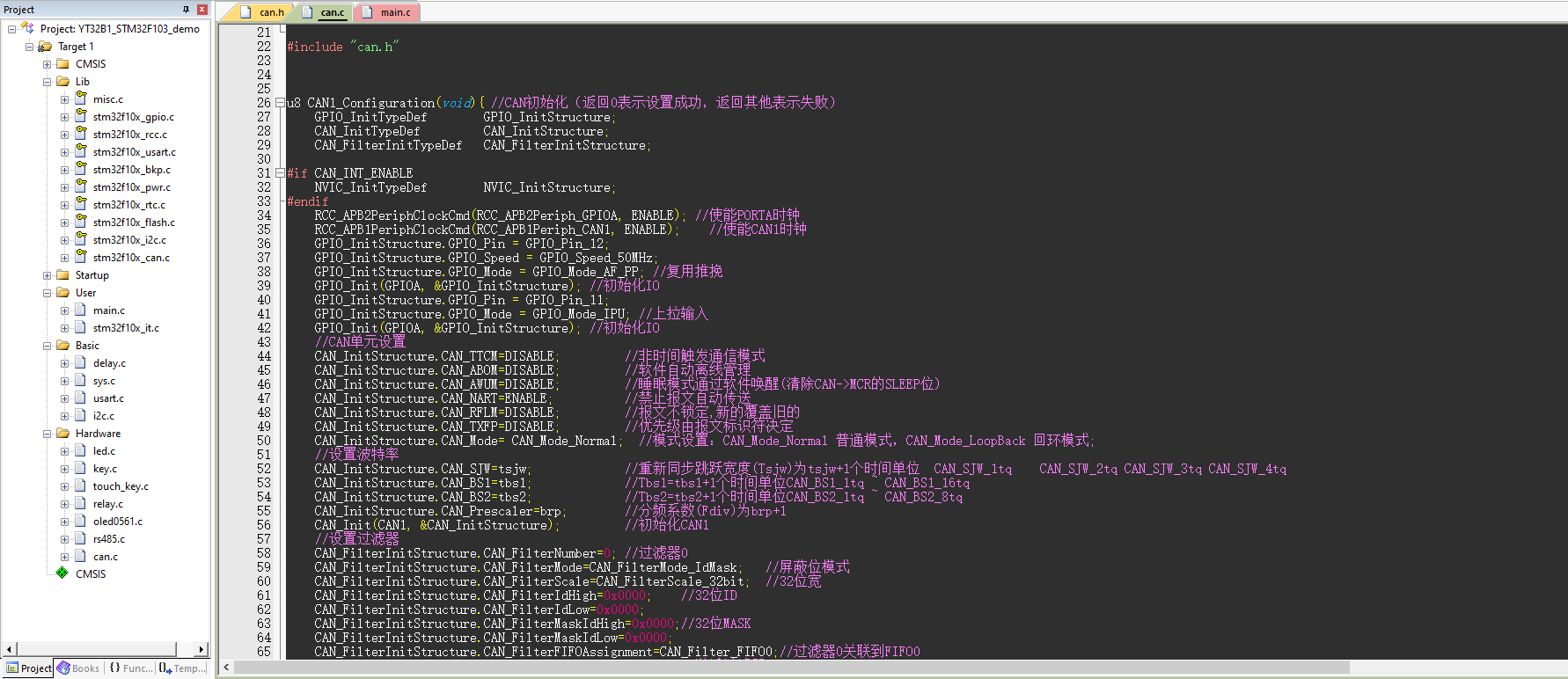
#include "can.h"


u8 CAN1_Configuration(void){ //CAN initialization (returning 0 indicates setup success, returning other indicates failure)
    GPIO_InitTypeDef        GPIO_InitStructure;
    CAN_InitTypeDef         CAN_InitStructure;
    CAN_FilterInitTypeDef   CAN_FilterInitStructure;

#if CAN_INT_ENABLE
    NVIC_InitTypeDef        NVIC_InitStructure;
#endif
    RCC_APB2PeriphClockCmd(RCC_APB2Periph_GPIOA, ENABLE); //Enable PORTA clock
    RCC_APB1PeriphClockCmd(RCC_APB1Periph_CAN1, ENABLE);    //Enable CAN1 clock
	GPIO_InitStructure.GPIO_Pin = GPIO_Pin_12;
	GPIO_InitStructure.GPIO_Speed = GPIO_Speed_50MHz;
	GPIO_InitStructure.GPIO_Mode = GPIO_Mode_AF_PP; //Multiplex push-pull
	GPIO_Init(GPIOA, &GPIO_InitStructure); //Initialize IO
	GPIO_InitStructure.GPIO_Pin = GPIO_Pin_11;
	GPIO_InitStructure.GPIO_Mode = GPIO_Mode_IPU; //Pull Up Input
	GPIO_Init(GPIOA, &GPIO_InitStructure); //Initialize IO
    //CAN Unit Settings
    CAN_InitStructure.CAN_TTCM=DISABLE;         //Non-Time Triggered Communication Mode
    CAN_InitStructure.CAN_ABOM=DISABLE;         //Software automatic offline management
    CAN_InitStructure.CAN_AWUM=DISABLE;         //SLEEP mode via software wake-up (clear SLEP bit for CAN->MCR)
    CAN_InitStructure.CAN_NART=ENABLE;          //Prohibit automatic message transmission
    CAN_InitStructure.CAN_RFLM=DISABLE;         //Message is unlocked, new overwrites old
    CAN_InitStructure.CAN_TXFP=DISABLE;         //Priority is determined by message identifier
    CAN_InitStructure.CAN_Mode= CAN_Mode_Normal;  //Mode settings: CAN_Mode_Normal normal mode, CAN_Mode_LoopBack loopback mode;
    //set baud rate
    CAN_InitStructure.CAN_SJW=tsjw;             //Resynchronization skip width (Tsjw) is tsjw+1 time unit CAN_SJW_1tq CAN_SJW_2tq CAN_SJW_3tq CAN_SJW_4tq
    CAN_InitStructure.CAN_BS1=tbs1;             //Tbs1=tbs1+1 time unit CAN_BS1_1tq~CAN_BS1_16tq
    CAN_InitStructure.CAN_BS2=tbs2;             //Tbs2=tbs2+1 time unit CAN_BS2_1tq~CAN_BS2_8tq
    CAN_InitStructure.CAN_Prescaler=brp;        //The crossover factor (Fdiv) is brp+1
    CAN_Init(CAN1, &CAN_InitStructure);         //Initialize CAN1
	//catalog filter
    CAN_FilterInitStructure.CAN_FilterNumber=0; //Filter 0
    CAN_FilterInitStructure.CAN_FilterMode=CAN_FilterMode_IdMask;   //Shielding Bit Mode
    CAN_FilterInitStructure.CAN_FilterScale=CAN_FilterScale_32bit;  //32 Bit Width
    CAN_FilterInitStructure.CAN_FilterIdHigh=0x0000;    //32-bit ID
    CAN_FilterInitStructure.CAN_FilterIdLow=0x0000;
    CAN_FilterInitStructure.CAN_FilterMaskIdHigh=0x0000;//32-bit MASK
    CAN_FilterInitStructure.CAN_FilterMaskIdLow=0x0000;
    CAN_FilterInitStructure.CAN_FilterFIFOAssignment=CAN_Filter_FIFO0;//Filter 0 is associated with FIFO0
    CAN_FilterInitStructure.CAN_FilterActivation=ENABLE;//Activate filter 0
    CAN_FilterInit(&CAN_FilterInitStructure);           //Filter Initialization

#if CAN_INT_ENABLE //The following are settings for CAN interrupt mode reception
    CAN_ITConfig(CAN1,CAN_IT_FMP0,ENABLE);              //FIFO0 message registration interrupt allowed.
    NVIC_InitStructure.NVIC_IRQChannel = USB_LP_CAN1_RX0_IRQn;
    NVIC_InitStructure.NVIC_IRQChannelPreemptionPriority = 1;     // Primary priority is 1
    NVIC_InitStructure.NVIC_IRQChannelSubPriority = 0;            // Secondary priority is 0
    NVIC_InitStructure.NVIC_IRQChannelCmd = ENABLE;
    NVIC_Init(&NVIC_InitStructure);
#endif
    return 0;
}

//CAN sends a set of data (fixed format: ID 0X12, standard frame, data frame)
//msg: Data pointer, maximum 8 bytes, len: Data length (maximum 8)
//Return value: 0, success;Others, fail;
u8 CAN_Send_Msg(u8* msg,u8 len){
    u8 mbox;
    u16 i=0;
    CanTxMsg TxMessage;
    TxMessage.StdId=0x12;           // Standard Identifier
    TxMessage.ExtId=0x00;           // Set Extended Identifier
    TxMessage.IDE=CAN_Id_Standard;  // Standard Frame
    TxMessage.RTR=CAN_RTR_Data;     // data frame
    TxMessage.DLC=len;              // Length of data to send
    for(i=0;i<len;i++)
    TxMessage.Data[i]=msg[i];       //Write data
    mbox= CAN_Transmit(CAN1,&TxMessage);
    i=0;
    while((CAN_TransmitStatus(CAN1,mbox)==CAN_TxStatus_Failed)&&(i<0XFFF))i++; //Waiting for Send to End
    if(i>=0XFFF)return 1;
    return 0;
}

//can port receive data query
//buf: data cache;
//Return value: 0, no data received, other, received data length;
u8 CAN_Receive_Msg(u8 *buf){
    u32 i;
    CanRxMsg RxMessage;
    if(CAN_MessagePending(CAN1,CAN_FIFO0)==0)return 0;//Quit without receiving data
    CAN_Receive(CAN1,CAN_FIFO0,&RxMessage);//Read data
    for(i=0;i<8;i++) //Put 8 data in parameter array
    buf[i]=RxMessage.Data[i];
    return RxMessage.DLC;  //Number of returned data
}

//Interrupt Receiver for CAN (Interrupt Handler)
//CAN_INT_ENABLE must be 1 in the can.h file to use interrupts
//Data processing should be done as far as possible within the interrupt function, while external processing should stop CAN before processing to prevent data overwriting
void USB_LP_CAN1_RX0_IRQHandler(void){
    CanRxMsg RxMessage;
	vu8 CAN_ReceiveBuff[8]; //CAN bus interrupt acceptance data registers
    vu8 i = 0;
    vu8 u8_RxLen = 0;
  	CAN_ReceiveBuff[0] = 0;	//Empty Register
    RxMessage.StdId = 0x00;
    RxMessage.ExtId = 0x00;
    RxMessage.IDE = 0;
    RxMessage.RTR = 0;
    RxMessage.DLC = 0;
    RxMessage.FMI = 0;
    for(i=0;i<8;i++){
        RxMessage.Data[i]=0x00;
    }
    CAN_Receive(CAN1,CAN_FIFO0,&RxMessage); //Read FIFO0 data
    u8_RxLen = RxMessage.DLC; //Number of read-out data
    if(RxMessage.StdId==0x12){//Determine ID Consistency
		CAN_ReceiveBuff[0] = RxMessage.DLC; //Place the number of received data in Array 0
        for( i=0;i<u8_RxLen; i++){ //Save received data to CAN register
            CAN_ReceiveBuff[i] = RxMessage.Data[i]; //Store 8-bit data in CAN receive register
        }
    }
}

/*
Choose how the IO interface works:
GPIO_Mode_AIN Analog Input
GPIO_Mode_IN_FLOATING Floating Input
GPIO_Mode_IPD Drop-down Input
GPIO_Mode_IPU Pull Up Input
GPIO_Mode_Out_PP push-pull
GPIO_Mode_Out_OD Open-leak output
GPIO_Mode_AF_PP Multiplex push-pull output
GPIO_Mode_AF_OD Multiplex Open-Leak Output
*/
3.CAN Bus Main Function Program
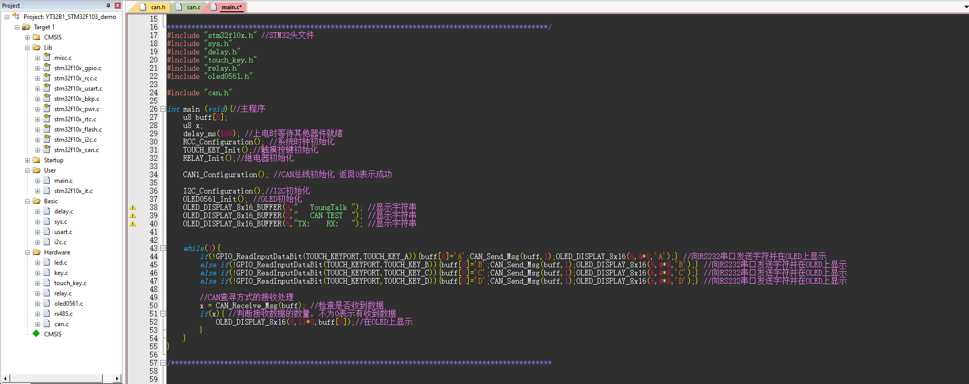
#include "stm32f10x.h" //STM32 header file
#include "sys.h"
#include "delay.h"
#include "touch_key.h"
#include "relay.h"
#include "oled0561.h"

#include "can.h"

int main (void){//main program
	u8 buff[8];
	u8 x;
	delay_ms(100); //Wait for other devices to be ready when power is on
	RCC_Configuration(); //System Clock Initialization
	TOUCH_KEY_Init();//Touch key initialization
	RELAY_Init();//Relay Initialization

	CAN1_Configuration(); //CAN bus initialization returned 0 for success

	I2C_Configuration();//I2C Initialization
	OLED0561_Init(); //OLED Initialization
	OLED_DISPLAY_8x16_BUFFER(0,"   YoungTalk "); //display string
	OLED_DISPLAY_8x16_BUFFER(2,"   CAN TEST  "); //display string
	OLED_DISPLAY_8x16_BUFFER(6,"TX:    RX:   "); //display string


	while(1){
		if(!GPIO_ReadInputDataBit(TOUCH_KEYPORT,TOUCH_KEY_A)){buff[0]='A';CAN_Send_Msg(buff,1);OLED_DISPLAY_8x16(6,4*8,'A');} //Send characters to RS232 serial port and display them on OLED
		else if(!GPIO_ReadInputDataBit(TOUCH_KEYPORT,TOUCH_KEY_B)){buff[0]='B';CAN_Send_Msg(buff,1);OLED_DISPLAY_8x16(6,4*8,'B');} //Send characters to RS232 serial port and display them on OLED
		else if(!GPIO_ReadInputDataBit(TOUCH_KEYPORT,TOUCH_KEY_C)){buff[0]='C';CAN_Send_Msg(buff,1);OLED_DISPLAY_8x16(6,4*8,'C');} //Send characters to RS232 serial port and display them on OLED
		else if(!GPIO_ReadInputDataBit(TOUCH_KEYPORT,TOUCH_KEY_D)){buff[0]='D';CAN_Send_Msg(buff,1);OLED_DISPLAY_8x16(6,4*8,'D');} //Send characters to RS232 serial port and display them on OLED

		//Receive Processing for CAN Lookup Mode
		x = CAN_Receive_Msg(buff); //Check to see if data is received
		if(x){ //Determine the number of received data, not 0 means received data
			OLED_DISPLAY_8x16(6,11*8,buff[0]);//Display on OLED
		}
	}
}
junction