OTA introduction:
The full name of OTA is over the air. In embedded systems, it refers to the online software upgrade of an embedded system. As for MCU system, it is an online update of Firmware for the whole MCU, so it is also called FOTA. DFU is also called Device firmware upgrade. All have the same meaning. OTA is used here.
General MCU generally has no wireless function, so the OTA of MCU is generally used in the system realized by dual chip. The wireless chip receives the OTA file of MCU and transmits it to MCU through serial port or USB to realize the OTA function of MCU.
Standalone bootloader:
The independent boot loader uses the external communication interface (UART/USB) to obtain the application file. Firmware update is a single-stage process, which writes application files directly to flash memory in batches, overwriting existing applications without the participation of the application itself. There is little interaction between the stand-alone boot loader and the application running in flash memory. After the boot loader runs, it receives the firmware update packet containing the new firmware through the physical connection (UART/USB). When the firmware update process starts, the new code overwrites the existing stack and application code. If any errors occur during this process, the application cannot be recovered and the process must be restarted.
Application bootloader:
The application boot loader does not start the firmware update process until the running application completely downloads the update image file. The application boot loader expects the image to be located in external memory accessible to the boot loader or in the main flash memory.
The application boot loader relies on the application to obtain a new firmware image. The application can download this image through the communication interface (UART/USB) and store it in an area called download space (OTA storage). When the new image is downloaded and stored, the application boot loader will be called to verify the new image and copy it from the download space to the application flash address (Application).
Software implementation method:
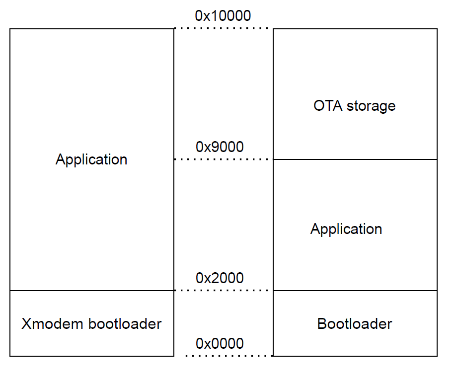
Independent boot loaders mostly use xmodem protocol. Both the wireless module and MCU follow the xmodem protocol (128 byte one time). The wireless module follows the xmodem protocol and transmits the image file through the serial port. The MCU constructs a bootloader that supports the xmodem protocol and writes the received image file to the corresponding flash address.
- Get firmware in Bootloader
- No storage upgrade firmware is required
- During firmware download, the device has no function
- Bootloader directly overwrites the existing application after receiving the upgraded firmware
The application boot loader generally divides the MCU into three parts: bootloader, application and OTA storage. The application program receives the data sent by the wireless module from the communication interface (UART/USB). Each packet received is placed in the OTA storage. When all data are received, the application software restarts, and the operation right is handed over to the bootloader. The bootloader writes the software of the storage worker to the application software area and jumps to the application software operation.
- Upgrade firmware is missing or missing in the application
- The upgraded firmware is stored in internal flash
- Before upgrading, you can verify the integrity and security of the upgraded firmware
- Bootloader reads upgrade firmware from internal flash memory
- During firmware download, the device functions normally
The commonly used ota mode of MCU is Application bootloader
Application Bootloader software operation process:
Application Bootloader core reference code:
#define OFFSET_APPLICATION                       0x2000
#define OFFSET_OTA_STORAGE                       0x9000

uint8_t update_firmware(void)
{
  uint32_t src,obj;
  uint8_t t;
  uint32_t offset;

  src = OFFSET_OTA_STORAGE;
  obj = OFFSET_APPLICATION;

  //31 is the flash size value
  for(t = 0; t < 31; t ++)
  {
    //1024 is the flash page size value, should change according with spicific chip type
    offset = t * 1024;
    if(Read_Flash(value,src + offset,1024) == ERROR)
   {
      return ERROR;
    }

    if(Earse_Flash(obj + offset) == ERROR)
    {
      return ERROR;
    }

    if(Write_Flash(obj + offset,value,1024) == ERROR)
    {
      return ERROR;
    }
  }
}

void main (void)
{
  uint32_t OTA_status_flag;
  uint32_t app_address;

  Read_Flash((unsigned char *)&OTA_status_flag,OTA_FLAG_ADDR,4);

  if(OTA_status_flag == FIREWARE_UPDATE_FLAG)
  {
    if(update_firmware() != SUCCESS)
    {
      Reset();
    }
  }

  app_address = OFFSET_APPLICATION;
  JumpToApp(app_address);

  while(1)
  {
  }
}
Processing flow of application receiving OTA image:
#define OFFSET_APPLICATION                       0x2000
#define OFFSET_OTA_STORAGE                       0x9000
#define FIREWARE_SPECIAL_FLAG                       0x5555AAAA
unsigned char STM32_firm_update_handle(const unsigned char value[],unsigned long position)
{
  unsigned long addr;

  if(ota_Finish_Flag)
  {
    ota_finish_Data = FIREWARE_SPECIAL_FLAG;

    if(Earse_Flash(OTA_FINISH_FLAG) == ERROR)
      return ERROR;

    if(Write_Flash(OTA_FINISH_FLAG,(unsigned char *)&ota_finish_Data,sizeof(ota_finish_Data)) == ERROR)
      return ERROR;

    Reset();
  }
  else
  {
    addr = OFFSET_OTA_STORAGE;

    if(position % 1024 == 0)
    {
      if(Earse_Flash(addr + position) == ERROR)
        return ERROR;
    }

    if(Write_Flash(addr + position,(unsigned char *)value,length) == ERROR)
      return ERROR;
  }

  return SUCCESS;
}
CSDN blog is only used as my notes after work and study, without any commercial purpose. If it infringes your privacy or rights, please feel free to contact the author, and I will delete the relevant content in time.