Because of the need for ADC driver design, I learned about the IIO subsystem driven by Linux. This article is translated from "Linux Device Drivers Development" - - John Madieu. My level is limited. If there are any mistakes, please point out.
IIO Framework
Industrial I/O (IIO) is a core subsystem dedicated to analog-to-digital converter (ADC) and digital-to-analog converter (DAC). As more and more sensors with different code implementations (measurement devices with analog to digital or analog to analog functions) are dispersed on the kernel source, it becomes necessary to collect them. This is what the IIO framework does in a general way. Jonathan Cameron and the Linux-IIO community have been developing it since 2009.

Accelerometers, gyroscopes, current/voltage measurement chips, optical sensors, pressure sensors and so on belong to IIO series devices.
IIO model is based on device and channel architecture:
The device represents the chip itself. It is the top level of the hierarchy.
Channel l represents a single acquisition line of the device. Devices can have one or more channels. For example, an accelerometer is a device with three channels, each of which corresponds to an axis (X, Y and Z).
IIO chips are physical and hardware sensors/converters. It is exposed to user space as a character device (when triggering buffers are supported), as well as sysfs directory entries containing a set of files, some of which represent channels. A single channel is represented by a single sysfs file entry.
The following are two ways to interact with IIO drivers from user space:
L/sys/bus/iio/iio: deviceX/: Represents sensors and their channels
L/dev/iio: deviceX: Character device that represents the export of device events and data buffers
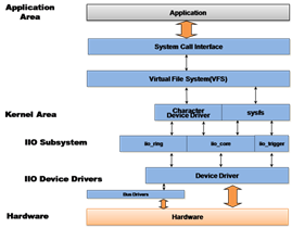
IIO Framework Architecture and Layout
The figure above shows how to organize IIO frameworks between the kernel and user space. Drivers use a set of tools and API s exposed by the IIO core to manage hardware and report to the IIO core for processing. Then, IIO subsystem abstracts the whole underlying mechanism into user space through sysfs interface and character device, on which users can execute system calls.
IIO API s are distributed in multiple header files, as follows:
 #include <linux/iio/iio.h>    /* mandatory */
#include <linux/iio/sysfs.h>  /* mandatory since sysfs is used */
#include <linux/iio/events.h> /* For advanced users, to manage iio events */
#include <linux/iio/buffer.h> /* mandatory to use triggered buffers */
#include <linux/iio/trigger.h>/* Only if you implement trigger in your driver (rarely used)*/
In the following articles, we will describe and deal with each of the concepts of the IIO framework, such as
Traversing its data structures (devices, channels, etc.)
Trigger buffer support and continuous capture, as well as its sysfs interface
Explore existing IIO triggers
Capturing data in single or continuous mode
List available tools to help developers test their devices
(1): IIO data structures: IIO data structures
The IIO device is represented in the kernel as an example of the struct iio_dev structure, which is described by the struct iio_info structure. All important IIO structures are defined in include/linux/iio/iio.h.
Iio_dev structure (iio_dev structure)
This architecture represents IIO devices, describing devices and drivers. It tells us:
l. How many channels are there on the device?
l. In which modes can the device operate: single trigger buffer?
l. Which hooks can this driver use?
struct iio_dev {
   [...]
   int modes;
   int currentmode;
   struct device dev;
   struct iio_buffer *buffer;
   int scan_bytes;
   const unsigned long *available_scan_masks;
   const unsigned long *active_scan_mask;
   bool scan_timestamp;
   struct iio_trigger *trig;
   struct iio_poll_func *pollfunc;
   struct iio_chan_spec const *channels;
   int num_channels;
   const char *name;
   const struct iio_info *info;
   const struct iio_buffer_setup_ops *setup_ops;
   struct cdev chrdev;

};
The complete structure is defined in the IIO header file. We will delete fields that are not of interest here.
Modes: This represents different modes of device support. The supporting models are:
INDIO_DIRECT_MODE represents the sysfs interface provided by the device.
INDIO_BUFFER_TRIGGERED indicates that the device supports hardware triggers. When the trigger buffer is set using the iio_triggered_buffer_setup() function, this mode is automatically added to the device.
INDIO_BUFFER_HARDWARE indicates that the device has a hardware buffer.
INDIO_ALL_BUFFER_MODES is a combination of the above two.
Currtmode: This represents the actua l mode of use of the device.
l dev: This represents the struct device on which IIO devices depend (depending on the Linux device model).
l buffer: This is your data buffer, which is pushed to user space when triggering buffer mode is used. When trigger buffer support is enabled using the iio_triggered_buffer_setup function, it is automatically allocated and associated with your device.
l scan_bytes: This is the number of bytes captured and fed to the buffer. When using trigger buffer from user space, the buffer should be at least indio-> scan_bytes large.
l available_scan_masks: This is an optional array of allowed bit masks. When using trigger buffer, channel capture can be enabled and fed into IIO buffer. If you do not want to allow certain channels to be enabled, you should fill the array with only the allowed channels. Following are examples of scanning masks for accelerometers (with X, Y and Z channels):
/*
 * Bitmasks 0x7 (0b111) and 0 (0b000) are allowed.
 * It means one can enable none or all of them.
 * one can't for example enable only channel X and Y
 */

static const unsigned long my_scan_masks[] = {0x7, 0};
indio_dev->available_scan_masks = my_scan_masks;
l. active_scan_mask: This is the bit mask for enabling channels. Only data from these channels can be pushed into the buffer. For example, for an 8-channel ADC converter, if only the first (0), third (2) and last (7) channels are enabled, the bit mask will be 0b10000101 (0x85). active_scan_mask will be set to 0x85. Then, the driver can use the for_each_set_bit macro to traverse each setting bit, get data according to the channel, and fill the buffer.
l scan_timestamp: This tells us whether to push the capture timestamp into the buffer. If true, the timestamp is used as the last element of the buffer. The timestamp is 8 bytes (64 bits) large.
l. trig: This is the current device trigger (when buffering mode is supported).
Po l lfunc: This is a function that runs on the receiving trigger.
channels: This represents the channel specification structure used to describe each channel a device has.
num_channels: This represents the number of channels specified in the channel.
l. name: This represents the name of the device.
info: Ca l lbacks and persistent information from drivers.
setup_ops: Set of callback functions invoked before and after the buffer is enabled/disabled. This structure is defined in include/linux/iio/iio.h as follows:
struct iio_buffer_setup_ops {
    int (* preenable) (struct iio_dev *);
    int (* postenable) (struct iio_dev *);
    int (* predisable) (struct iio_dev *);
    int (* postdisable) (struct iio_dev *);
    bool (* validate_scan_mask) (struct iio_dev *indio_dev,
                                 const unsigned long *scan_mask);
};
Setup_ops: If not specified, the IIO kernel uses the default iio_triggered_buffer_setup_ops defined in drivers/iio/buffer/industrialio-triggered-buffer.c.
l. chrdev: This is the associated character device created by the IIO core.
The function used to allocate memory for IIO devices is iio_device_alloc():
struct iio_dev * iio_device_alloc(int sizeof_priv)
///struct iio_dev *devm_iio_device_alloc(struct device *dev, int sizeof_priv)
/* Resource-managed iio_device_alloc()*/
/*Managed iio_device_alloc. iio_dev allocated with this function is automatically freed on driver detach.
If an iio_dev allocated with this function needs to be freed separately, devm_iio_device_free() must be used. */
Dev is the device for which iio_dev is allocated, and sizeof_priv is the memory space allocated for any private structure. Thus, it is very simple to transfer the data structure of each device (private). If the allocation fails, the function returns NULL:
 struct iio_dev *indio_dev;
struct my_private_data *data;
indio_dev = iio_device_alloc(sizeof(*data));
if (!indio_dev)
          return -ENOMEM;
/*data is given the address of reserved momory for private data */
data = iio_priv(indio_dev);
After allocating IIO device memory, the next step is to fill in different fields. Upon completion, the iio_device_register function must be used to register the device to the IIO subsystem:
int iio_device_register(struct iio_dev *indio_dev)
       //devm_iio_device_register(dev, indio_dev)
/* Resource-managed iio_device_register() */
After performing this function, the device will be ready to accept requests from user space. The reverse operation (usually done in the release function) is iio_device_unregister():
void iio_device_unregister(struct iio_dev *indio_dev)
// void devm_iio_device_unregister(struct device * dev, struct iio_dev * indio_dev)
Once the registration is cancelled, the memory allocated by iio_device_alloc can be freely released by iio_device_free:
void iio_device_free(struct iio_dev *iio_dev)
// void devm_iio_device_free(struct device * dev, struct iio_dev * iio_dev)
Given IIO devices as parameters, private data can be retrieved in the following ways:
struct my_private_data *the_data = iio_priv(indio_dev);
Iio_info structure: iio_info structure
The struct iio_info structure is used to declare hooks used by the IIO kernel to read/write channel/attribute values:
struct iio_info {
           struct module *driver_module;
            const struct attribute_group *attrs;
            int (*read_raw)(struct iio_dev *indio_dev,
               struct iio_chan_spec const *chan,
               int *val, int *val2, long mask);

            int (*write_raw)(struct iio_dev *indio_dev,

                struct iio_chan_spec const *chan,

                int val, int val2, long mask);
             [...]

};
l driver_module: This is the module structure used to ensure that chrdev has the correct ownership, usually set to THIS_MODULE.
attrs: This represents device attributes.
l read_raw: This is the callback run when the user reads the properties of the device sysfs file. The mask parameter is a bit mask that allows us to know what type of value is requested. The channel parameter lets us know the relevant channels. It can be the sampling frequency used to convert the original value to the ratio of the available value, or the original value itself.
l. write_raw: This is a callback used to write values to the device. For example, it can be used to set the sampling frequency.
The following code shows how to set up the struct iio_info structure:
static const struct iio_info iio_dummy_info = {
    .driver_module = THIS_MODULE,
    .read_raw = &iio_dummy_read_raw,
    .write_raw = &iio_dummy_write_raw,
[...]

/*
 * Provide device type specific interface functions and
 * constant data. Provide device type specific interface functions and constant data.
 */
indio_dev->info = &iio_dummy_info;
IIO channels: IIO channels
The channel represents a single acquisition line. For example, the accelerometer has three channels (X, Y, Z), because each axis represents a single acquisition line. Strct iio_chan_spec represents and describes the structure of a single channel in the kernel:
 struct iio_chan_spec {
        enum iio_chan_type type;
        int channel;
        int channel2;
        unsigned long address;
        int scan_index;
        struct {
            charsign;
            u8 realbits;
            u8 storagebits;
            u8 shift;
            u8 repeat;
            enum iio_endian endianness;
        } scan_type;
        long info_mask_separate;
        long info_mask_shared_by_type;
        long info_mask_shared_by_dir;
        long info_mask_shared_by_all;
        const struct iio_event_spec *event_spec;
        unsigned int num_event_specs;
        const struct iio_chan_spec_ext_info *ext_info;
        const char *extend_name;
        const char *datasheet_name;
        unsigned modified:1;
        unsigned indexed:1;
        unsigned output:1;
        unsigned differential:1;

    };
Meaning of each parameter:
l. type: This specifies the measurement type of the channel. In the case of voltage measurement, it should be IIO_VOLTAGE. For optical sensors, it is IIO_LIGHT. For accelerometers, IIO_ACCEL is used. All available types are defined in include / uapi / linux / iio / types.h, such as enum iio_chan_type. To write drivers for a given converter, look at this file to see the type of channel each belongs to.
Channel: This specifies that. indexed is set to the channel index at 1:00.
channel2: This specifies the channel modification when. modified is set to 1.
l. modified: This specifies whether the modifier is applied to the channel property name. In this case, the modifier is set in. channel 2. For example, IIO_MOD_X, IIO_MOD_Y and IIO_MOD_Z are modifiers for axial sensors on the xyz axis. The list of modifiers available is defined as the enumeration iio_modifier in the kernel IIO header. Modifiers only destroy the channel attribute name in sysfs, not the value.
l indexed: This specifies whether the channel attribute name has an index. If so, specify an index in the. channel field.
l scan_index and scan_type: When using buffer triggers, these fields are used to identify elements in the buffer. Scan_index sets the location of the channel captured in the buffer. Channels with a lower scan_index will be placed before those with a higher index. Setting. scan_index to - 1 prevents the channel from buffer capture (there are no entries in the scan_elements directory).
The channel sysfs attribute exposed to user space is specified in the form of a bit mask. Based on shared information, properties can be set to one of the following masks:
l. info_mask_separate marks attributes as specific to this pass
info_mask_shared_by_type marks this attribute as shared by all channels of the same type. The exported information is shared by all channels of the same type.
info_mask_shared_by_dir marks the attribute as shared by all channels in the same direction. The derived information is shared by all channels in the same direction.
info_mask_shared_by_all marks the attribute as shared by all channels, regardless of their type or direction. The exported information is shared by all channels. Bit masks used to enumerate these attributes are defined in include/linux/iio/iio.h:
enum iio_chan_info_enum {
    IIO_CHAN_INFO_RAW = 0,
    IIO_CHAN_INFO_PROCESSED,
    IIO_CHAN_INFO_SCALE,
    IIO_CHAN_INFO_OFFSET,
    IIO_CHAN_INFO_CALIBSCALE,
    [...]
    IIO_CHAN_INFO_SAMP_FREQ,
    IIO_CHAN_INFO_FREQUENCY,
    IIO_CHAN_INFO_PHASE,
    IIO_CHAN_INFO_HARDWAREGAIN,
    IIO_CHAN_INFO_HYSTERESIS,
    [...]
};
The byte order field should be one of the following:
enum iio_endian {
                         IIO_CPU,
                         IIO_BE,
                         IIO_LE,

};
Channel attribute naming conventions: channel attribute naming conventions
The name of the attribute is automatically generated by the IIO core and has the following pattern: {direction} {type} {index} {modifier} {info_mask}:
The direction direction corresponds to the attribute direction, according to the struct iio_direction structure in drivers/iio/industria l io-core.c:
static const char * const iio_direction[] = {
   [0] = "in",
   [1] = "out",
};
l Type corresponds to the channel type, according to the char array const iio_chan_type_name_spec:
static const char * const iio_chan_type_name_spec[] = {
   [IIO_VOLTAGE] = "voltage",
   [IIO_CURRENT] = "current",
   [IIO_POWER] = "power",
   [IIO_ACCEL] = "accel",
   [...]
   [IIO_UVINDEX] = "uvindex",
   [IIO_ELECTRICALCONDUCTIVITY] = "electricalconductivity",
   [IIO_COUNT] = "count",
   [IIO_INDEX] = "index",
   [IIO_GRAVITY]  = "gravity",
};
The index index mode depends on whether the channel. indexed field is set. If set, the index is fetched from the. channel field to replace the {index} mode.
l The modifier mode depends on the. modified field set by the channel. If set, the modifier will be fetched from the. channel2 field, and the {modifier} mode will be replaced by the char array struct iio_modifier_names structure:
static const char * const iio_modifier_names[] = {
   [IIO_MOD_X] = "x",
   [IIO_MOD_Y] = "y",
   [IIO_MOD_Z] = "z",
   [IIO_MOD_X_AND_Y] = "x&y",
   [IIO_MOD_X_AND_Z] = "x&z",
   [IIO_MOD_Y_AND_Z] = "y&z",
   [...]
   [IIO_MOD_CO2] = "co2",
   [IIO_MOD_VOC] = "voc",
};
info_mask depends on the channel information mask in the char array iio_chan_info_postfix, private or shared index values:
/* relies on pairs of these shared then separate Depends on these shared pairs, and then separates*/
static const char * const iio_chan_info_postfix[] = {
   [IIO_CHAN_INFO_RAW] = "raw",
   [IIO_CHAN_INFO_PROCESSED] = "input",
   [IIO_CHAN_INFO_SCALE] = "scale",
   [IIO_CHAN_INFO_CALIBBIAS] = "calibbias",
   [...]
   [IIO_CHAN_INFO_SAMP_FREQ] = "sampling_frequency",
   [IIO_CHAN_INFO_FREQUENCY] = "frequency",
   [...]
};
Distinguishing channels differentiation
When there are multiple data channels for each channel type, you may encounter problems. The dilemma will be how to identify them. There are two solutions: index and modifier.
Use index: Given an ADC device with a channel line, no index is required. Channels are defined as follows:
static const struct iio_chan_spec adc_channels[] = {
                {
                        .type = IIO_VOLTAGE,
                        .info_mask_separate = BIT(IIO_CHAN_INFO_RAW),

               },
}
The attribute name generated by the channel described above will be in_voltage_raw.
/sys/bus/iio/iio:deviceX/in_voltage_raw
Now let's look at four or even eight channels of converters. How do we identify them? The solution is to use indexes. Setting the. indexed field to 1 will replace the channel attribute name with the. channel value instead of the {index} pattern:
  static const struct iio_chan_spec adc_channels[] = {
        {
                .type = IIO_VOLTAGE,
                .indexed = 1,
                .channel = 0,
                .info_mask_separate = BIT(IIO_CHAN_INFO_RAW),

        },

        {
                .type = IIO_VOLTAGE,
                .indexed = 1,
                .channel = 1,
                .info_mask_separate = BIT(IIO_CHAN_INFO_RAW),
        },
        {
                .type = IIO_VOLTAGE,
                .indexed = 1,
                .channel = 2,
                .info_mask_separate = BIT(IIO_CHAN_INFO_RAW),
        },
        {
                .type = IIO_VOLTAGE,
                .indexed = 1,
                .channel = 3,
                .info_mask_separate = BIT(IIO_CHAN_INFO_RAW),
        },
}
The generated channel attributes are:
 /sys/bus/iio/iio:deviceX/in_voltage0_raw
/sys/bus/iio/iio:deviceX/in_voltage1_raw
/sys/bus/iio/iio:deviceX/in_voltage2_raw
/sys/bus/iio/iio:deviceX/in_voltage3_raw
Use modifiers: Given a light sensor with two channels - one for infrared light, one for infrared and visible light, without an index or modifier, the attribute name will be in_intensity_raw. Using indexes here can be error prone, because using in_intensity0_ir_ray and in_intensity1_ir_ray is meaningless. Using modifiers will help provide meaningful attribute names. Channels are defined as follows:
static const struct iio_chan_spec mylight_channels[] = {

        {
                .type = IIO_INTENSITY,
                .modified = 1,
                .channel2 = IIO_MOD_LIGHT_IR,
                .info_mask_separate = BIT(IIO_CHAN_INFO_RAW),
                .info_mask_shared = BIT(IIO_CHAN_INFO_SAMP_FREQ),
        },
        {
                .type = IIO_INTENSITY,
                .modified = 1,
                .channel2 = IIO_MOD_LIGHT_BOTH,
                .info_mask_separate = BIT(IIO_CHAN_INFO_RAW),
                .info_mask_shared = BIT(IIO_CHAN_INFO_SAMP_FREQ),
        },
        {
                .type = IIO_LIGHT,
                .info_mask_separate = BIT(IIO_CHAN_INFO_PROCESSED),
                .info_mask_shared =BIT(IIO_CHAN_INFO_SAMP_FREQ),

        },
       }
Attribute results:
L/sys/bus/iio/iio: deviceX/in_intensity_ir_ray channel for measuring IR intensity
l/sys/bus/iio/iio: deviceX/in_intensity_both_ray for measuring channels of infrared and visible light
l/sys/bus/iio/iio:deviceX/in_illuminance_input for processed data
l/sys/bus/iio/iio:deviceX/sampling_frequency for sampling frequency, shared by all
This also applies to accelerometers, which we will learn more about in case studies. Now let's summarize what we've discussed so far in virtual IIO drivers.
Summary of Putting it all to get ther
Let's summarize what we've seen so far in a simple virtual drive that exposes four voltage channels. We will ignore read() or write() functions:
#include <linux/init.h>
#include <linux/module.h>
#include <linux/kernel.h>
#include <linux/platform_device.h>
#include <linux/interrupt.h>
#include <linux/of.h>
#include <linux/iio/iio.h>
#include <linux/iio/sysfs.h>
#include <linux/iio/events.h>
#include <linux/iio/buffer.h>


#define FAKE_VOLTAGE_CHANNEL(num)                  \
   {                                               \
         .type = IIO_VOLTAGE,                      \
         .indexed = 1,                             \
         .channel = (num),                         \
         .address = (num),                         \
         .info_mask_separate = BIT(IIO_CHAN_INFO_RAW),   \
         .info_mask_shared_by_type =BIT(IIO_CHAN_INFO_SCALE) \

   }


struct my_private_data {
    int foo;
    int bar;
    struct mutex lock;
};

static int fake_read_raw(struct iio_dev *indio_dev,
                   struct iio_chan_spec const *channel, int *val,
                   int *val2, long mask)
{
    return 0;
}

static int fake_write_raw(struct iio_dev *indio_dev,
                   struct iio_chan_spec const *chan,
                   int val, int val2, long mask)
{
    return 0;
}

static const struct iio_chan_spec fake_channels[] = {
   FAKE_VOLTAGE_CHANNEL(0),
   FAKE_VOLTAGE_CHANNEL(1),
   FAKE_VOLTAGE_CHANNEL(2),
   FAKE_VOLTAGE_CHANNEL(3),

};

static const struct of_device_id iio_dummy_ids[] = {
    { .compatible = "packt,iio-dummy-random", },
    { /* sentinel */ }
};

static const struct iio_info fake_iio_info = {
   .read_raw = fake_read_raw,
   .write_raw        = fake_write_raw,
   .driver_module = THIS_MODULE,
};

static int my_pdrv_probe (struct platform_device *pdev)
{
    struct iio_dev *indio_dev;
    struct my_private_data *data;
   indio_dev = devm_iio_device_alloc(&pdev->dev, sizeof(*data));

   if (!indio_dev) {
         dev_err(&pdev->dev, "iio allocation failed!\n");
         return -ENOMEM;
   }

   data = iio_priv(indio_dev);
   mutex_init(&data->lock);
   indio_dev->dev.parent = &pdev->dev;
   indio_dev->info = &fake_iio_info;
   indio_dev->name = KBUILD_MODNAME;
   indio_dev->modes = INDIO_DIRECT_MODE;
   indio_dev->channels = fake_channels;
   indio_dev->num_channels = ARRAY_SIZE(fake_channels);
   indio_dev->available_scan_masks = 0xF;
    iio_device_register(indio_dev);
    platform_set_drvdata(pdev, indio_dev);
    return 0;
}
static void my_pdrv_remove(struct platform_device *pdev)
{
    struct iio_dev *indio_dev = platform_get_drvdata(pdev);
    iio_device_unregister(indio_dev);
}
static struct platform_driver mypdrv = {
    .probe      = my_pdrv_probe,
    .remove     = my_pdrv_remove,
    .driver     = {
        .name     = "iio-dummy-random",
        .of_match_table = of_match_ptr(iio_dummy_ids),
        .owner    = THIS_MODULE,
    },
};
module_platform_driver(mypdrv);
MODULE_AUTHOR("John Madieu <john.madieu@gmail.com>");
MODULE_LICENSE("GPL");
After loading the above modules, we will have the following output to show that our device really corresponds to our registered platform device:
  ~# ls -l /sys/bus/iio/devices/
lrwxrwxrwx 1 root root 0 Jul 31 20:26 iio:device0 -> ../../../devices/platform/iio-dummy-random.0/iio:device0
lrwxrwxrwx 1 root root 0 Jul 31 20:23 iio_sysfs_trigger -> ../../../devices/iio_sysfs_trigger
The following list shows the channels of the device and their names, which correspond exactly to what we describe in the driver:
 ~# ls /sys/bus/iio/devices/iio\:device0/
dev in_voltage2_raw name uevent
in_voltage0_raw in_voltage3_raw power
in_voltage1_raw in_voltage_scale subsystem
~# cat /sys/bus/iio/devices/iio:device0/name
iio_dummy_random