Development board: mini2440
Kernel: Linux 2.6.32.2
Reference: I2C Video Course for Weidongshan Graduation Class
1. Brief analysis of i2c protocol
i2c midline is a serial bus developed by PHILIPS company, which is used to connect microcontrollers and peripheral devices. It has the following characteristics.There are only two bus lines: a serial data line SDA and a serial clock line SCL.
2. Every device connected to the bus can be determined by software based on its unique address.
3. There is a simple master-slave relationship between devices that transmit data.
4. Host can be used as host sender or host receiver.
5. It is a real multi-host bus. When two or more hosts initiate data transmission at the same time, they can prevent data from being destroyed through conflict detection and arbitration.
6. Serial 8-bit bidirectional transmission, the bit speed can reach 100 kbit/s in standard mode, 400 kbit/s in fast mode and 3.4 Mbit/s in high-speed mode.
7. On-chip filters can increase anti-jamming capability and ensure data integrity.
8. The number of IC s connected to the same bus is limited only by the maximum capacitance of 400Pf.
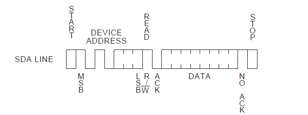
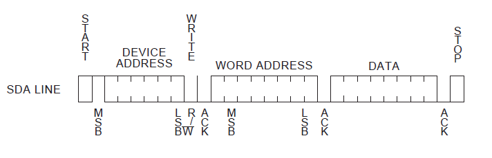
As shown in the figure above, when starting a transmission, the host sends an S signal first and then eight bits of data. The first seven bits of the 8-bit data are slave addresses, and the eighth bit is the direction of transmission (0 is for writing, 1 is for reading). If there is data, it will continue to send, and finally P signal will stop.
Signal type:
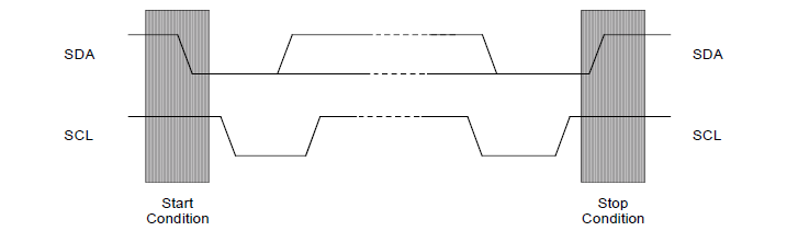
Note: In normal data transmission, SDA changes at low level in SCL and remains stable at high level in SCL.Start signal S signal:
SCL is high level, SDA jumps from high level to low level and begins to transmit data.
End signal P signal:
SCL is high level, SDA jumps from low level to high level and ends data transmission.
Response signal ACK:
After receiving 8 bits of data, the receiver lowers the SDA level in the ninth clock cycle
Note: In the 9th clock cycle, the transmitter keeps the SDA high. If there is an ACK, then the 9th clock cycle SDA is low. If there is no high level, the transmitter can distinguish whether there is an ACK signal according to the level.
If IIC interrupts are enabled, after sending 8 bits of data, the host automatically enters the interrupt processing function, at which time the SCL is pulled down by the sender and the receiver is forced to wait. To recover the transmission, only the interrupt suspension needs to be cleared.
2. s3c2440 read-write process
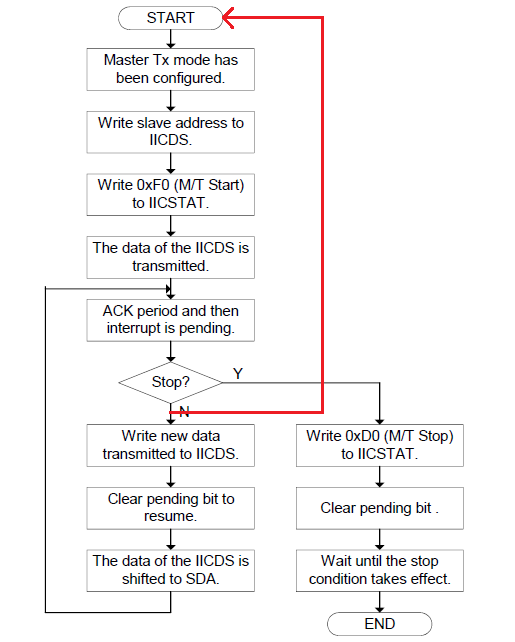
2. Write from slave address to IICDS[7-1], at which time IICDS[7-1] bit represents slave address, and the 0th bit does not care. For example, AT24C08 is 0xA0 (the lowest bit is written 0, which is sent to the back of the 7-bit address on the data line to express sending and receiving. Although writing 0 here, it is not really sent according to 0 here).
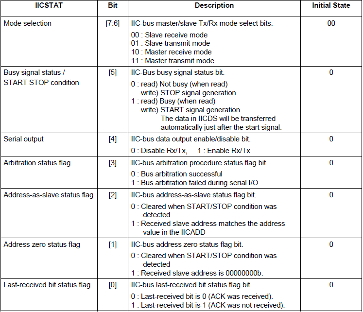
3. Write 0xF0 (Write) or 0xB0 (Read) to IICSTAT register. The two-digit high indicates that the front of the transmission mode has been set. Set IICSTT[5-4] to 11 to enable transmission and send S signals.
4. The IIC controller automatically sends out the IICDS[7-1] set in step 2 and adds the IICDS[0] bit according to the transmission mode.
5. Entering the 9th clock cycle, the slave decides whether to send ACK signal, the host enters interruption, and decides whether to receive ACK signal and whether to continue transmission.
Continue sending:
1. Write data to IICDS
2. Clear interrupt pending, SCL clock recovery, IICDS data automatically sent to SDA line, back to step 5.
Stop sending:
1. Write 0xD0 (Write) and 0x90 (Read) to IICATAT, IICATAT[7-6] is still the transmission mode of representation, IICATAT [5-4]== 0 1, send stop signal
2. Clear interrupt pending, SCL clock recovery, send out stop signal
3. Delay, wait for stop signal to send out
3. Reading and Writing Analysis of AT24C08
1. Writing process
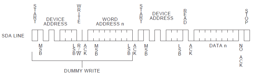
2. Reading process
Attached is a simple bare computer program for reference only: based on MINI2440
- #include <stdio.h>
- #include "s3c2440.h"
- void Delay(int time);
- #define WRDATA (1)
- #define RDDATA (2)
- typedef struct tI2C {
- unsigned char *pData; /* Data Buffer*/
- volatile int DataCount; /* The length of data waiting for transmission*/
- volatile int Status; /* State*/
- volatile int Mode; /* Patterns: Reading/Writing*/
- volatile int Pt; /* pData Location of data to be transmitted*/
- }tS3C24xx_I2C, *ptS3C24xx_I2C;
- static tS3C24xx_I2C g_tS3C24xx_I2C;
- /*
- * I2C Initialization
- */
- void i2c_init(void)
- {
- GPEUP |= 0xc000; //Prohibit internal pull-up
- /*
- * AT24C08 Two wires I2CSCL I2CSDA are connected to 2440 chips
- * Configuration of 2440 GPECON GPE15 GPE14 pins for I2C function
- */
- GPECON |= 0xa0000000; //Selection pin function: GPE15:IICSDA, GPE14:IICSCL
- /* Open INT_IIC interrupt*/
- //INTMSK &= ~(BIT_IIC);
- /* bit[7] = 1, Enabling ACK
- * bit[6] = 0, IICCLK = PCLK/16
- * bit[5] = 1, Enable interruption
- * bit[3:0] = 0xf, Tx clock = IICCLK/16
- * PCLK = 50MHz, IICCLK = 3.125MHz, Tx Clock = 0.195MHz
- */
- IICCON = (1<<7) | (0<<6) | (1<<5) | (0xf); // 0xaf
- //IICADD = 0x10; // S3C24xx slave address = [7:1]
- IICSTAT = 0x10; //I2C Serial Output Enablation (Rx/Tx)
- }
- void I_Write(unsigned int slvaddr, unsigned char addr, unsigned char data)
- {
- unsigned int ack;
- //Write from address
- IICSTAT |= 0x1<<6;//Host Writing Mode
- IICSTAT |= 0x1<<7;
- IICDS = slvaddr;//0xa0; //write slave address to IICDS
- IICCON&=~0x10; //clear pending bit
- IICSTAT = 0xf0; //(M/T start)
- while((IICCON & 1<<4) == 0);//udelay(10);//ack period and then interrupt is pending
- //Write register address.
- IICDS = addr;
- IICCON&=~0x10; //clear pending bit
- while((IICCON & 1<<4) == 0);//udelay(10);//ack period and then interrupt is pending
- //Writing data
- IICDS = data;
- IICCON&=~0x10; //clear pending bit
- while((IICCON & 1<<4) == 0);//udelay(10);//ack period and then interrupt is pending
- //To send a stop signal
- IICSTAT = 0xD0; //write (M/T stop to IICSTAT)
- IICCON&=~0x10; //clear pending bit
- while((IICSTAT & 1<<5) == 1);
- }
- unsigned char I_Read(unsigned int slvaddr, unsigned char addr)
- {
- unsigned char data = 1;
- int ack;
- //Write from address
- IICSTAT |= 0x1<<6;//Host Writing Mode
- IICSTAT |= 0x1<<7;
- slvaddr = 0xA0;
- IICDS = slvaddr;//0xa0; //write slave address to IICDS
- IICCON&=~0x10; //clear pending bit
- IICSTAT = 0xf0; //(M/T start)
- while((IICCON & 1<<4) == 0);//udelay(10);//ack period and then interrupt is pending
- //Write register address
- IICDS = addr;
- IICCON&=~0x10; //clear pending bit
- while((IICCON & 1<<4) == 0);//udelay(10);//ack period and then interrupt is pending
- //Write from address (read mode)
- slvaddr = 0xA1;
- IICSTAT &= ~(0x1<<6);//Host acceptance mode
- IICSTAT |= 0x1<<7;
- IICDS = slvaddr;
- IICCON&=~0x10; //clear pending bit
- IICSTAT = 0xb0; //(M/R Start)
- while((IICCON & 1<<4) == 0);//udelay(10);//uart_SendByte('o');//ack period and then interrupt is pending::
- //Read data
- data = IICDS;
- //IICCON&=~0x10; //clear pending bit
- IICCON = 0x2f; //Clear pending status and set no response
- while((IICCON & 1<<4) == 0);//udelay(10);//ack period and then interrupt is pending
- data = IICDS;
- //IICCON&=~0x10; //clear pending bit
- IICCON = 0x2f; //Clear pending status and set no response
- while((IICCON & 1<<4) == 0);//udelay(10);//ack period and then interrupt is pending
- IICSTAT = 0x90;
- IICCON = 0xaf;
- //IICCON &= ~0x10; //clear pending bit
- while((IICSTAT & 1<<5) == 1);
- return data;
- }
#include <stdio.h>
#include "s3c2440.h"

void Delay(int time);

#define WRDATA      (1)
#define RDDATA      (2)

typedef struct tI2C {
    unsigned char *pData;   /* Data Buffer */
    volatile int DataCount; /* Length of data waiting for transmission */
    volatile int Status;    /* state */
    volatile int Mode;      /* Patterns: Reading/Writing */
    volatile int Pt;        /* pData Location of data to be transmitted */
}tS3C24xx_I2C, *ptS3C24xx_I2C;

static tS3C24xx_I2C g_tS3C24xx_I2C;

/*
 * I2C Initialization
 */
void i2c_init(void)
{
    GPEUP  |= 0xc000;       // No internal pull-up
/*
 *	AT24C08 Two wires I2CSCL I2CSDA are connected to 2440 chips
 *  Configure 2440 GPECON GPE15 GPE14 pin for I2C function
 */
    GPECON |= 0xa0000000;   // Selection pin function: GPE15:IICSDA, GPE14:IICSCL
/* Open INT_IIC interrupt */
    //INTMSK &= ~(BIT_IIC);

    /* bit[7] = 1, Enabling ACK
     * bit[6] = 0, IICCLK = PCLK/16
     * bit[5] = 1, Enable interruption
     * bit[3:0] = 0xf, Tx clock = IICCLK/16
     * PCLK = 50MHz, IICCLK = 3.125MHz, Tx Clock = 0.195MHz
     */
    IICCON = (1<<7) | (0<<6) | (1<<5) | (0xf);  // 0xaf

    //IICADD  = 0x10;     // S3C24xx slave address = [7:1]
    IICSTAT = 0x10;     // I2C Serial Output Enablation (Rx/Tx)
}

void I_Write(unsigned int slvaddr, unsigned char addr, unsigned char data)
{
    unsigned int ack;
	// Write from address
	IICSTAT |= 0x1<<6;//Host Write Mode
    IICSTAT |= 0x1<<7;
    IICDS = slvaddr;//0xa0;  //write slave address to IICDS
    IICCON&=~0x10; //clear pending bit
    IICSTAT = 0xf0;  //(M/T start)
    while((IICCON & 1<<4) == 0);//udelay(10);//ack period and then interrupt is pending
    // Write register address
    IICDS = addr;
    IICCON&=~0x10; //clear pending bit
    while((IICCON & 1<<4) == 0);//udelay(10);//ack period and then interrupt is pending
	// Writing data
    IICDS = data;
    IICCON&=~0x10; //clear pending bit
    while((IICCON & 1<<4) == 0);//udelay(10);//ack period and then interrupt is pending
	// Send out stop signal
    IICSTAT = 0xD0; //write (M/T stop to IICSTAT)
    IICCON&=~0x10; //clear pending bit

    while((IICSTAT & 1<<5) == 1);
}
unsigned char I_Read(unsigned int slvaddr, unsigned char addr)
{
    unsigned char data  = 1;
    int ack;
	// Write from address
	IICSTAT |= 0x1<<6;//Host Write Mode
    IICSTAT |= 0x1<<7;
	slvaddr = 0xA0;
    IICDS = slvaddr;//0xa0;  //write slave address to IICDS
    IICCON&=~0x10; //clear pending bit
    IICSTAT = 0xf0;  //(M/T start)
    while((IICCON & 1<<4) == 0);//udelay(10);//ack period and then interrupt is pending

    // Write register address
    IICDS = addr;
    IICCON&=~0x10; //clear pending bit
    while((IICCON & 1<<4) == 0);//udelay(10);//ack period and then interrupt is pending

    // Write from address (read mode)
    slvaddr = 0xA1;
    IICSTAT &= ~(0x1<<6);//Host acceptance mode
    IICSTAT |= 0x1<<7;
    IICDS = slvaddr;
    IICCON&=~0x10; //clear pending bit
    IICSTAT = 0xb0;  //(M/R Start)
    while((IICCON & 1<<4) == 0);//udelay(10);//uart_SendByte('o');//ack period and then interrupt is pending::

	// Read data
    data = IICDS;
    //IICCON&=~0x10; //clear pending bit
	IICCON = 0x2f;	//Clear pending status and set no response
    while((IICCON & 1<<4) == 0);//udelay(10);//ack period and then interrupt is pending
    data = IICDS;

	//IICCON&=~0x10; //clear pending bit
	IICCON = 0x2f;	//Clear pending status and set no response
    while((IICCON & 1<<4) == 0);//udelay(10);//ack period and then interrupt is pending


    IICSTAT = 0x90;
	IICCON = 0xaf;
    //IICCON &= ~0x10; //clear pending bit

    while((IICSTAT & 1<<5) == 1);

    return data;

}
4. adapter driver
Here, we mainly analyze the core sending algorithm in the driver. As for registration interrupt, IO memory mapping, setting registers are not discussed.
static int xxx_i2c_xfer(struct i2c_adapter *adpap, struct i2c_msg *msg,int num)
The function of this algorithm is to parse some i2c_msg encapsulated in the upper layer, write the data to the register and send it out. In the device driver layer, we use functions like i2c_smbus_write_byte. There are many similar functions. Their function is to encapsulate i2c_msg structure (for example, reading and writing msgs are definitely different, reading a byte and reading multiple bytes are different), and then call i2c_smbus_xfer_emulated - > i2c_transfer, and finally call our x xxx_i2c_xfer function for transmission. By analyzing the i2c_smbus_xfer_emulated function, we can understand how i2c_msg is encapsulated. Next, let's briefly analyze what the top layer wants to do, so that we can know what the bottom functions are not.
- struct i2c_msg {
- __u16 addr; //Slave address
- __u16 flags;
- __u16 len; //How many bytes are there in buf
- __u8 *buf; //The data contained in this msg may be one byte or multiple bytes
- };
struct i2c_msg {
	__u16 addr;		//Slave address
	__u16 flags;
	__u16 len;		// How many bytes are there in buf
	__u8 *buf;		// The data contained in this msg may be one byte or multiple bytes
};
This function omitted a lot of content, just for example ~, see the source code for details.
- static s32 i2c_smbus_xfer_emulated(struct i2c_adapter * adapter, u16 addr,
- unsigned short flags,
- char read_write, u8 command, int size,
- union i2c_smbus_data * data)
- {
- unsigned char msgbuf0[I2C_SMBUS_BLOCK_MAX+3];
- unsigned char msgbuf1[I2C_SMBUS_BLOCK_MAX+2];
- int num = read_write == I2C_SMBUS_READ?2:1; //Write operation, two Msg read operation and one msg. This is consistent with our previous analysis of AT24c08
- struct i2c_msg msg[2] = { { addr, flags, 1, msgbuf0 },
- { addr, flags | I2C_M_RD, 0, msgbuf1 }
- };
- msgbuf0[0] = command; //Moving one bit from the machine address to the right, for example, AT24C08 is 0x50
- switch(size) {
- case I2C_SMBUS_BYTE_DATA: //Single-byte read-write
- if (read_write == I2C_SMBUS_READ)
- msg[1].len = 1;
- /*
- * Read:
- * msgbuf0[0] = command
- * msg[1].len = 1 ,The data will be read in msgbuf0[1].
- */
- else {
- msg[0].len = 2;
- msgbuf0[1] = data->byte;
- /*
- * Write:
- * msgbuf0[0] = command
- * msgbuf0[1] = data->byte
- */
- }
- break;
- }
- status = i2c_transfer(adapter, msg, num);
- }
static s32 i2c_smbus_xfer_emulated(struct i2c_adapter * adapter, u16 addr,
                                   unsigned short flags,
                                   char read_write, u8 command, int size,
                                   union i2c_smbus_data * data)
{
	unsigned char msgbuf0[I2C_SMBUS_BLOCK_MAX+3];
	unsigned char msgbuf1[I2C_SMBUS_BLOCK_MAX+2];
	int num = read_write == I2C_SMBUS_READ?2:1;	// Write two Msg read operations and one msg, which is consistent with our previous analysis of AT24c08
	struct i2c_msg msg[2] = { { addr, flags, 1, msgbuf0 },
	                          { addr, flags | I2C_M_RD, 0, msgbuf1 }
	                        };
	msgbuf0[0] = command;	// Move one bit from the machine address to the right. For example, AT24C08 is 0x50.
	switch(size) {
	case I2C_SMBUS_BYTE_DATA:	// Single byte read-write
		if (read_write == I2C_SMBUS_READ)
			msg[1].len = 1;
			/*
			 * Read:
			 *	msgbuf0[0] = command
			 *  msg[1].len = 1	,The data will be read in msgbuf0[1]
			 */
		else {
			msg[0].len = 2;
			msgbuf0[1] = data->byte;
			/*
			 * Write:
			 *	msgbuf0[0] = command
			 *	msgbuf0[1] = data->byte
			 */
		}
		break;
	}
	status = i2c_transfer(adapter, msg, num);
}Before looking at the adapter program, let's think about it briefly. After sending out the S start signal, there may be three situations as follows:
Current msg.len
== 0, if there is an ACK that sends a stop signal directly. This happens when the controller enumerates devices because it only sends S signals and device addresses, not data.
2. According to MSG - > flags
For judging reading and writing of information such as I2C_M_RD, the lowest bit of MSG - > flags is 1 for reading and the lowest bit is 0 for writing.
#define I2C_M_TEN0x0010
/* this is a ten bit chip address */
#define I2C_M_RD0x0001
/* read data, from slave to master */
#define I2C_M_NOSTART0x4000
/* if I2C_FUNC_PROTOCOL_MANGLING */
#define I2C_M_REV_DIR_ADDR0x2000 /*
if I2C_FUNC_PROTOCOL_MANGLING */
#define I2C_M_IGNORE_NAK0x1000
/* if I2C_FUNC_PROTOCOL_MANGLING */
#define I2C_M_NO_RD_ACK0x0800
/* if I2C_FUNC_PROTOCOL_MANGLING */
#define I2C_M_RECV_LEN0x0400
/* length will be first received byte */
2.1
If it is read
Restore IIC transmission, start reading, take out register data in the next interrupt, if it is the last data to read, can not send ACK (disable ACK).
2.2 If it is written
Write the data into the IICDS register to restore the IIC transmission.
Attached is Mr. Wei Dongshan's procedure:
Before looking at the program, a general flow chart is helpful for understanding the program.
- #include <linux/kernel.h>
- #include <linux/module.h>
- #include <linux/i2c.h>
- #include <linux/init.h>
- #include <linux/time.h>
- #include <linux/interrupt.h>
- #include <linux/delay.h>
- #include <linux/errno.h>
- #include <linux/err.h>
- #include <linux/platform_device.h>
- #include <linux/pm_runtime.h>
- #include <linux/clk.h>
- #include <linux/cpufreq.h>
- #include <linux/slab.h>
- #include <linux/io.h>
- #include <linux/of_i2c.h>
- #include <linux/of_gpio.h>
- #include <plat/gpio-cfg.h>
- #include <mach/regs-gpio.h>
- #include <asm/irq.h>
- #include <plat/regs-iic.h>
- #include <plat/iic.h>
- //#define PRINTK printk
- #define PRINTK(...)
- enum s3c24xx_i2c_state {
- STATE_IDLE,
- STATE_START,
- STATE_READ,
- STATE_WRITE,
- STATE_STOP
- };
- struct s3c2440_i2c_regs {
- unsigned int iiccon;
- unsigned int iicstat;
- unsigned int iicadd;
- unsigned int iicds;
- unsigned int iiclc;
- };
- struct s3c2440_i2c_xfer_data {
- struct i2c_msg *msgs;
- int msn_num;
- int cur_msg;
- int cur_ptr;
- int state;
- int err;
- wait_queue_head_t wait;
- };
- static struct s3c2440_i2c_xfer_data s3c2440_i2c_xfer_data;
- static struct s3c2440_i2c_regs *s3c2440_i2c_regs;
- static void s3c2440_i2c_start(void)
- {
- s3c2440_i2c_xfer_data.state = STATE_START;
- if (s3c2440_i2c_xfer_data.msgs->flags & I2C_M_RD) /* Read*/
- {
- s3c2440_i2c_regs->iicds = s3c2440_i2c_xfer_data.msgs->addr << 1;
- s3c2440_i2c_regs->iicstat = 0xb0; //Host receives, starts
- }
- else /* Write*/
- {
- s3c2440_i2c_regs->iicds = s3c2440_i2c_xfer_data.msgs->addr << 1;
- s3c2440_i2c_regs->iicstat = 0xf0; //Host Send, Start
- }
- }
- static void s3c2440_i2c_stop(int err)
- {
- s3c2440_i2c_xfer_data.state = STATE_STOP;
- s3c2440_i2c_xfer_data.err = err;
- PRINTK("STATE_STOP, err = %d\n", err);
- if (s3c2440_i2c_xfer_data.msgs->flags & I2C_M_RD) /* Read*/
- {
- //The following two lines resume the I2C operation and send out the P signal
- s3c2440_i2c_regs->iicstat = 0x90;
- s3c2440_i2c_regs->iiccon = 0xaf;
- ndelay(50); //Wait for a period of time so that the P signal has been sent out
- }
- else /* Write*/
- {
- //The following two lines are used to restore the I2C operation and send out the P signal
- s3c2440_i2c_regs->iicstat = 0xd0;
- s3c2440_i2c_regs->iiccon = 0xaf;
- ndelay(50); //Wait for a period of time so that the P signal has been sent out
- }
- /* Wake up*/
- wake_up(&s3c2440_i2c_xfer_data.wait);
- }
- static int s3c2440_i2c_xfer(struct i2c_adapter *adap,
- struct i2c_msg *msgs, int num)
- {
- unsigned long timeout;
- /* Send/read in the I2C data of num msg s*/
- s3c2440_i2c_xfer_data.msgs = msgs;
- s3c2440_i2c_xfer_data.msn_num = num;
- s3c2440_i2c_xfer_data.cur_msg = 0;
- s3c2440_i2c_xfer_data.cur_ptr = 0;
- s3c2440_i2c_xfer_data.err = -ENODEV;
- s3c2440_i2c_start();
- /* Dormancy*/
- timeout = wait_event_timeout(s3c2440_i2c_xfer_data.wait, (s3c2440_i2c_xfer_data.state == STATE_STOP), HZ * 5);
- if (0 == timeout)
- {
- printk("s3c2440_i2c_xfer time out\n");
- return -ETIMEDOUT;
- }
- else
- {
- return s3c2440_i2c_xfer_data.err;
- }
- }
- static u32 s3c2440_i2c_func(struct i2c_adapter *adap)
- {
- return I2C_FUNC_I2C | I2C_FUNC_SMBUS_EMUL | I2C_FUNC_PROTOCOL_MANGLING;
- }
- static const struct i2c_algorithm s3c2440_i2c_algo = {
- // .smbus_xfer = ,
- .master_xfer = s3c2440_i2c_xfer,
- .functionality = s3c2440_i2c_func,
- };
- /* 1. Allocate/set i2c_adapter
- */
- static struct i2c_adapter s3c2440_i2c_adapter = {
- .name = "s3c2440_100ask",
- .algo = &s3c2440_i2c_algo,
- .owner = THIS_MODULE,
- };
- static int isLastMsg(void)
- {
- return (s3c2440_i2c_xfer_data.cur_msg == s3c2440_i2c_xfer_data.msn_num - 1);
- }
- static int isEndData(void)
- {
- return (s3c2440_i2c_xfer_data.cur_ptr >= s3c2440_i2c_xfer_data.msgs->len);
- }
- static int isLastData(void)
- {
- return (s3c2440_i2c_xfer_data.cur_ptr == s3c2440_i2c_xfer_data.msgs->len - 1);
- }
- static irqreturn_t s3c2440_i2c_xfer_irq(int irq, void *dev_id)
- {
- unsigned int iicSt;
- iicSt = s3c2440_i2c_regs->iicstat;
- if(iicSt & 0x8){ printk("Bus arbitration failed\n\r"); }
- switch (s3c2440_i2c_xfer_data.state)
- {
- case STATE_START : /* Interruption occurs when S and device addresses are issued.*/
- {
- PRINTK("Start\n");
- /* If there is no ACK, an error is returned.*/
- if (iicSt & S3C2410_IICSTAT_LASTBIT)
- {
- s3c2440_i2c_stop(-ENODEV);
- break;
- }
- if (isLastMsg() && isEndData())
- {
- s3c2440_i2c_stop(0);
- break;
- }
- /* Enter the next state.*/
- if (s3c2440_i2c_xfer_data.msgs->flags & I2C_M_RD) /* Read*/
- {
- s3c2440_i2c_xfer_data.state = STATE_READ;
- goto next_read;
- }
- else
- {
- s3c2440_i2c_xfer_data.state = STATE_WRITE;
- }
- }
- case STATE_WRITE:
- {
- PRINTK("STATE_WRITE\n");
- /* If there is no ACK, an error is returned.*/
- if (iicSt & S3C2410_IICSTAT_LASTBIT)
- {
- s3c2440_i2c_stop(-ENODEV);
- break;
- }
- if (!isEndData()) /* If the current msg still has data to send*/
- {
- s3c2440_i2c_regs->iicds = s3c2440_i2c_xfer_data.msgs->buf[s3c2440_i2c_xfer_data.cur_ptr];
- s3c2440_i2c_xfer_data.cur_ptr++;
- //After writing data to IICDS, it will take some time to appear on the SDA line
- ndelay(50);
- s3c2440_i2c_regs->iiccon = 0xaf; //Restore I2C transmission
- break;
- }
- else if (!isLastMsg())
- {
- /* Start processing the next message*/
- s3c2440_i2c_xfer_data.msgs++;
- s3c2440_i2c_xfer_data.cur_msg++;
- s3c2440_i2c_xfer_data.cur_ptr = 0;
- s3c2440_i2c_xfer_data.state = STATE_START;
- /* Issuing START signal and sending device address*/
- s3c2440_i2c_start();
- break;
- }
- else
- {
- /* Is the last data of the last message*/
- s3c2440_i2c_stop(0);
- break;
- }
- break;
- }
- case STATE_READ:
- {
- PRINTK("STATE_READ\n");
- /* Readout data*/
- s3c2440_i2c_xfer_data.msgs->buf[s3c2440_i2c_xfer_data.cur_ptr] = s3c2440_i2c_regs->iicds;
- s3c2440_i2c_xfer_data.cur_ptr++;
- next_read:
- if (!isEndData()) /* If the data is not read or written, continue to initiate the read operation.*/
- {
- if (isLastData()) /* If the data to be read is the last one, no ack is issued.*/
- {
- s3c2440_i2c_regs->iiccon = 0x2f; //Restore I2C transmission and receive the next data without ACK
- }
- else
- {
- s3c2440_i2c_regs->iiccon = 0xaf; //Restore I2C transmission and issue ACK when receiving the next data
- }
- break;
- }
- else if (!isLastMsg())
- {
- /* Start processing the next message*/
- s3c2440_i2c_xfer_data.msgs++;
- s3c2440_i2c_xfer_data.cur_msg++;
- s3c2440_i2c_xfer_data.cur_ptr = 0;
- s3c2440_i2c_xfer_data.state = STATE_START;
- /* Issuing START signal and sending device address*/
- s3c2440_i2c_start();
- break;
- }
- else
- {
- /* Is the last data of the last message*/
- s3c2440_i2c_stop(0);
- break;
- }
- break;
- }
- default: break;
- }
- /* Clear interrupt*/
- s3c2440_i2c_regs->iiccon &= ~(S3C2410_IICCON_IRQPEND);
- return IRQ_HANDLED;
- }
- /*
- * I2C Initialization
- */
- static void s3c2440_i2c_init(void)
- {
- struct clk *clk;
- clk = clk_get(NULL, "i2c");
- clk_enable(clk);
- //Selection pin function: GPE15:IICSDA, GPE14:IICSCL
- s3c_gpio_cfgpin(S3C2410_GPE(14), S3C2410_GPE14_IICSCL);
- s3c_gpio_cfgpin(S3C2410_GPE(15), S3C2410_GPE15_IICSDA);
- /* bit[7] = 1, Enabling ACK
- * bit[6] = 0, IICCLK = PCLK/16
- * bit[5] = 1, Enable interruption
- * bit[3:0] = 0xf, Tx clock = IICCLK/16
- * PCLK = 50MHz, IICCLK = 3.125MHz, Tx Clock = 0.195MHz
- */
- s3c2440_i2c_regs->iiccon = (1<<7) | (0<<6) | (1<<5) | (0xf); // 0xaf
- s3c2440_i2c_regs->iicadd = 0x10; // S3C24xx slave address = [7:1]
- s3c2440_i2c_regs->iicstat = 0x10; //I2C Serial Output Enablation (Rx/Tx)
- }
- static int i2c_bus_s3c2440_init(void)
- {
- /* 2. Hardware-related settings*/
- s3c2440_i2c_regs = ioremap(0x54000000, sizeof(struct s3c2440_i2c_regs));
- s3c2440_i2c_init();
- request_irq(IRQ_IIC, s3c2440_i2c_xfer_irq, 0, "s3c2440-i2c", NULL);
- init_waitqueue_head(&s3c2440_i2c_xfer_data.wait);
- /* 3. Register i2c_adapter*/
- i2c_add_adapter(&s3c2440_i2c_adapter);
- return 0;
- }
- static void i2c_bus_s3c2440_exit(void)
- {
- i2c_del_adapter(&s3c2440_i2c_adapter);
- free_irq(IRQ_IIC, NULL);
- iounmap(s3c2440_i2c_regs);
- }
- module_init(i2c_bus_s3c2440_init);
- module_exit(i2c_bus_s3c2440_exit);
- MODULE_LICENSE("GPL");
#include <linux/kernel.h>
#include <linux/module.h>

#include <linux/i2c.h>
#include <linux/init.h>
#include <linux/time.h>
#include <linux/interrupt.h>
#include <linux/delay.h>
#include <linux/errno.h>
#include <linux/err.h>
#include <linux/platform_device.h>
#include <linux/pm_runtime.h>
#include <linux/clk.h>
#include <linux/cpufreq.h>
#include <linux/slab.h>
#include <linux/io.h>
#include <linux/of_i2c.h>
#include <linux/of_gpio.h>
#include <plat/gpio-cfg.h>
#include <mach/regs-gpio.h>

#include <asm/irq.h>

#include <plat/regs-iic.h>
#include <plat/iic.h>

//#define PRINTK printk
#define PRINTK(...)

enum s3c24xx_i2c_state {
	STATE_IDLE,
	STATE_START,
	STATE_READ,
	STATE_WRITE,
	STATE_STOP
};

struct s3c2440_i2c_regs {
	unsigned int iiccon;
	unsigned int iicstat;
	unsigned int iicadd;
	unsigned int iicds;
	unsigned int iiclc;
};

struct s3c2440_i2c_xfer_data {
	struct i2c_msg *msgs;
	int msn_num;
	int cur_msg;
	int cur_ptr;
	int state;
	int err;
	wait_queue_head_t wait;
};

static struct s3c2440_i2c_xfer_data s3c2440_i2c_xfer_data;


static struct s3c2440_i2c_regs *s3c2440_i2c_regs;


static void s3c2440_i2c_start(void)
{
	s3c2440_i2c_xfer_data.state = STATE_START;

	if (s3c2440_i2c_xfer_data.msgs->flags & I2C_M_RD) /* read */
	{
		s3c2440_i2c_regs->iicds		 = s3c2440_i2c_xfer_data.msgs->addr << 1;
		s3c2440_i2c_regs->iicstat 	 = 0xb0;	// Host Receive, Start
	}
	else /* write */
	{
		s3c2440_i2c_regs->iicds		 = s3c2440_i2c_xfer_data.msgs->addr << 1;
		s3c2440_i2c_regs->iicstat    = 0xf0; 		// Host Send, Start
	}
}

static void s3c2440_i2c_stop(int err)
{
	s3c2440_i2c_xfer_data.state = STATE_STOP;
	s3c2440_i2c_xfer_data.err   = err;

	PRINTK("STATE_STOP, err = %d\n", err);


	if (s3c2440_i2c_xfer_data.msgs->flags & I2C_M_RD) /* read */
	{
		// The following two lines resume the I2C operation and send out the P signal
		s3c2440_i2c_regs->iicstat = 0x90;
		s3c2440_i2c_regs->iiccon  = 0xaf;
		ndelay(50);  // Wait for a while so that the P signal has been sent out
	}
	else /* write */
	{
		// The following two lines are used to restore the I2C operation and send out the P signal
		s3c2440_i2c_regs->iicstat = 0xd0;
		s3c2440_i2c_regs->iiccon  = 0xaf;
		ndelay(50);  // Wait for a while so that the P signal has been sent out
	}

	/* awaken */
	wake_up(&s3c2440_i2c_xfer_data.wait);

}

static int s3c2440_i2c_xfer(struct i2c_adapter *adap,
			struct i2c_msg *msgs, int num)
{
	unsigned long timeout;

	/* Send/read in the I2C data of num msg s */
	s3c2440_i2c_xfer_data.msgs    = msgs;
	s3c2440_i2c_xfer_data.msn_num = num;
	s3c2440_i2c_xfer_data.cur_msg = 0;
	s3c2440_i2c_xfer_data.cur_ptr = 0;
	s3c2440_i2c_xfer_data.err     = -ENODEV;

	s3c2440_i2c_start();

	/* dormancy */
	timeout = wait_event_timeout(s3c2440_i2c_xfer_data.wait, (s3c2440_i2c_xfer_data.state == STATE_STOP), HZ * 5);
	if (0 == timeout)
	{
		printk("s3c2440_i2c_xfer time out\n");
		return -ETIMEDOUT;
	}
	else
	{
		return s3c2440_i2c_xfer_data.err;
	}
}

static u32 s3c2440_i2c_func(struct i2c_adapter *adap)
{
	return I2C_FUNC_I2C | I2C_FUNC_SMBUS_EMUL | I2C_FUNC_PROTOCOL_MANGLING;
}


static const struct i2c_algorithm s3c2440_i2c_algo = {
//	.smbus_xfer     = ,
	.master_xfer	= s3c2440_i2c_xfer,
	.functionality	= s3c2440_i2c_func,
};

/* 1. Allocate/set i2c_adapter
 */
static struct i2c_adapter s3c2440_i2c_adapter = {
 .name			 = "s3c2440_100ask",
 .algo			 = &s3c2440_i2c_algo,
 .owner 		 = THIS_MODULE,
};

static int isLastMsg(void)
{
	return (s3c2440_i2c_xfer_data.cur_msg == s3c2440_i2c_xfer_data.msn_num - 1);
}

static int isEndData(void)
{
	return (s3c2440_i2c_xfer_data.cur_ptr >= s3c2440_i2c_xfer_data.msgs->len);
}

static int isLastData(void)
{
	return (s3c2440_i2c_xfer_data.cur_ptr == s3c2440_i2c_xfer_data.msgs->len - 1);
}

static irqreturn_t s3c2440_i2c_xfer_irq(int irq, void *dev_id)
{
	unsigned int iicSt;
    iicSt  = s3c2440_i2c_regs->iicstat;

	if(iicSt & 0x8){ printk("Bus arbitration failed\n\r"); }

	switch (s3c2440_i2c_xfer_data.state)
	{
		case STATE_START : /* Interruption occurs when S and device addresses are issued */
		{
			PRINTK("Start\n");
			/* If there is no ACK, return an error */
			if (iicSt & S3C2410_IICSTAT_LASTBIT)
			{
				s3c2440_i2c_stop(-ENODEV);
				break;
			}

			if (isLastMsg() && isEndData())
			{
				s3c2440_i2c_stop(0);
				break;
			}

			/* Enter the next state */
			if (s3c2440_i2c_xfer_data.msgs->flags & I2C_M_RD) /* read */
			{
				s3c2440_i2c_xfer_data.state = STATE_READ;
				goto next_read;
			}
			else
			{
				s3c2440_i2c_xfer_data.state = STATE_WRITE;
			}
		}

		case STATE_WRITE:
		{
			PRINTK("STATE_WRITE\n");
			/* If there is no ACK, return an error */
			if (iicSt & S3C2410_IICSTAT_LASTBIT)
			{
				s3c2440_i2c_stop(-ENODEV);
				break;
			}

			if (!isEndData())  /* If the current msg still has data to send */
			{
				s3c2440_i2c_regs->iicds = s3c2440_i2c_xfer_data.msgs->buf[s3c2440_i2c_xfer_data.cur_ptr];
				s3c2440_i2c_xfer_data.cur_ptr++;

				// After writing data to IICDS, it will take some time to appear on the SDA line.
				ndelay(50);

				s3c2440_i2c_regs->iiccon = 0xaf;		// Restore I2C transmission
				break;
			}
			else if (!isLastMsg())
			{
				/* Start processing the next message */
				s3c2440_i2c_xfer_data.msgs++;
				s3c2440_i2c_xfer_data.cur_msg++;
				s3c2440_i2c_xfer_data.cur_ptr = 0;
				s3c2440_i2c_xfer_data.state = STATE_START;
				/* Send out START signal and send out device address */
				s3c2440_i2c_start();
				break;
			}
			else
			{
				/* Is the last data of the last message */
				s3c2440_i2c_stop(0);
				break;
			}

			break;
		}

		case STATE_READ:
		{
			PRINTK("STATE_READ\n");
			/* Readout data */
			s3c2440_i2c_xfer_data.msgs->buf[s3c2440_i2c_xfer_data.cur_ptr] = s3c2440_i2c_regs->iicds;
			s3c2440_i2c_xfer_data.cur_ptr++;
next_read:
			if (!isEndData()) /* If the data is not read or written, continue to initiate the read operation */
			{
				if (isLastData())  /* If the data to be read is the last one, no ack is issued. */
				{
					s3c2440_i2c_regs->iiccon = 0x2f;   // Restore I2C transmission and receive the next data without ACK
				}
				else
				{
					s3c2440_i2c_regs->iiccon = 0xaf;   // Restore I2C transmission and issue ACK when receiving the next data
				}
				break;
			}
			else if (!isLastMsg())
			{
				/* Start processing the next message */
				s3c2440_i2c_xfer_data.msgs++;
				s3c2440_i2c_xfer_data.cur_msg++;
				s3c2440_i2c_xfer_data.cur_ptr = 0;
				s3c2440_i2c_xfer_data.state = STATE_START;
				/* Send out START signal and send out device address */
				s3c2440_i2c_start();
				break;
			}
			else
			{
				/* Is the last data of the last message */
				s3c2440_i2c_stop(0);
				break;
			}
			break;
		}

		default: break;
	}

	/* Clear interrupt */
	s3c2440_i2c_regs->iiccon &= ~(S3C2410_IICCON_IRQPEND);

	return IRQ_HANDLED;
}


/*
 * I2C Initialization
 */
static void s3c2440_i2c_init(void)
{
	struct clk *clk;

	clk = clk_get(NULL, "i2c");
	clk_enable(clk);

    // Selection pin function: GPE15:IICSDA, GPE14:IICSCL
    s3c_gpio_cfgpin(S3C2410_GPE(14), S3C2410_GPE14_IICSCL);
	s3c_gpio_cfgpin(S3C2410_GPE(15), S3C2410_GPE15_IICSDA);

    /* bit[7] = 1, Enabling ACK
     * bit[6] = 0, IICCLK = PCLK/16
     * bit[5] = 1, Enable interruption
     * bit[3:0] = 0xf, Tx clock = IICCLK/16
     * PCLK = 50MHz, IICCLK = 3.125MHz, Tx Clock = 0.195MHz
     */
    s3c2440_i2c_regs->iiccon = (1<<7) | (0<<6) | (1<<5) | (0xf);  // 0xaf

    s3c2440_i2c_regs->iicadd  = 0x10;     // S3C24xx slave address = [7:1]
    s3c2440_i2c_regs->iicstat = 0x10;     // I2C Serial Output Enablation (Rx/Tx)
}

static int i2c_bus_s3c2440_init(void)
{
	/* 2. Hardware-related settings */
	s3c2440_i2c_regs = ioremap(0x54000000, sizeof(struct s3c2440_i2c_regs));

	s3c2440_i2c_init();

	request_irq(IRQ_IIC, s3c2440_i2c_xfer_irq, 0, "s3c2440-i2c", NULL);

	init_waitqueue_head(&s3c2440_i2c_xfer_data.wait);

	/* 3. Register i2c_adapter */
	i2c_add_adapter(&s3c2440_i2c_adapter);

	return 0;
}

static void i2c_bus_s3c2440_exit(void)
{
	i2c_del_adapter(&s3c2440_i2c_adapter);
	free_irq(IRQ_IIC, NULL);
	iounmap(s3c2440_i2c_regs);
}

module_init(i2c_bus_s3c2440_init);
module_exit(i2c_bus_s3c2440_exit);
MODULE_LICENSE("GPL");
From http://blog.csdn.net/lizuobin2/article/details/51713637