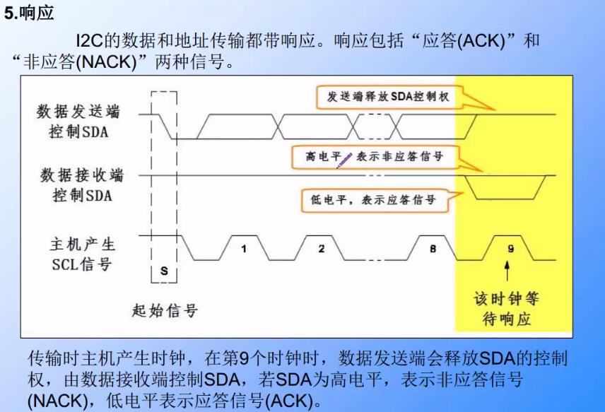
iic protocol
characteristic:
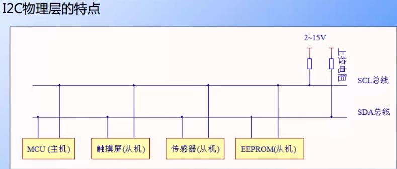
- With few pins, simple hardware implementation and strong scalability, it does not need external transceiver equipment. It is widely used in the communication between multiple integrated circuits (IC S) in the system.
- Two bus lines, one bidirectional serial data line (SDA) and one serial clock line
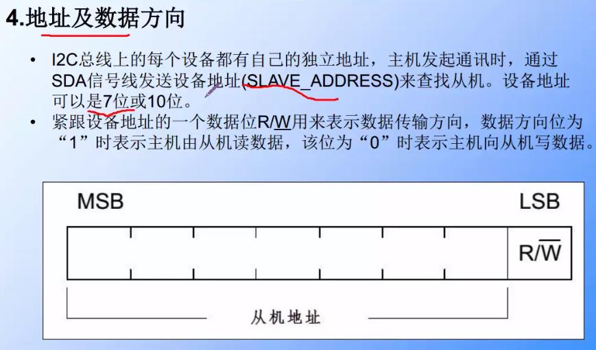
- Each device connected to the bus has an independent address (generally 7 bits, 10 bits). The host can use this address for access between different devices
- STM32 can be used as the master and slave of communication, supports the speeds of 100kbit/s and 400kbit/s, supports 7-bit and 10 bit device addresses, supports DMA data transmission, and has the function of data verification.
Programming points
(1) Configure the target pin used for communication to be in open drain mode;
(2) Enable the clock of I2C peripheral;
(3) Configure the mode, address, rate and other parameters of I2C peripherals and enable I2C peripherals;
(4) Write the function of basic I2C sending and receiving by byte;
(5) Write the function to read and write the stored content of EEPROM;
(6) Write a test program to verify the read-write data.
HAL library version
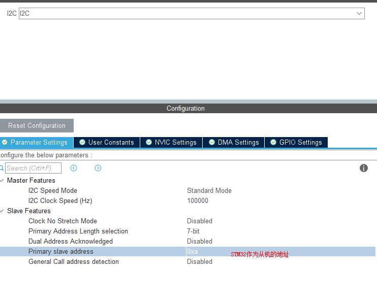
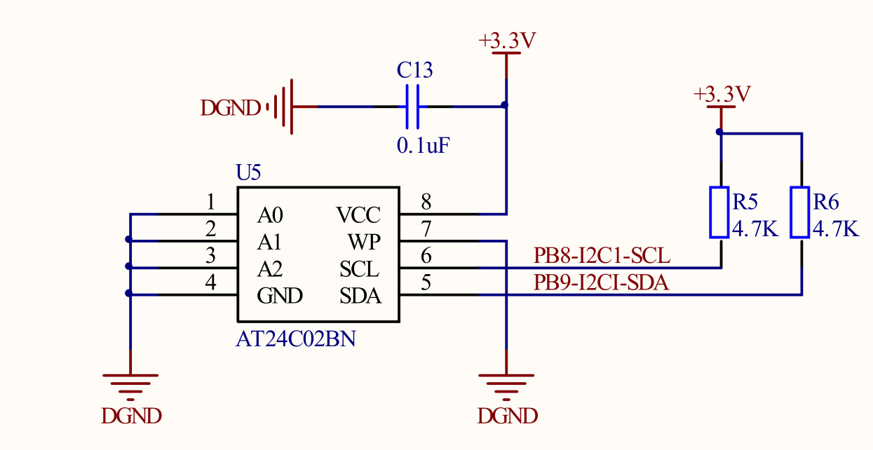
For CubeMX configuration, STM32F407VET6 can only be configured with I2C1 multiplexing pins pb8-scl and pb9-sda
IIC configuration (HAL library version)
1. I2C configuration
static void MX_I2C1_Init(void)
{
hi2c1.Instance = I2C1;
hi2c1.Init.ClockSpeed = 100000;
hi2c1.Init.DutyCycle = I2C_DUTYCYCLE_2;
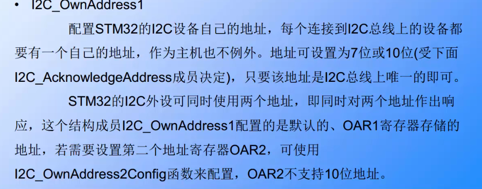
hi2c1.Init.OwnAddress1 = 0X0A;//STM32 address / / STM32 is the slave address. My CubeMX is configured with 0X0A, which becomes 20. I manually change it to 0X0A. I guess adding 0 after the seven bit address becomes 10100
hi2c1.Init.AddressingMode = I2C_ADDRESSINGMODE_7BIT;
hi2c1.Init.DualAddressMode = I2C_DUALADDRESS_DISABLE;
hi2c1.Init.OwnAddress2 = 0;
hi2c1.Init.GeneralCallMode = I2C_GENERALCALL_DISABLE;
hi2c1.Init.NoStretchMode = I2C_NOSTRETCH_DISABLE;
if (HAL_I2C_Init(&hi2c1) != HAL_OK)
{ Error_Handler();}
}
2. Main function
#include "main.h"
unsigned char WriteBuffer[256];
unsigned char ReadBuffer[256];
I2C_HandleTypeDef hi2c1;
void SystemClock_Config(void);
static void MX_GPIO_Init(void);
static void MX_I2C1_Init(void);
uint32_t I2C_EE_PageWrite(uint8_t* pBuffer, uint8_t WriteAddr, uint8_t NumByteToWrite);
uint32_t I2C_EE_ByteWrite(uint8_t* pBuffer, uint8_t WriteAddr);
void I2C_EE_BufferWrite(uint8_t* pBuffer, uint8_t WriteAddr, uint16_t NumByteToWrite);
uint32_t I2C_EE_BufferRead(uint8_t* pBuffer, uint8_t ReadAddr, uint16_t NumByteToRead);
uint8_t I2C_Test(void);
int main(void)
{
HAL_Init();
SystemClock_Config();
MX_GPIO_Init();
MX_I2C1_Init();
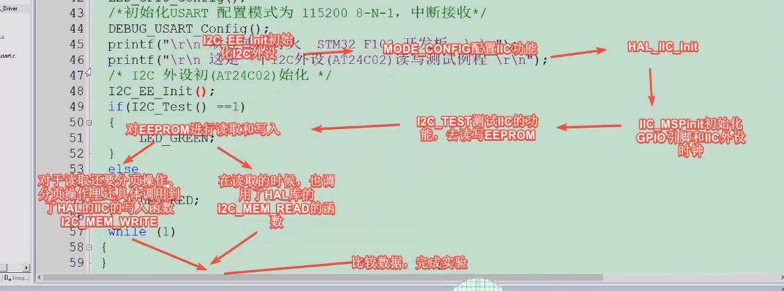
if(I2C_Test() ==1)
{
HAL_GPIO_WritePin(GPIOE, GPIO_PIN_13|GPIO_PIN_14, GPIO_PIN_SET);
}
else
{
HAL_GPIO_WritePin(GPIOE, GPIO_PIN_13, GPIO_PIN_RESET);;
}
while (1) { }
}
/**
  * @brief  I2C(AT24C02)Read write test
  * @param  nothing
  * @retval Normal return 1, abnormal return 0
  */
uint8_t I2C_Test(void)
{
	uint16_t i;

	for ( i=0; i<256; i++ ) //Fill buffer
	{
		WriteBuffer[i] =i;
		//printf("0x%02X ", I2c_Buf_Write[i]);
		//if(i%16 == 15)
		//printf("\n\r");
	}

	//Set I2C_ Buf_ The sequentially incremented data in write is written to EERPOM
	I2C_EE_BufferWrite( WriteBuffer, 0, 256);

	//EEPROM_INFO("read data");
	//Keep the EEPROM read data sequence to I2C_ Buf_ In read
	I2C_EE_BufferRead(ReadBuffer, 0, 256);
	//Set I2C_ Buf_ The data in read is printed through serial port
	for (i=0; i<256; i++)
	{
		if(ReadBuffer[i] != WriteBuffer[i])
		{
			//printf("0x%02X ", I2c_Buf_Read[i]);
			//EEPROM_ERROR("error: the data written and read by I2C EEPROM are inconsistent");
			return 0;
		}
		//printf("0x%02X ", I2c_Buf_Read[i]);
//		if(i%16 == 15)
//		printf("\n\r");

	}
	//EEPROM_INFO("I2C(AT24C02) read / write test succeeded");
	return 1;
}
/**
  * @brief   Write the data in the buffer to I2C EEPROM
  * @param
  *		@arg pBuffer:Buffer pointer
  *		@arg WriteAddr:Write address
  *     @arg NumByteToWrite:Bytes written
  * @retval  nothing
  */
void I2C_EE_BufferWrite(uint8_t* pBuffer, uint8_t WriteAddr, uint16_t NumByteToWrite)
{
  uint8_t NumOfPage = 0, NumOfSingle = 0, Addr = 0, count = 0;

  Addr = WriteAddr % 8;/* AT24C01/02 There are 8 bytes per page */
  count = 8 - Addr;
  NumOfPage =  NumByteToWrite / 8;
  NumOfSingle = NumByteToWrite % 8;

  /* If WriteAddr is I2C_PageSize aligned  */
  if(Addr == 0)
  {
    /* If NumByteToWrite < I2C_PageSize */
    if(NumOfPage == 0)
    {
      I2C_EE_PageWrite(pBuffer, WriteAddr, NumOfSingle);
    }
    /* If NumByteToWrite > I2C_PageSize */
    else
    {
      while(NumOfPage--)
      {
        I2C_EE_PageWrite(pBuffer, WriteAddr, 8);
        WriteAddr +=  8;
        pBuffer += 8;
      }

      if(NumOfSingle!=0)
      {
        I2C_EE_PageWrite(pBuffer, WriteAddr, NumOfSingle);
      }
    }
  }
  /* If WriteAddr is not I2C_PageSize aligned  */
  else
  {
    /* If NumByteToWrite < I2C_PageSize */
    if(NumOfPage== 0)
    {
      I2C_EE_PageWrite(pBuffer, WriteAddr, NumOfSingle);
    }
    /* If NumByteToWrite > I2C_PageSize */
    else
    {
      NumByteToWrite -= count;
      NumOfPage =  NumByteToWrite / 8;
      NumOfSingle = NumByteToWrite % 8;

      if(count != 0)
      {
        I2C_EE_PageWrite(pBuffer, WriteAddr, count);
        WriteAddr += count;
        pBuffer += count;
      }

      while(NumOfPage--)
      {
        I2C_EE_PageWrite(pBuffer, WriteAddr, 8);
        WriteAddr +=  8;
        pBuffer += 8;
      }
      if(NumOfSingle != 0)
      {
        I2C_EE_PageWrite(pBuffer, WriteAddr, NumOfSingle);
      }
    }
  }
}
/**
  * @brief   Write a byte to I2C EEPROM
  * @param
  *		@arg pBuffer:Buffer pointer
  *		@arg WriteAddr:Write address
  * @retval  nothing
  */
uint32_t I2C_EE_ByteWrite(uint8_t* pBuffer, uint8_t WriteAddr)
{
	HAL_StatusTypeDef status = HAL_OK;

	status = HAL_I2C_Mem_Write(&hi2c1, 0xA0, (uint16_t)WriteAddr, I2C_MEMADD_SIZE_8BIT, pBuffer, 1, 100);

	/* Check the communication status */
	if(status != HAL_OK)
	{
	/* Execute user timeout callback */
	//I2Cx_Error(Addr);
	}
	while (HAL_I2C_GetState(&hi2c1) != HAL_I2C_STATE_READY)
	{

	}

	/* Check if the EEPROM is ready for a new operation */
	while (HAL_I2C_IsDeviceReady(&hi2c1, 0xA0, 300, 300) == HAL_TIMEOUT);

	/* Wait for the end of the transfer */
	while (HAL_I2C_GetState(&hi2c1) != HAL_I2C_STATE_READY)
	{

	}
	return status;
}
/**
  * @brief   Multiple bytes can be written in one write cycle of EEPROM, but the number of bytes written at one time
  *          The size of EEPROM page cannot be exceeded. AT24C02 has 8 bytes per page
  * @param
  *		@arg pBuffer:Buffer pointer
  *		@arg WriteAddr:Write address
  *     @arg NumByteToWrite:Bytes written
  * @retval  nothing
  */
uint32_t I2C_EE_PageWrite(uint8_t* pBuffer, uint8_t WriteAddr, uint8_t NumByteToWrite)
{
	HAL_StatusTypeDef status = HAL_OK;
	/* Write EEPROM_PAGESIZE */
	status=HAL_I2C_Mem_Write(&hi2c1, 0xA0,WriteAddr, I2C_MEMADD_SIZE_8BIT, (uint8_t*)(pBuffer),NumByteToWrite, 100);

	while (HAL_I2C_GetState(&hi2c1) != HAL_I2C_STATE_READY)
	{

	}

	/* Check if the EEPROM is ready for a new operation */
	while (HAL_I2C_IsDeviceReady(&hi2c1, 0xA0, 300, 300) == HAL_TIMEOUT);

	/* Wait for the end of the transfer */
	while (HAL_I2C_GetState(&hi2c1) != HAL_I2C_STATE_READY)
	{

	}
	return status;
}

/**
  * @brief   Read a piece of data from EEPROM
  * @param
  *		@arg pBuffer:Buffer pointer to store data read from EEPROM
  *		@arg WriteAddr:Address of EEPROM receiving data
  *     @arg NumByteToWrite:Number of bytes to read from EEPROM
  * @retval  nothing
  */
uint32_t I2C_EE_BufferRead(uint8_t* pBuffer, uint8_t ReadAddr, uint16_t NumByteToRead)
{
	HAL_StatusTypeDef status = HAL_OK;
	//Handle, device address, device internal register address, storage unit size, data storage buffer, how many data to read, timeout time
	status=HAL_I2C_Mem_Read(&hi2c1,0xA0,ReadAddr, I2C_MEMADD_SIZE_8BIT, (uint8_t *)pBuffer, NumByteToRead,1000);

	return status;
}
Write data analysis from EEPROM
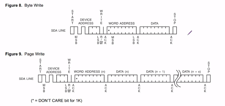
Write up to one page at a time, and eeprom has 8 bytes per page
So page write function I2C_EE_PageWrite(pBuffer, WriteAddr, 8); —> HAL_ I2C_ Mem_ Write(&hi2c1, 0xA0,WriteAddr, I2C_MEMADD_SIZE_8BIT, (uint8_t*)(pBuffer),8, 100);
Write a byte to I2C EEPROM, I2C_EE_ByteWrite(uint8_t* pBuffer, uint8_t WriteAddr)–>HAL_ I2C_ Mem_ Write(&hi2c1, 0xA0, (uint16_t)WriteAddr, I2C_MEMADD_SIZE_8BIT, pBuffer, 1, 100);
Read data analysis from EEPROM
I2C_ EE_ BufferRead(ReadBuffer, 0, 256);------> HAL_ I2C_ Mem_ Read() as shown in the figure below, eeprom can be read at one time
`//Handle, device address, device internal register address, storage unit size, data storage buffer, how many data to read, timeout time
HAL_I2C_Mem_Read(&hi2c1,0xA0,ReadAddr, I2C_MEMADD_SIZE_8BIT, (uint8_t *)pBuffer, NumByteToRead,1000);`
IIC configuration (firmware library version)
static void I2C_GPIO_Config(void)
{
  GPIO_InitTypeDef  GPIO_InitStructure;
	I2C_InitTypeDef   I2CS;
	RCC_APB1PeriphClockCmd(RCC_APB1Periph_I2C1,ENABLE);//IIC clock
	RCC_APB2PeriphClockCmd(RCC_APB2Periph_GPIOB,ENABLE);//GPIO clock
	 /* I2C_SCL,I2C_SDA*/
  GPIO_InitStructure.GPIO_Pin =  GPIO_Pin_6;
  GPIO_InitStructure.GPIO_Speed = GPIO_Speed_50MHz;
  GPIO_InitStructure.GPIO_Mode = GPIO_Mode_AF_OD;	       // Multiplexed open drain output
  GPIO_Init( GPIOB , &GPIO_InitStructure);

  GPIO_InitStructure.GPIO_Pin = GPIO_Pin_7;
  GPIO_InitStructure.GPIO_Speed = GPIO_Speed_50MHz;
  GPIO_InitStructure.GPIO_Mode = GPIO_Mode_AF_OD;	       // Multiplexed open drain output
  GPIO_Init(GPIOB, &GPIO_InitStructure);
	/* I2C to configure */
	I2CS.I2C_Mode=I2C_Mode_I2C;
	/* The high-level data is stable, and the low-level data changes the duty cycle of SCL clock line */
	I2CS.I2C_DutyCycle=I2C_DutyCycle_2;
	I2CS.I2C_Ack=I2C_Ack_Enable;
	I2CS.I2C_AcknowledgedAddress=I2C_AcknowledgedAddress_7bit;//Select the addressing mode of the 7-bit address
	I2CS.I2C_ClockSpeed=400000;/* Communication rate */
	I2CS.I2C_OwnAddress1= 0X0A  ;//STM32 address
  I2C_Init(I2C1, &I2CS);/* I2C initialization */
	/* Enable I2C */
  I2C_Cmd(I2C1, ENABLE);
}
IIC physical layer characteristics
- The pull-up resistance is generally 4.7K Ω
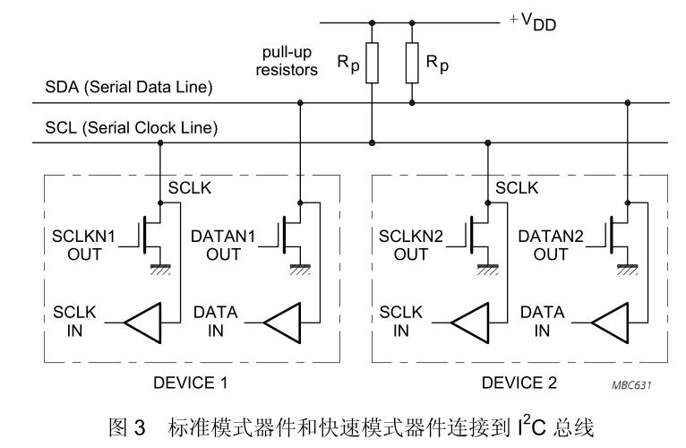
- The bus is connected to the power supply through the pull-up resistor. When the I2C device is idle, it will output the high resistance state. When all devices are idle and output the high resistance state, the pull-up resistor will pull the bus to the high level, line and characteristics
- The device output stage connected to the bus must be open drain or open collector to perform the function of line and, so STM32 pin should be configured as open drain output
- The number of interfaces connected to the bus is only determined by the limit that the bus capacitance is 400pF
- The data transmission rate on I 2C bus can reach 100kbit/s in standard mode, 400kbit/s in fast mode and 3.4Mbit/s in high-speed mode
IIC agreement features
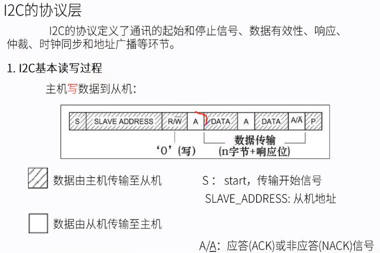
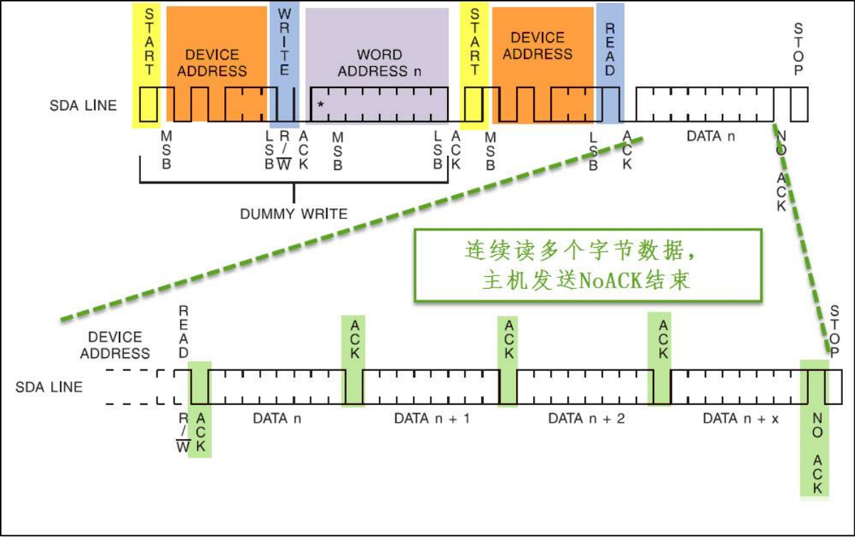
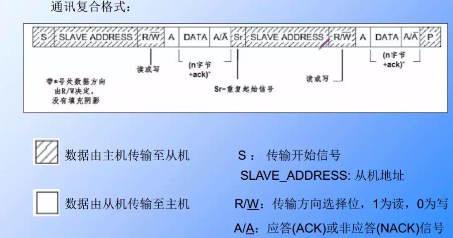
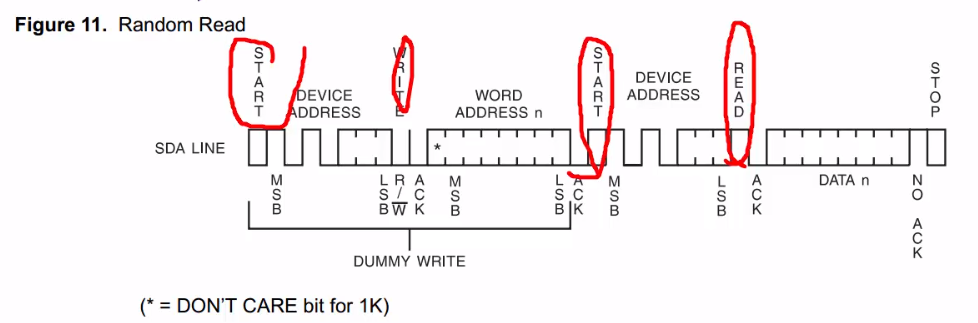
Communication composite format:
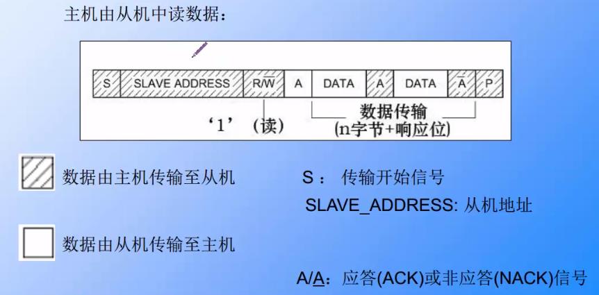
1. Start signal - write direction (device address) - write data (memory internal address) - start signal - device address (same as before) - read and write operation
There will be two start signals
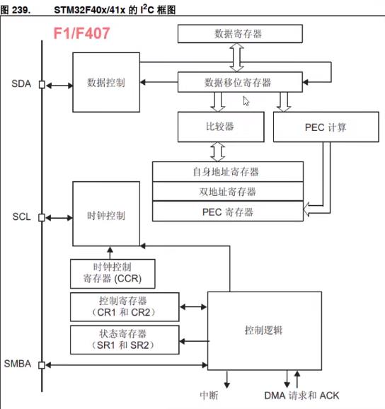
I2C frame
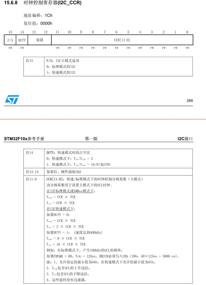
Clock control register (CCR)
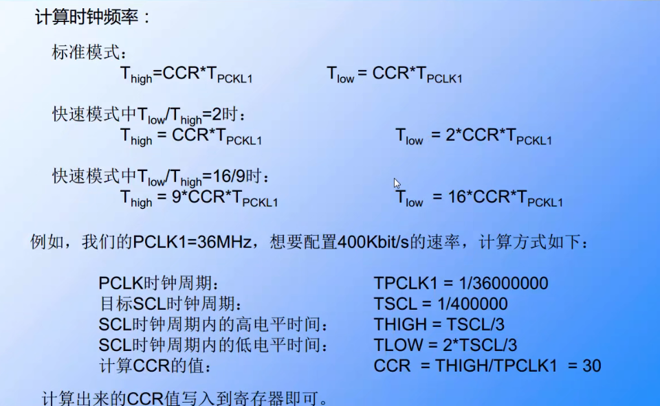
The clock signal of SCL line is controlled by IIC interface according to clock control register (CCR), and the main control parameter is clock frequency
- The "standard / fast" mode can be selected, corresponding to the communication rate of 100/400Kbit/s respectively
- In the fast mode, you can select the duty cycle of SCL clock, T low /T high = 2 or T low /T high = 16/9
- The 12 bit configuration factor CCR in the CCR register works with the input clock source of IIC peripheral to generate SCL clock. The IIC peripheral input clock source of STM32 is PCLK1.
Data control logic
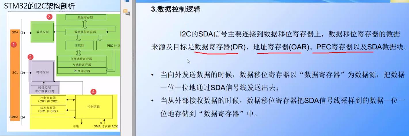
Schematic diagram of STM32F407VET6 and EEROM
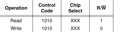
write
DEVICE ADDRESS is the DEVICE ADDRESS
WORD ADDRESS is the register address
byte write needs to ask after each write, and then send the start signal and device address, because it is slow to write data
page write can be written continuously, and 1K/2K EEROM can write up to 8-byte s at a time
read
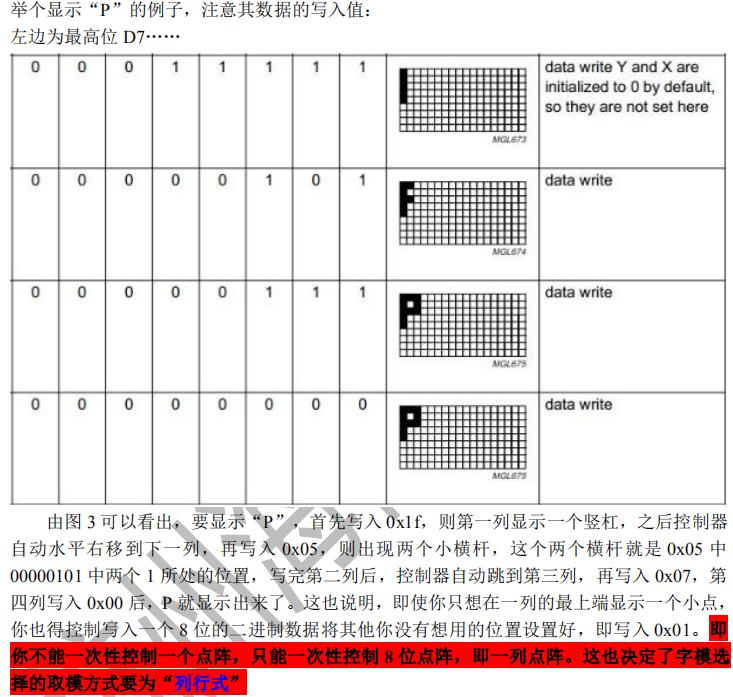
stm32 communicates with 128*64 OLED LCD IIC
128*64 OLED, 128 horizontal points and 64 vertical points.
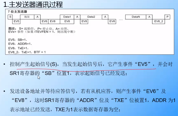
I2C_CheckEvent()
/* Test on EV5 and clear it */
while(!I2C_CheckEvent(I2C1, I2C_EVENT_MASTER_MODE_SELECT));
/* Test on EV6 and clear it */
while(!I2C_CheckEvent(I2C1, I2C_EVENT_MASTER_TRANSMITTER_MODE_SELECTED));