Change from: http://dpinglee.blog.163.com/blog/static/14409775320112239374615/
1.I2C protocol
Two bidirectional serial lines, one data line SDA and one clock line SCL.SDA transmission data is a large-end transmission, each transmission of 8 bits, that is, a byte.
Multi-mastering is supported, and there can only be one master at any point in time.
Each device on the bus has its own addr, a total of 7 bit s, and the broadcast address is all 0.
There may be multiple chips of the same kind in the system, so addr can be divided into fixed and programmable parts, depending on the chip, depending on the data sheet.
1.1 I2C bit transmission
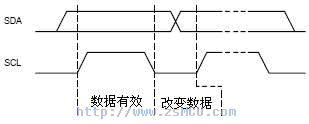
Data transmission: SCL is high level, if SDA line remains stable, then SDA is transmitting data bit;
If SDA jumps, it is used to indicate the beginning or end of a session (later)
Data change: When SCL is low, SDA line can change bit of transmission.

Start signal: SCL is high level, SDA jumps from high level to low level, and begins to transmit data.
End signal: SCL is high level, SDA jumps from low level to high level, and ends data transmission.

1.3 I2C response signal
In the 9th clock, if ACK is sent from IC, SDA will be pulled down.
Without ACK, SDA will be set high, which will cause Master to have RESTART or STOP processes, as follows:

The standard process for writing registers is:
1. Master initiates START
2. Master sends I2C addr (7bit) and w operation 0 (1bit), waiting for ACK
3. Slave sends ACK
4. Master sends reg addr (8bit) and waits for ACK
5. Slave sends ACK
6. Master sends data (8bit), that is, data to be written to registers, waiting for ACK
7. Slave sends ACK
8. Steps 6 and 7 can be repeated many times, i.e. writing multiple registers sequentially
9. Master launched STOP
Write a register


The standard process of reading registers is as follows:
Master sends I2C addr (7bit) and w operation 1 (1bit), waiting for ACK
2. Slave sends ACK
3. Master sends reg addr (8bit) and waits for ACK
4. Slave sends ACK
5. Master launched START
6. Master sends I2C addr (7bit) and r operation 1 (1bit), waiting for ACK
7. Slave sends ACK
8. Slave sends data (8bit), which is the value in the register.
9. Master sends ACK
10. Steps 8 and 9 can be repeated many times, i.e. sequential reading of multiple registers
Read a register


There are six registers controlling I2C in CCSR of Mpc8560.

2.1 I2CADR address register


Used to set I2C bus frequency
2.3 I2CCR Control Register

MEN: Module Enable. When set to 1, I2C module is enabled
MIEN: Module Interrupt Enable. When set to 1, I2C interrupts enabling.
MSTA: Master/slave mode. 1 Master mode,0 Slave mode.
When 1->0, CPU initiates STOP signal
When 0->1, CPU initiates START signal
MTX: Transmit/receive mode select.0 Receive mode,1 Transmit mode
TXAK: Transfer acknowledge. Set 1, CPU sends ACK at 9th clock to lower SDA
RSTA: Repeat START. When set 1, the CPU sends REPEAT START
BCST: Set 1, CPU receives broadcast information (slave addr of information is 7 zeros)
2.4 I2CSR status register

1 Byte transfer is completed
MAAS: When the CPU acts as Slave, if I2CDR matches Slaveaddr in the session, the bit is set to 1
MBB: 0 I2C bus idle
1 I2C bus busy
MAL: If set to 1, the arbitration will fail.
BCSTM: If set to 1, it means receiving broadcast information.
SRW: When MAAS is set, SRW indicates the value of the R/W command bit of the calling address, which is sent from the master.
0 Slave receive, master writing to slave
1 Slave transmit, master reading from slave
MIF: Module interrupt. The MIF bit is set when an interrupt is pending, causing a processor interrupt request(provided I2CCR[MIEN] is set)
RXAK: If you set 1, you receive ACK.
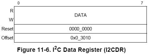
2.5 I2CDR Data Register

This register stores the data that the CPU will transmit.
3. Implementation of I2C in PPC-Linux
In the kernel code, the functions accessing registers through the I2C bus are in the file drivers/i2c/buses/i2c-mpc.c.
The most important function is mpc_xfer.
static int mpc_xfer(struct i2c_adapter *adap, struct i2c_msg *msgs, int num)
{
    struct i2c_msg *pmsg;
    int i;
    int ret = 0;
    unsigned long orig_jiffies = jiffies;
    struct mpc_i2c *i2c = i2c_get_adapdata(adap);

    mpc_i2c_start(i2c);    // Set up I2CCR[MEN] to enable I2C module

    /* Allow bus up to 1s to become not busy */
    //Read I2CSR[MBB] all the time, waiting for the I2C bus to be idle
    while (readb(i2c->base + MPC_I2C_SR) & CSR_MBB) {
        if (signal_pending(current)) {
            pr_debug("I2C: Interrupted\n");
            writeccr(i2c, 0);
            return -EINTR;
        }
        if (time_after(jiffies, orig_jiffies + HZ)) {
            pr_debug("I2C: timeout\n");
            if (readb(i2c->base + MPC_I2C_SR) ==
                (CSR_MCF | CSR_MBB | CSR_RXAK))
                mpc_i2c_fixup(i2c);
            return -EIO;
        }
        schedule();
    }

    for (i = 0; ret >= 0 && i < num; i++) {
        pmsg = &msgs[i];
        pr_debug("Doing %s %d bytes to 0x%02x - %d of %d messages\n",
             pmsg->flags & I2C_M_RD ? "read" : "write",
             pmsg->len, pmsg->addr, i + 1, num);
        //Read or write based on flag in the message
        if (pmsg->flags & I2C_M_RD)
            ret = mpc_read(i2c, pmsg->addr, pmsg->buf, pmsg->len, i);
        else
            ret = mpc_write(i2c, pmsg->addr, pmsg->buf, pmsg->len, i);
    }
    mpc_i2c_stop(i2c);    //Guarantee that I2CCSR[MSTA] is 0 to trigger STOP
    return (ret < 0) ? ret : num;
}


static int mpc_write(struct mpc_i2c *i2c, int target,
             const u8 * data, int length, int restart)
{
    int i;
    unsigned timeout = i2c->adap.timeout;
    u32 flags = restart ? CCR_RSTA : 0;

    /* Start with MEN */    //Just in case, make sure the I2C module is enabled
    if (!restart)
        writeccr(i2c, CCR_MEN);
    /* Start as master */       //Write I2CCR[CCR_MSTA], trigger CPU to initiate START signal
    writeccr(i2c, CCR_MIEN | CCR_MEN | CCR_MSTA | CCR_MTX | flags);
    /* Write target byte */     //The CPU sends a byte, slave I2C addr and 0 (write bit)
    writeb((target << 1), i2c->base + MPC_I2C_DR);

    if (i2c_wait(i2c, timeout, 1) < 0)    //Waiting for slave to issue ACK
        return -1;

    for (i = 0; i < length; i++) {
        /* Write data byte */
        writeb(data[i], i2c->base + MPC_I2C_DR); //CPU then sends data, including reg addr and data

        if (i2c_wait(i2c, timeout, 1) < 0)       //Waiting for slave to issue ACK
            return -1;
    }

    return 0;
}


static int i2c_wait(struct mpc_i2c *i2c, unsigned timeout, int writing)
{
    unsigned long orig_jiffies = jiffies;
    u32 x;
    int result = 0;

    if (i2c->irq == 0)
    {    //Read I2CSR iteratively until I2CSR[MIF] sets 1
        while (!(readb(i2c->base + MPC_I2C_SR) & CSR_MIF)) {
            schedule();
            if (time_after(jiffies, orig_jiffies + timeout)) {
                pr_debug("I2C: timeout\n");
                writeccr(i2c, 0);
                result = -EIO;
                break;
            }
        }
        x = readb(i2c->base + MPC_I2C_SR);
        writeb(0, i2c->base + MPC_I2C_SR);
    } else {
        /* Interrupt mode */
        result = wait_event_interruptible_timeout(i2c->queue,
            (i2c->interrupt & CSR_MIF), timeout * HZ);

        if (unlikely(result < 0)) {
            pr_debug("I2C: wait interrupted\n");
            writeccr(i2c, 0);
        } else if (unlikely(!(i2c->interrupt & CSR_MIF))) {
            pr_debug("I2C: wait timeout\n");
            writeccr(i2c, 0);
            result = -ETIMEDOUT;
        }

        x = i2c->interrupt;
        i2c->interrupt = 0;
    }

    if (result < 0)
        return result;

    if (!(x & CSR_MCF)) {
        pr_debug("I2C: unfinished\n");
        return -EIO;
    }

    if (x & CSR_MAL) {    //Arbitration failure
        pr_debug("I2C: MAL\n");
        return -EIO;
    }

    if (writing && (x & CSR_RXAK)) {//No ACK was received after writing.
        pr_debug("I2C: No RXAK\n");
        /* generate stop */
        writeccr(i2c, CCR_MEN);
        return -EIO;
    }
    return 0;
}

static int mpc_read(struct mpc_i2c *i2c, int target,
            u8 * data, int length, int restart)
{
    unsigned timeout = i2c->adap.timeout;
    int i;
    u32 flags = restart ? CCR_RSTA : 0;

    /* Start with MEN */    //Ensure the I2C module is enabled just in case
    if (!restart)
        writeccr(i2c, CCR_MEN);
    /* Switch to read - restart */
    //Notice here, set CCR_MSTA to 1 again, and then trigger START.
    writeccr(i2c, CCR_MIEN | CCR_MEN | CCR_MSTA | CCR_MTX | flags);


    /* Write target address byte - this time with the read flag set */
    //CPU sends slave I2C addr and read operation 1
    writeb((target << 1) | 1, i2c->base + MPC_I2C_DR);

     //Waiting for Slave to issue ACK
    if (i2c_wait(i2c, timeout, 1) < 0)
        return -1;

    if (length) {
        if (length == 1)
            writeccr(i2c, CCR_MIEN | CCR_MEN | CCR_MSTA | CCR_TXAK);
        else //Why not leave TXAK
            writeccr(i2c, CCR_MIEN | CCR_MEN | CCR_MSTA);
        /* Dummy read */
        readb(i2c->base + MPC_I2C_DR);
    }

    for (i = 0; i < length; i++) {
        if (i2c_wait(i2c, timeout, 0) < 0)
            return -1;

        /* Generate txack on next to last byte */
        //Note that TXAK is set to 1, which means that the CPU sends ACK every time it receives 1 byte data.
        if (i == length - 2)
            writeccr(i2c, CCR_MIEN | CCR_MEN | CCR_MSTA | CCR_TXAK);

        /* Generate stop on last byte */
        //Note here that the CCR_MSTA [1->0] CPU triggers STOP
        if (i == length - 1)
            writeccr(i2c, CCR_MIEN | CCR_MEN | CCR_TXAK);

        data[i] = readb(i2c->base + MPC_I2C_DR);
    }

    return length;
}