The previous two articles (Register Configuration Lighting LED and Device Tree Lighting LED) are essentially register configurations to control the lighting of LEDs.
- The direct operation of registers is to write the register information related to the LED directly into the driver code of the LED, which is also a more general control method. However, when the registers of the chip change, the underlying drivers need to be rewritten.
- The way to use the device tree is to write the register information related to the LED to the device tree file. When the device information is modified, the device information can also be obtained through the interface function of the device tree, which improves the reuse ability of the driver code.
- The Pinctrl and GPIO subsystems described in this article do not need to operate registers directly anymore, because these two subsystems have already implemented register operation for us, we only need to operate API functions provided by these two subsystems.
1 Pinctrl Subsystem
Pintrl subsystem, as its name implies, is a system that manages pins, such as brightening the LEDs, that is, to control the low and high levels of the corresponding pins of the LEDs, the pins corresponding to the LEDs must first be multiplexed into GPIO functions through the Pintrl subsystem (is this similar to the functions of MUX registers used in the previous register configuration).
1.1 iomuxc node in device tree
How do I use the Pintrl subsystem? In fact, it also depends on the device tree. First, let's look at the iomuxc node in the device tree, which is the corresponding node of the IOMUXC peripheral and responsible for the reuse of IO functions.
Open the device tree file for your development board (my name is imx6ull-myboard.dts), then find the iomuxc node, and take a look at its basic structure:
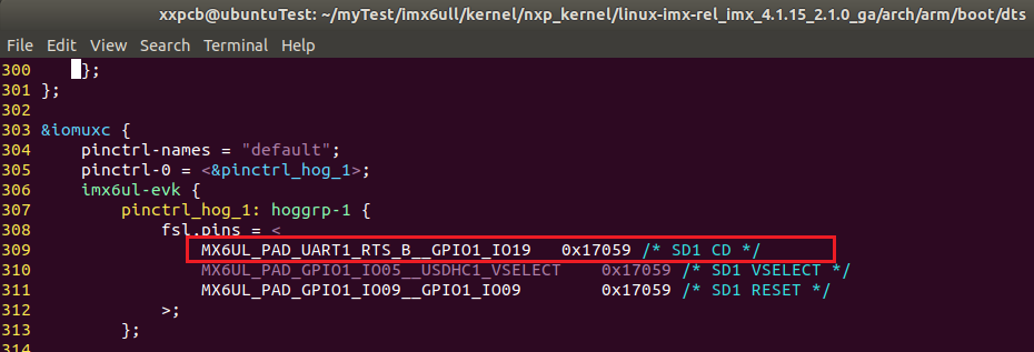
&iomuxc {
	pinctrl-names = "default";
	pinctrl-0 = <&pinctrl_hog_1>;
	imx6ul-evk {
		pinctrl_hog_1: hoggrp-1 {
			fsl,pins = <
				MX6UL_PAD_UART1_RTS_B__GPIO1_IO19	    0x17059 /* SD1 CD */
				MX6UL_PAD_GPIO1_IO05__USDHC1_VSELECT	0x17059 /* SD1 VSELECT */
				MX6UL_PAD_GPIO1_IO09__GPIO1_IO09        0x17059 /* SD1 RESET */
			>;
		};

		pinctrl_csi1: csi1grp {
			fsl,pins = <
				MX6UL_PAD_CSI_MCLK__CSI_MCLK		0x1b088
				MX6UL_PAD_CSI_PIXCLK__CSI_PIXCLK	0x1b088
				MX6UL_PAD_CSI_VSYNC__CSI_VSYNC		0x1b088
				MX6UL_PAD_CSI_HSYNC__CSI_HSYNC		0x1b088
				MX6UL_PAD_CSI_DATA00__CSI_DATA02	0x1b088
				MX6UL_PAD_CSI_DATA01__CSI_DATA03	0x1b088
				MX6UL_PAD_CSI_DATA02__CSI_DATA04	0x1b088
				MX6UL_PAD_CSI_DATA03__CSI_DATA05	0x1b088
				MX6UL_PAD_CSI_DATA04__CSI_DATA06	0x1b088
				MX6UL_PAD_CSI_DATA05__CSI_DATA07	0x1b088
				MX6UL_PAD_CSI_DATA06__CSI_DATA08	0x1b088
				MX6UL_PAD_CSI_DATA07__CSI_DATA09	0x1b088
			>;
		};
        //Omit...
Here's pinctrl_hog_1 The plug-and-drop subnode is analyzed as an example. It is a pin collection related to hot-plug, such as the ID pin of USB OTG, pinctrl_ The csi1 subnode is the PIN used by the CSI peripheral. In this article, you need to control the lighting of the LED. You need to create a new corresponding node, and then put all Pin configuration information of this custom peripheral into this subnode.
1.2 Interpretation of Macro Definition
For pinctrl_hog_1 This byte point, notice that:
MX6UL_PAD_UART1_RTS_B__GPIO1_IO19 0x17059 /* SD1 CD */
This is the Pin pin configuration, which includes two aspects: one is to set up the Pin's reuse function, the other is to set the Pin's electrical characteristics.
Previous MX6UL_ PAD_ UART1_ RTS_ B_u GPIO1_ IO19 This macro definition is defined in arch/arm/boot/dts/imx6ul-pinfunc.h (note that imx6ull.dtsi references imx6ull-pinfunc.h, and imx6ull-pinfunc.h references imx6ul-pinfunc.h)
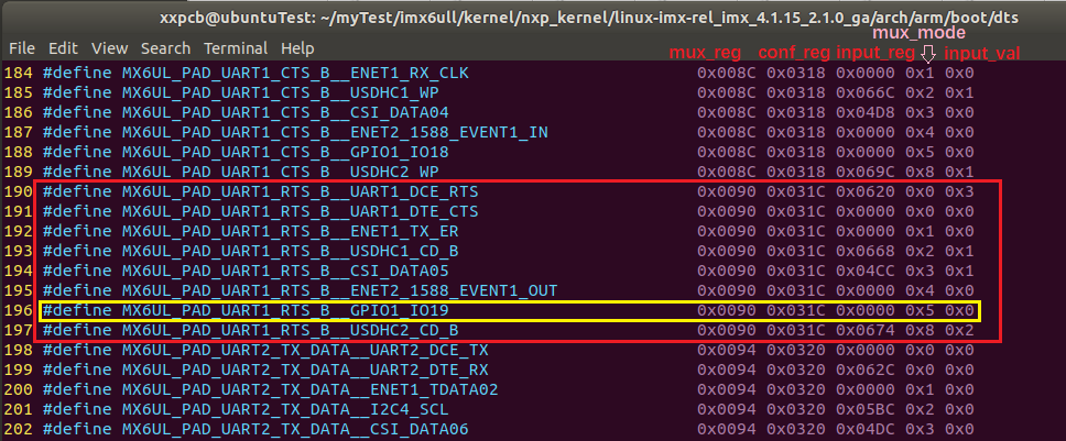
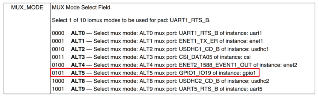
There are eight in total here in MX6UL_ PAD_ UART1_ RTS_ The macro definitions at the beginning of B represent eight different functions of this IO.
In addition, the value defined by this macro is divided into five segments, each of which has a specific meaning:
-
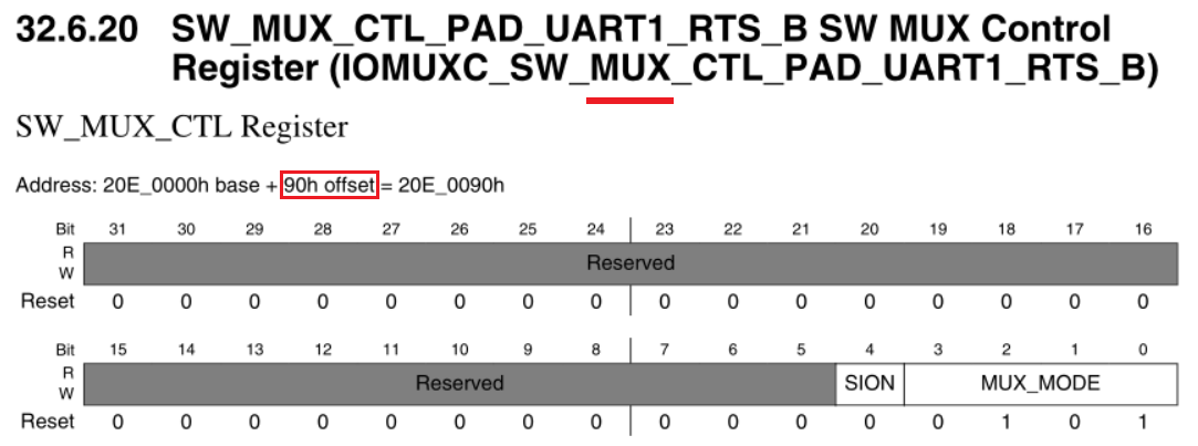
0x0090 mux_reg register offset address
-
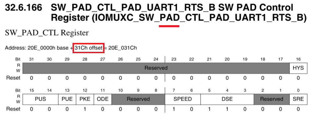
**0x031C **conf_reg register offset address
-
0x0000 input_reg register offset address (invalid here)
-
0x5 mux_ Value of reg register
-
0x0 input_reg register value (invalid here)
2 GPIO Subsystem
The GPIO subsystem, as its name implies, is a system that manages GPIO functionality by initializing the configuration of GPIO (which is a bit like the PAD registers used in previous register configurations) and providing external API interfaces. After using the GPIO subsystem, you do not need to operate the registers by yourself. You can control the GPIO by calling the API function provided by the GPIO subsystem.
2.1 gpio information in device tree
Still take a hot-plug node as an example:
UART1_RTS_B multiplexed as GPIO1_IO19, read its high and low level to determine if the SD card is inserted.
How does the SD card driver know the GPIO1_of the CD pin connection IO19? Or the device tree tells the driver to add an attribute under the SD card node in the device tree to describe the SD card's CD pin:
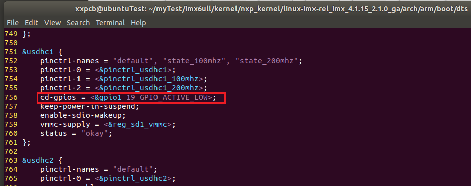
The cd-gpios describes which IO the SD card's CD pin uses, with three attribute values:
- &gpio1 indicates that the IO used by the CD pin belongs to the GPIO1 group
- 19 represents the 19th IO of the GPIO1 group
- GPIO_ACTIVE_LOW indicates low level is valid
Based on the above information, the SD card driver can use GPIO1_IO19 to detect SD card CD signal
2.2 gpio subsystem API function
2.2.1 gpio_request/free
- gpio_request
Used to request a GPIO pin
/**
 * gpio: The GPIO label to apply for (the label returned when the specified GPIO attribute information is obtained from the device tree using the of_get_named_gpio function)
 * label: Give gpio a name
 * return: 0-Application Success Other Values - Application Failure
 */
int gpio_request(unsigned gpio,  const char *label)
- gpio_free
Used to release a GPIO pin
/**
 * gpio: gpio label to release
 * return
 */
void gpio_free(unsigned gpio)
2.2.2 gpio_direction_input/output
- gpio_direction_input
Used to set a GPIO as input
/**
 * gpio: GPIO label to be set as input
 * return: 0-Setting Successful Negative - Setting Failed
 */
int gpio_direction_input(unsigned gpio)
- gpio_direction_output
This function sets a GPIO as output and sets the default output value
/**
 * gpio: GPIO label to be set as output
 * value: GPIO Default Output Value
 * return 0-Setting Successful Negative - Setting Failed
 */
int gpio_direction_output(unsigned gpio, int value)
2.2.3 gpio_get_value/set_value
- gpio_get_value
This function is used to get the value of a GPIO (0 or 1)
#define gpio_get_value  __gpio_get_value
/**
 * gpio: gpio label to get
 * return: Non-Negative - Negative gpio value obtained - Failed to get
 */
int __gpio_get_value(unsigned gpio)
- gpio_set_value
Value used to set a GPIO
#define gpio_set_value  __gpio_set_value
/**
 * gpio: gpio label to set
 * value: Value to set
 * return
 */
void __gpio_set_value(unsigned gpio, int value)
2.3 OF function related to gpio
2.3.1 of_gpio_named_count
Used to get several GPIO information defined in a property of the device tree
/**
 * np: Device Node
 * propname: gpio attributes to be counted
 * return: Positive - Number of gpio counted negative - Failed
 */
int of_gpio_named_count(struct device_node *np, const char  *propname)
2.3.2 of_gpio_count
Count the number of gpios for the property "gpios"
/**
 * np: Device Node
 * return: Positive - Number of gpio counted negative - Failed
 */
int of_gpio_count(struct device_node *np)
2.3.3 of_get_named_gpio
Get GPIO Number
/**
 * np: Device Node
 * propname: Property name containing gpio information to be obtained
 * index: gpio Index (an attribute may contain more than one gpio)
 * return: Positive - Obtained negative gpio number - Failed
 */
int of_get_named_gpio(struct device_node *np,
                              const char *propname,
                                     int index)
3 Pinctr Edition LED Driver
The basic situation of Pinctrl and GPIO subsystems is described above, and they can be used to control the illumination and extinction of LED.
3.1 Modify device tree file
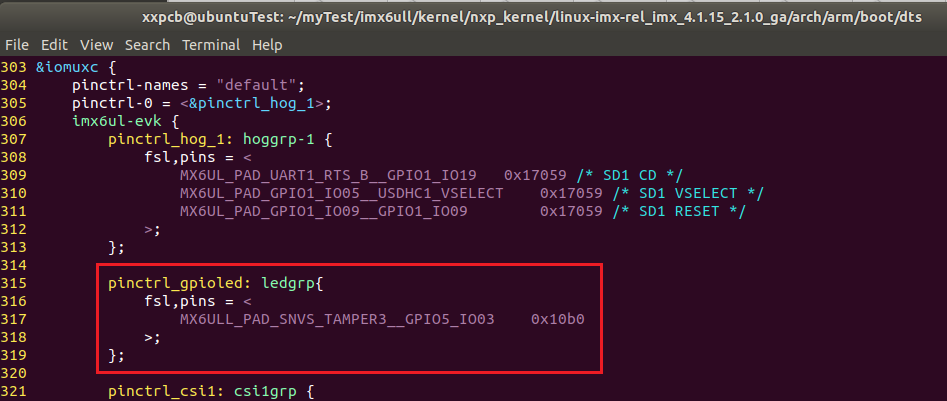
Modify imx6ull-myboard.dts to create a pinctrl_under the imx6ull-evk byte point of the iomuxc node Child node of led, node content is as follows:
pinctrl_gpioled: ledgrp{
    fsl,pins = <
        MX6ULL_PAD_SNVS_TAMPER3__GPIO5_IO03    0x10b0
        >;
};
-
MX6ULL_ PAD_ SNVS_ TAMPER3_u GPIO5_ io03 means that the io is multiplexed as GPIO
-
0x10b0 represents the configuration value of the PAD register, which means the following, as described in the previous article( Drive Development 4 - Light up LED (Register Edition) ) Yes.
/*Register SW_PAD_SNVS_TAMPER3 Set IO Properties
     *bit 16:0 HYS Close
     *bit [15:14]: 00 Default Dropdown
     *bit [13]: 0 kepper function
     *bit [12]: 1 pull/keeper Enabling
     *bit [11]: 0 Turn off open-circuit output
     *bit [7:6]: 10 Speed 100Mhz
     *bit [5:3]: 110 R0/6 Driving power
     *bit [0]: 0 Low conversion rate
     */
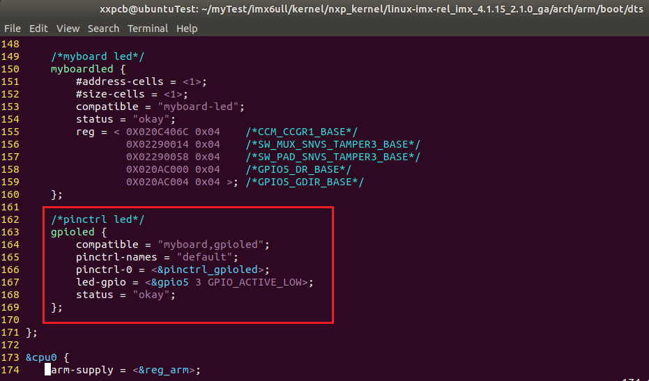
Create an LED node named gpioled under the root node, as follows:
/*pinctrl led*/
gpioled {
    compatible = "myboard,gpioled";
    pinctrl-names = "default";
    pinctrl-0 = <&pinctrl_gpioled>;
    led-gpios = <&gpio5 3 GPIO_ACTIVE_LOW>;
    status = "okay";
};
- pinctrl-0 sets the pinctrl node corresponding to the PIN used by the LED
- led-gpio specifies the GPIO used by the LED, here is IO03 of GPIO5, low level valid
3.2 Check pin usage conflict
Since the device tree file used by my development board (imx6ull-myboard.dts) was modified from the device tree file (imx6ull-14x14-evk.dts) officially provided by NXP, it is possible that some pins are not configured as your own development board and you need to check for any usage conflicts.
This MX6ULL_added this time PAD_ SNVS_ TAMPER3_u GPIO5_ IO03 does not conflict with other pins in the file and therefore does not need to be modified.
3.3 Modify LED driver files
Modified on the driver file of the last device tree edition, the main modifications are as follows.
A header file needs to be added:
#include <linux/of_gpio.h>
Change device structure to gpio_led:
/* gpioled Device Architecture */
struct gpioled_dev{
    dev_t         devid;    /* Device Number   */
    struct cdev   cdev;     /* cdev     */
    struct class  *class;   /* class       */
    struct device *device;  /* equipment     */
    int           major;    /* Main device number */
    int           minor;    /* Secondary device number */
    struct device_node *nd; /* Device Node */
    int           led_gpio; /* led GPIO number used*/
};

struct gpioled_dev gpioled;    /* led equipment */
The hardware initialization part is the main modification. This time, there is no need to read register operation from the device tree or do I/O memory mapping by itself. Instead, the GPIO of the LED is configured using the API function of the GPIO subsystem:
static int gpioled_hardware_init(void)
{
    int ret;

    /* Get the attribute data in the device tree */
    /* 1,Get device node: gpioled */
    gpioled.nd = of_find_node_by_path("/gpioled");
    if(gpioled.nd == NULL)
    {
        printk("gpioled node not find!\r\n");
        return -EINVAL;
    }
    else
    {
        printk("gpioled node find!\r\n");
    }

    /* 2,Get the gpio property, get the LED number */
    gpioled.led_gpio = of_get_named_gpio(gpioled.nd, "led-gpio", 0);
    if(gpioled.led_gpio < 0)
    {
        printk("can't get led-gpio!\r\n");
        return -EINVAL;
    }
    else
    {
        printk("led-gpio num = %d\r\n", gpioled.led_gpio);
    }

    /* 3,Set GPIO as output and turn off LED by default */
    ret = gpio_direction_output(gpioled.led_gpio, 1);
    if(ret < 0)
    {
        printk("can't set led-gpio!\r\n");
    }

    return 0;
}
When switching on and off the LED, you no longer need to directly operate the registers, but also use API functions to operate:
static ssize_t gpioled_write(struct file *filp, const char __user *buf, size_t cnt, loff_t *offt)
{
	//Omit...

    if(ledstat == LEDON)
    {
        gpio_set_value(dev->led_gpio, 0);         /* Turn on the LED light */
        printk("led on!\n");
    }
    else if(ledstat == LEDOFF)
    {
        gpio_set_value(dev->led_gpio, 1);        /* Turn off LED lights */
        printk("led off!\n");
    }

    return 0;
}
4 Experimental Test
4.1 Compiler
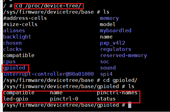
- Compile the device tree file (.dtb), as in the previous experiment where the device tree lights up the LED, first copy the device tree file to the nfs file system location, then boot the development board from the network, and check in the serial port if there are any gpioled nodes added to the device tree:
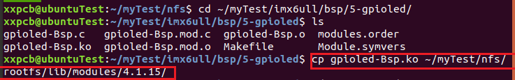
- Compile the LED driver file (.ko) and copy it to the rootfs/lib/modules/4.1.15 directory:
- The LED application does not need to be changed, just use the same program that was used when the previous register version was used to light up the LED experiment.
4.2 Test
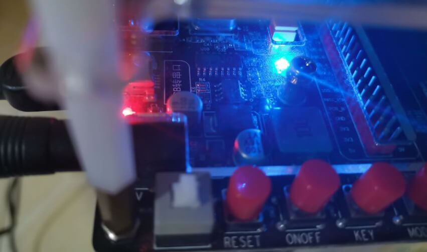
As before, the test was done by loading the driver file and then calling the application to control the lighting of the LED:
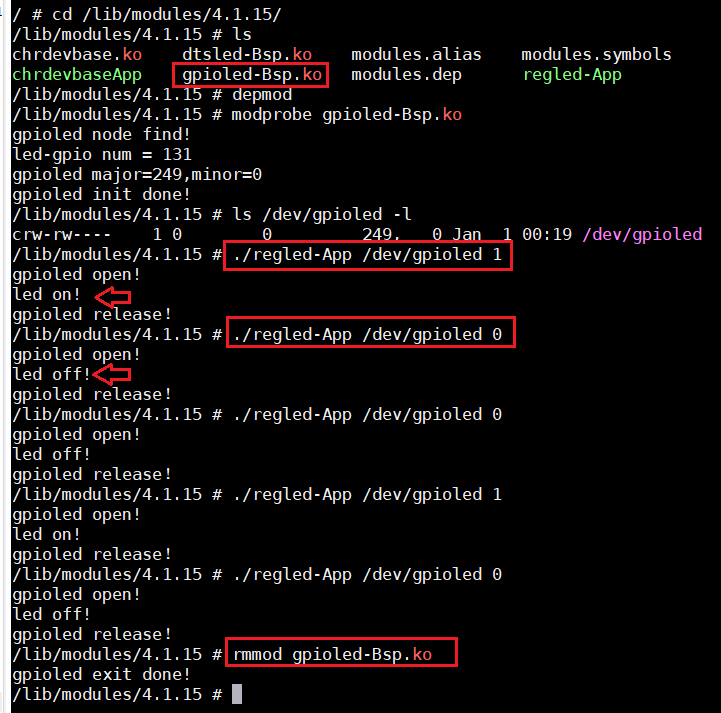
The effect is the same as previous register version lighting LED and device tree version lighting LED.
5 Summary
This article describes how to light LED using Pinctrl subsystem and GPIO subsystem. The biggest difference between previous register version lighting LED and device tree version lighting LED is that there is no need to directly manipulate registers, but to configure GPIO using API function. The specific operation register is implemented inside API function, we do not need to do tedious register operation.
The main difference between this and the previous one is that you do not need to write the register information into the device tree, and then manually configure the register from the device tree.