Introduction: This paper will introduce how to realize the real-time display of temperature, humidity and illuminance data collection on the screen and App, and control the GPIO port level reversal through the control screen and App to show you the data interaction between STM32, Devon serial port screen and Wi Fi module.
Program download path: demo program.
1, Introduction to Devon screen
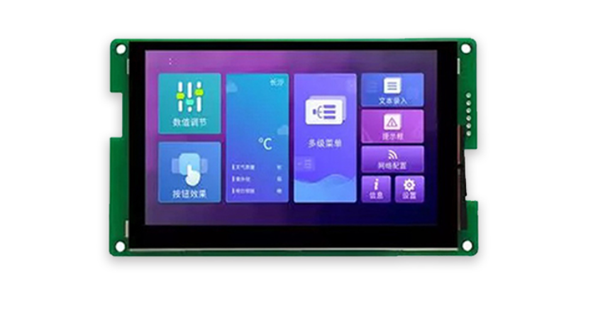
The display control part adopts Devon's 4.3-inch serial port screen.
- Front view:
- Back view:
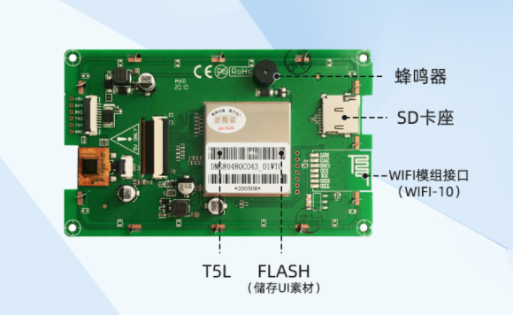
- Interface diagram:

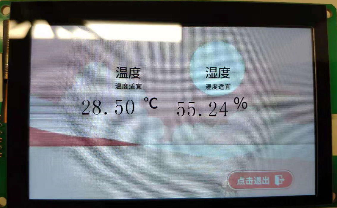
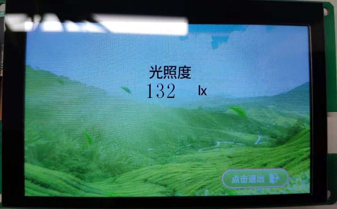
The interface effect of interface design in this design is shown in the figure below:
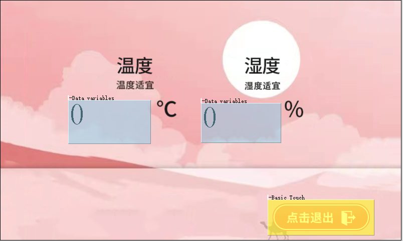
- Temperature and humidity interface effect display:
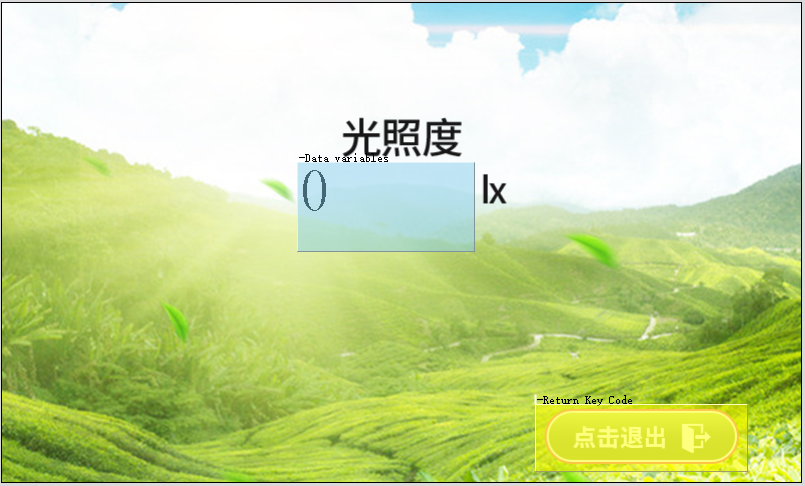
- Illumination interface effect display:
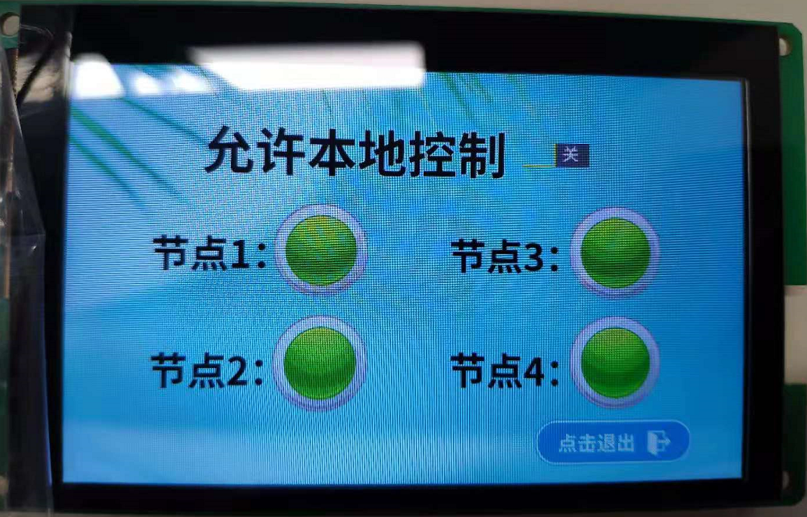
- Display of control interface effect:
MCU and display screen communicate through serial port to realize control and display.
2, Devon screen interface and program design
STM32 communicates with Devon screen through serial port 1, with a baud rate of 115200.
1. Interface design
First, use PS software to make the pictures you need, and then save them into BMP picture format with 800 * 480 resolution. Then, a host computer software of Devon is used for display and control design. How to design reference
Official data of Devon: T5L DGUSII application development guide.
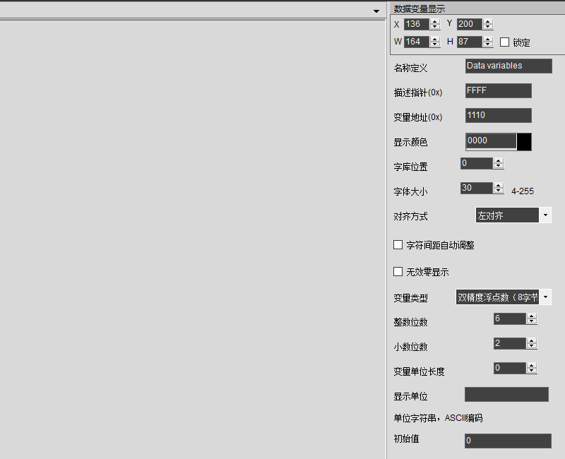
- Temperature and humidity interface:
- Illuminance interface:
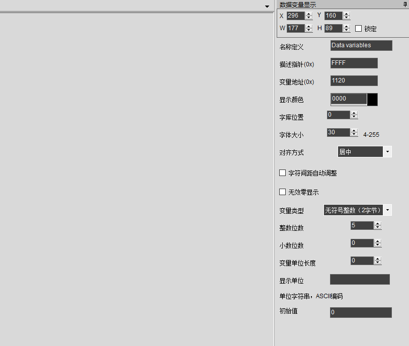
- Node control interface:
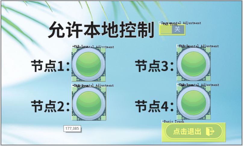
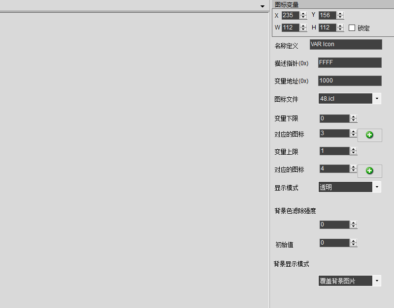
Complete project of control panel interface design: Click here to download
2. Driver design
- Call WriteDataToLCD to write data to the serial port screen:
/*******************************************************************************
** Function Name  :void WriteDataToLCD(uint16_t startAddress,uint16_t return_data_start_addr,uint16_t length)
** Description    : Data is written to the touch screen variable register
** Input          : uint16_t startAddress,uint16_t return_data_start_addr,uint16_t length
** Output         : None
** Return         : None
** Attention            :
*******************************************************************************/
void WriteDataToLCD(uint16_t startAddress,uint16_t return_data_start_addr,uint16_t length)
{
  /*The length of the command consists of frame header (2 bytes) + data length (1 byte) + instruction (1 byte) + starting address (2 bytes) + data (length)*/
    uint8_t i;
    usart1_txBuf[0]=0x5a;
    usart1_txBuf[1]=0xa5;
    usart1_txBuf[2]=length+3;
    usart1_txBuf[3]=0x82;
    usart1_txBuf[4]=(uint8_t)((startAddress>>8)&0xff);//Start address
    usart1_txBuf[5]=(uint8_t)(startAddress&0XFF);//Start address
    for(i=0;i<length;i++)
    {
        usart1_txBuf[i+6]=((SEND_BUF[i+return_data_start_addr]));
    }
    HAL_UART_Transmit(&huart1, usart1_txBuf, length+6, 20);
}- Call ReadDataFromLCD to read serial port screen data:
/*******************************************************************************
** Function Name :void ReadDataFromLCD(uint16_t startAddress,uint8_t readWordLength)
** Description : Read variable memory data
** Input : uint16_t startAddress,uint8_t readWordLength
** Output : None
** Return : None
** Attention :
*******************************************************************************/
void ReadDataFromLCD(uint16_t startAddress,uint16_t readWordLength)
{
//The length of command consists of frame header (2 bytes) + data length (1 byte) + instruction (1 byte) + starting address (2 bytes) + read word length (1 byte)
usart1_txBuf[0]=0x5a;
usart1_txBuf[1]=0xa5;
usart1_txBuf[2]=0x04;
usart1_txBuf[3]=0x83;
usart1_txBuf[4]=(uint8_t)((startAddress>>8)&0xff);//Start address
usart1_txBuf[5]=(uint8_t)(startAddress&0xff);//Start address
usart1_txBuf[6]=readWordLength;//Read length
HAL_UART_Transmit(&huart1, usart1_txBuf, 7 , 20);
}- Call void send_tz control page Jump:
-
/******************************************************************************* ** Function Name :void send_tz(void)) ** Description : Jump page function ** Input : None ** Output : None ** Return : None ** Attention : *******************************************************************************/ void send_tz(void) { uint8_t i; usart1_txBuf[0]=0x5a; usart1_txBuf[1]=0xa5; usart1_txBuf[2]=0x07; usart1_txBuf[3]=0x82; usart1_txBuf[4]=0x00; usart1_txBuf[5]=0x84; usart1_txBuf[6]=0x5a; usart1_txBuf[7]=0x01; for(i=0;i<2;i++) { usart1_txBuf[i+8]=((SEND_BUF[i])); } HAL_UART_Transmit(&huart1, usart1_txBuf, 10, 20); }
3.STM32 communicates with serial port screen
(1) Function introduction
- Serial port screen and APP display:
After reading the temperature, humidity and illumination data, the single chip microcomputer sends the data to the serial port screen and APP, which display the data of these sensors in real time.
void Deal_Data_Display(void)
{
uint8_t i;
uint16_t light;
double Tem_val,Hum_val;
uint8_t dat[2] = {0};
uint8_t Buffer[30]={0};
HAL_Delay(1000);
if(SHT3x_Get_Humiture_periodic(&Tem_val,&Hum_val) == 0)
{
memcpy(Buffer,(double*)(&Tem_val),8);
memcpy(Buffer+8,(double*)(&Hum_val),8);
for(i=0;i<8;i++)
{
SEND_BUF[i] = Buffer[7-i];
}
WriteDataToLCD(0X1110,0,8);
for(i=0;i<8;i++)
{
SEND_BUF[i] = Buffer[15-i];
}
WriteDataToLCD(0X1118,0,8);
mcu_dp_value_update(DPID_TEMPERATURE,Tem_val*100); //Temperature data reporting;
mcu_dp_value_update(DPID_HUMIDITY,Hum_val*100); //Humidity data reporting;
printf("temperature=%6.2lf,humidity=%6.2lf\r\n",Tem_val,Hum_val);
}
else
printf("Get_Humiture ERR\r\n");
HAL_Delay(180);
if(HAL_OK == BH1750_Read_Dat(dat))
{
light=BH1750_Dat_To_Lx(dat);
memcpy(Buffer+16, (uint16_t*)(&light), sizeof((uint16_t*)(&light)));
for(i=0;i<2;i++)
{
SEND_BUF[i] = Buffer[17-i];
}
WriteDataToLCD(0X1120,0,2);
delay_ms(5);
printf("illuminance: %5d lx\r\n", light);
mcu_dp_value_update(DPID_ILLUMINANCE,light*100); //Illuminance data reporting;
}
else
{
printf("recv fail");
}
}
- Serial port panel control GPIO port level:
Flip the IO level in the interrupt processing function of serial port 1. You can rewrite this function and try not to process more data in the interrupt processing function.
void USART1_IRQHandler(void)
{
    uint8_t usart1_data;
    uint8_t send[2]={0x5a,0xa5};
    uint16_t addr=0,data=0;//Define address and data
    //uint16_t len=0;       // Define length
  uint8_t usart1_counter=0;
  if((USART1->ISR & 1<<5) == 1<<5)//Receive register data is not empty
    {
        usart1_data=USART1->RDR;
    usart1_rxBuf[usart1_counter] = usart1_data;
    if(usart1_counter < 2)
    {
        if(usart1_rxBuf[usart1_counter]==send[usart1_counter])
        {
            usart1_counter++;
        }
        else
        {
            usart1_counter=0;
        }
    }
    else
    {
        usart1_counter++;
    }
    if(usart1_counter>=(usart1_rxBuf[2]+3))
    {
            addr = usart1_rxBuf[4]*256+usart1_rxBuf[5];             //Get lcd control register address
            //len =  usart1_rxBuf[6];                                                   // Gets the number of data words received
            data = usart1_rxBuf[7]*256+usart1_rxBuf[8];             //Gets the value of the first word data
        switch(addr)
         {
             case 0x1000:
                 if(data==0x01)
                  {
                   HAL_GPIO_WritePin(GPIOC, GPIO_PIN_2, GPIO_PIN_SET);
                  }
                else if(data==0x00)
                  {
                     HAL_GPIO_WritePin(GPIOC, GPIO_PIN_2, GPIO_PIN_RESET);
                  }
                        break;
       case 0x1001:
                    if(data==0x01)
                        {
                         HAL_GPIO_WritePin(GPIOC, GPIO_PIN_6, GPIO_PIN_SET);
                        }
                    else if(data==0x00)
                     {
                         HAL_GPIO_WritePin(GPIOC, GPIO_PIN_6, GPIO_PIN_RESET);
                     }
                break;
           case 0x1002:
                    if(data==0x01)
                    {
                     HAL_GPIO_WritePin(GPIOC, GPIO_PIN_7, GPIO_PIN_SET);
                    }
               else if(data==0x00)
                {
                    HAL_GPIO_WritePin(GPIOC, GPIO_PIN_7, GPIO_PIN_RESET);
                }
                break;
            case 0x1003:
                    if(data==0x01)
                    {
                     HAL_GPIO_WritePin(GPIOC, GPIO_PIN_8, GPIO_PIN_SET);
                    }
               else if(data==0x00)
                {
                    HAL_GPIO_WritePin(GPIOC, GPIO_PIN_8, GPIO_PIN_RESET);
                }
                break;
      default :
                        break;
           }
      usart1_counter=0;
    }
 }
    if((USART1->ISR & (1<<3)) == (1<<3))//ORE
    {
        USART1->ICR =1<<3;
    }
}- APP control:
Call the following DP processing functions to control the serial port screen and GPIO by APP:
/*****************************************************************************
Function name: dp_download_switch_1_handle
Function Description: for dpid_ SWITCH_ Handler for 1
Input parameter: value: data source data
: length:Data length
Return parameters: SUCCESS return: SUCCESS / Failure Return: ERROR
Instructions: you can distribute the reportable type. You need to report the processing results to the app after processing the data
*****************************************************************************/
static unsigned char dp_download_switch_1_handle(const unsigned char value[], unsigned short length)
{
//Example: the current DP type is BOOL
unsigned char ret;
//0: off / 1: on
unsigned char switch_1;
switch_1 = mcu_get_dp_download_bool(value,length);
if(switch_1 == 0)
{
//Switch off
SEND_BUF[0]=0x00;
SEND_BUF[1]=0x06;
send_tz();
SEND_BUF[0]=0x00;
SEND_BUF[1]=0x00;
WriteDataToLCD(0x1000,0,2);
HAL_GPIO_WritePin(GPIOC, GPIO_PIN_2, GPIO_PIN_RESET);
}
else
{
SEND_BUF[0]=0x00;
SEND_BUF[1]=0x06;
send_tz();
SEND_BUF[0]=0x00;
SEND_BUF[1]=0x01;
WriteDataToLCD(0x1000,0,2);
HAL_GPIO_WritePin(GPIOC, GPIO_PIN_2, GPIO_PIN_SET);
//Switch on
}
//Feedback shall be provided after processing DP data
ret = mcu_dp_bool_update(DPID_SWITCH_1,switch_1);
if(ret == SUCCESS)
return SUCCESS;
else
return ERROR;
}
/*****************************************************************************
Function name: dp_download_switch_2_handle
Function Description: for DPID_SWITCH_2 processing function
Input parameter: value: data source data
: length:Data length
Return parameters: SUCCESS return: SUCCESS / Failure Return: ERROR
Instructions: you can distribute the reportable type. You need to report the processing results to the app after processing the data
*****************************************************************************/
static unsigned char dp_download_switch_2_handle(const unsigned char value[], unsigned short length)
{
//Example: the current DP type is BOOL
unsigned char ret;
//0: off / 1: on
unsigned char switch_2;
switch_2 = mcu_get_dp_download_bool(value,length);
if(switch_2 == 0) {
SEND_BUF[0]=0x00;
SEND_BUF[1]=0x06;
send_tz();
SEND_BUF[0]=0x00;
SEND_BUF[1]=0x00;
WriteDataToLCD(0x1001,0,2);
HAL_GPIO_WritePin(GPIOC, GPIO_PIN_6, GPIO_PIN_RESET);
//Switch off
}else {
SEND_BUF[0]=0x00;
SEND_BUF[1]=0x06;
send_tz();
SEND_BUF[0]=0x00;
SEND_BUF[1]=0x01;
WriteDataToLCD(0x1001,0,2);
HAL_GPIO_WritePin(GPIOC, GPIO_PIN_6, GPIO_PIN_SET);
//Switch on
}
//Feedback shall be provided after processing DP data
ret = mcu_dp_bool_update(DPID_SWITCH_2,switch_2);
if(ret == SUCCESS)
return SUCCESS;
else
return ERROR;
}
/*****************************************************************************
Function name: dp_download_switch_3_handle
Function Description: for dpid_ SWITCH_ Processing function of 3
Input parameter: value: data source data
: length:Data length
Return parameters: SUCCESS return: SUCCESS / Failure Return: ERROR
Instructions: you can distribute the reportable type. You need to report the processing results to the app after processing the data
*****************************************************************************/
static unsigned char dp_download_switch_3_handle(const unsigned char value[], unsigned short length)
{
//Example: the current DP type is BOOL
unsigned char ret;
//0: off / 1: on
unsigned char switch_3;
switch_3 = mcu_get_dp_download_bool(value,length);
if(switch_3 == 0) {
SEND_BUF[0]=0x00;
SEND_BUF[1]=0x06;
send_tz();
SEND_BUF[0]=0x00;
SEND_BUF[1]=0x00;
WriteDataToLCD(0x1002,0,2);
HAL_GPIO_WritePin(GPIOC, GPIO_PIN_7, GPIO_PIN_RESET);
//Switch off
}else {
SEND_BUF[0]=0x00;
SEND_BUF[1]=0x06;
send_tz();
SEND_BUF[0]=0x00;
SEND_BUF[1]=0x01;
WriteDataToLCD(0x1002,0,2);
HAL_GPIO_WritePin(GPIOC, GPIO_PIN_7, GPIO_PIN_SET);
//Switch on
}
//Feedback shall be provided after processing DP data
ret = mcu_dp_bool_update(DPID_SWITCH_3,switch_3);
if(ret == SUCCESS)
return SUCCESS;
else
return ERROR;
}
/*****************************************************************************
Function name: dp_download_switch_4_handle
Function Description: for dpid_ SWITCH_ Processing function of 4
Input parameter: value: data source data
: length:Data length
Return parameters: SUCCESS return: SUCCESS / Failure Return: ERROR
Instructions: you can distribute the reportable type. You need to report the processing results to the app after processing the data
*****************************************************************************/
static unsigned char dp_download_switch_4_handle(const unsigned char value[], unsigned short length)
{
//Example: the current DP type is BOOL
unsigned char ret;
//0: off / 1: on
unsigned char switch_4;
switch_4 = mcu_get_dp_download_bool(value,length);
if(switch_4 == 0) {
SEND_BUF[0]=0x00;
SEND_BUF[1]=0x06;
send_tz();
SEND_BUF[0]=0x00;
SEND_BUF[1]=0x00;
WriteDataToLCD(0x1003,0,2);
HAL_GPIO_WritePin(GPIOC, GPIO_PIN_8, GPIO_PIN_RESET);
//Switch off
}else {
SEND_BUF[0]=0x00;
SEND_BUF[1]=0x06;
send_tz();
SEND_BUF[0]=0x00;
SEND_BUF[1]=0x01;
WriteDataToLCD(0x1003,0,2);
HAL_GPIO_WritePin(GPIOC, GPIO_PIN_8, GPIO_PIN_SET);
//Switch on
}
//Feedback shall be provided after processing DP data
ret = mcu_dp_bool_update(DPID_SWITCH_4,switch_4);
if(ret == SUCCESS)
return SUCCESS;
else
return ERROR;
}(2) Main program design
The main function loop body calls the networking function, the WIFI serial port processes the function, and the data displays the function.
int main(void)
{
/* MCU Configuration--------------------------------------------------------*/
/* Reset of all peripherals, Initializes the Flash interface and the Systick.*/
HAL_Init();
/* Configure the system clock */
SystemClock_Config();
/* Initialize all configured peripherals */
MX_GPIO_Init();
MX_USART1_UART_Init();
MX_USART2_UART_Init();
MX_USART3_UART_Init();
wifi_protocol_init(); //wifi protocol initialization
MX_I2C2_Init();
MX_I2C1_Init();
MX_TIM3_Init(10000-1,8000-1); //Timer 3 initialization, timing 1s
SHT3x_Reset();
if( 0 == SHT3x_Init())
printf("SHT3x_Init OK \r\n");
else
printf("SHT3x_Init ERR \r\n");
/* Infinite loop */
/* USER CODE BEGIN WHILE */
while (1)
{
Connect_Wifi();
wifi_uart_service();//wifi serial port data processing service
if(1 == Display_Flag)
{
Deal_Data_Display();
Display_Flag=0;
}
}
}(3) How to reduce power consumption
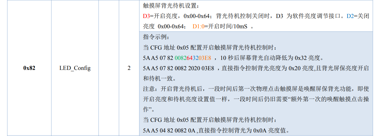
The backlight standby control of the touch screen can be carried out by command. For detailed instructions, refer to T5L DGUSII application development guide.
(4) Prototype physical display
The temperature, humidity and illuminance data are displayed in real time through APP and serial port screen, and the level reversal of GPIO can be controlled in real time by operating serial port screen and APP.
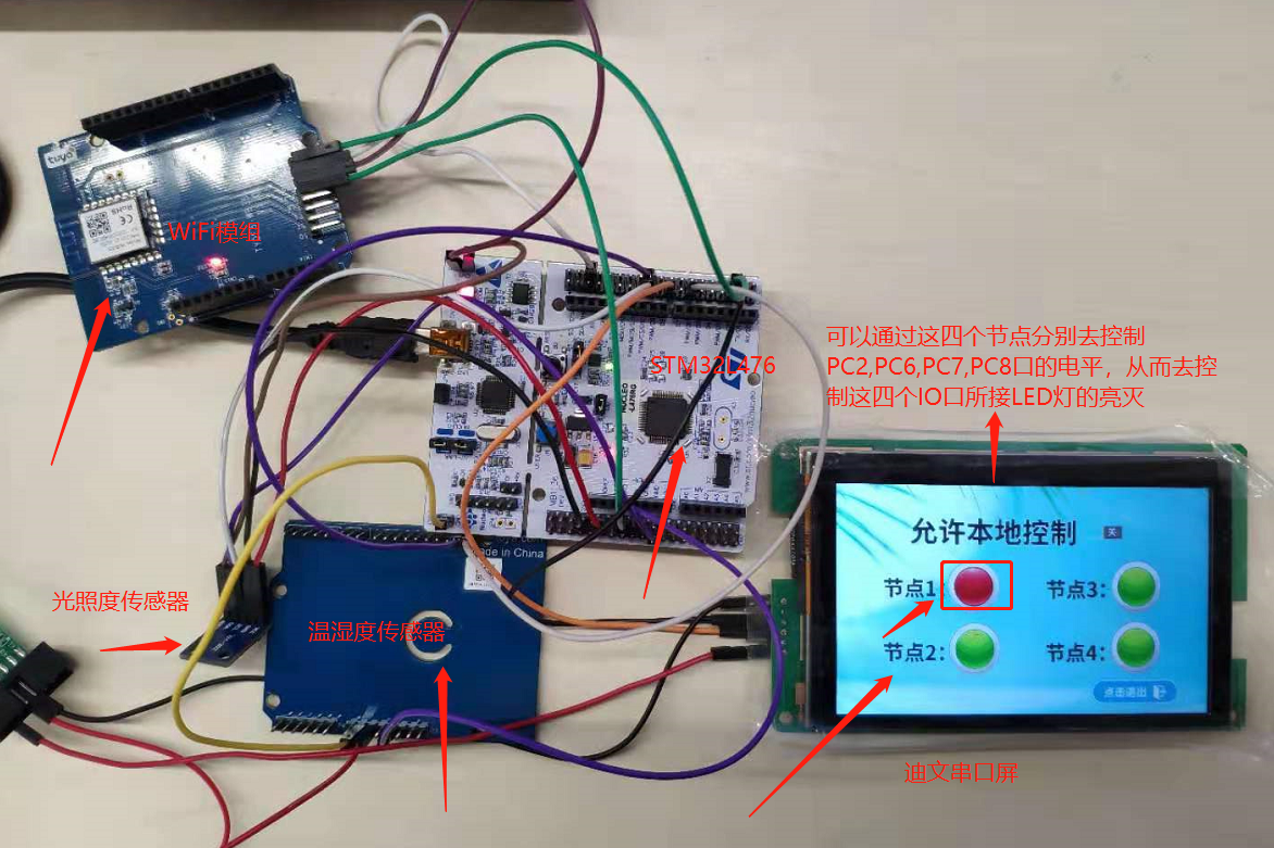
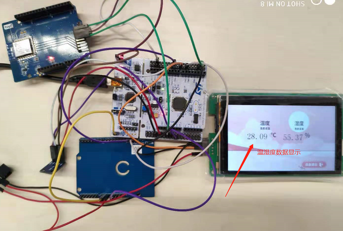
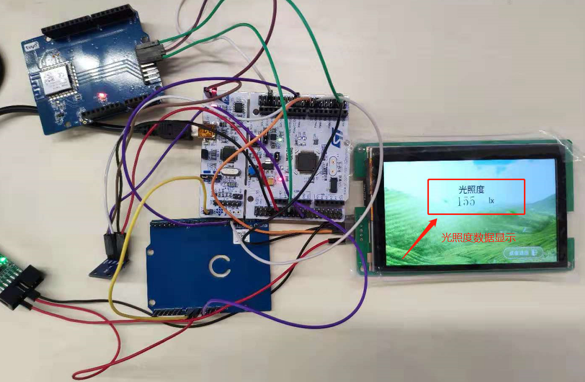
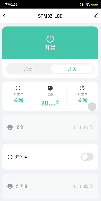
The level of serial port screen and GPIO port can be controlled through APP.