catalogue
Problem background
Stepper motor is an open-loop control element that converts electric pulse signal into angular displacement or linear displacement. It is only because of the function of driver that it is step-by-step evolved and digitized. Without overload, the speed and stop position of stepping motor only depend on the frequency and number of pulses of pulse signal, and are not limited by load. The starting and operation of stepping motor directly affects the stability and accuracy of digital control. Therefore, in the process of stepping motor control, it is necessary to effectively transition the acceleration operation stage to ensure the accurate and efficient operation of the motor. At present, the stepping motor drive technology mainly adopts chopper constant current control and sinusoidal pulse width modulation technology for motor control, which greatly improves the running speed and accuracy of the motor.
Based on many advantages of stepping motor, it has been widely used in many fields, such as industrial automation equipment, office automation equipment and so on, such as horizontal and vertical tool walking of NC machine tool, radial feed of inner circle slicer, printing of office supplies and so on. With the continuous development of science and technology, higher requirements are put forward for the control technology of stepping motor. Therefore, it has become an indisputable fact for the development of science and technology to explore a more comprehensive and more accurate stepping motor control method.
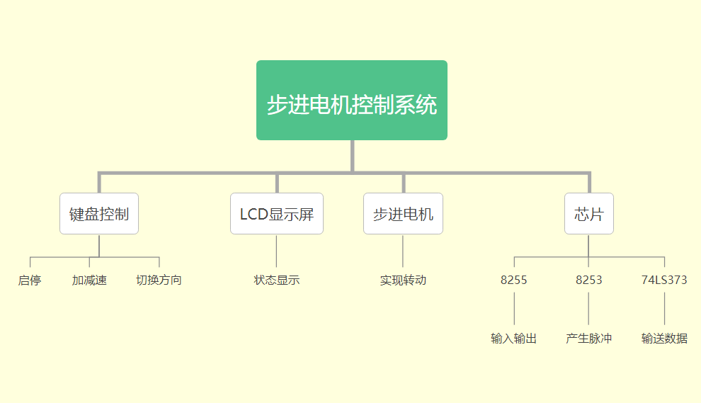
Functional module diagram
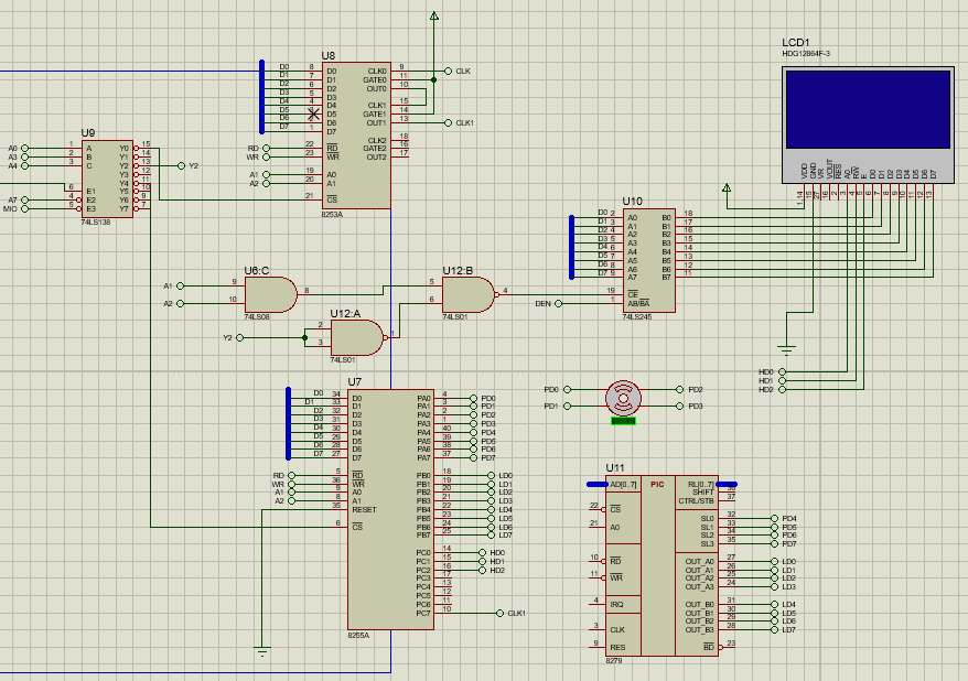
The circuit principle diagram
System function description
The stepping motor control system takes the 4 * 4 keyboard as the input port. After reading the command from the keyboard, it outputs it through port 8255A to make the stepping motor rotate. The rotation frequency of the motor is provided by the output pulse of 8253. After the motor rotates, the 74LS273 outputs to the LCD to make the LCD display the working state of the stepping motor. Press keys 1-9 to switch between different gears, press keys a and B to switch the rotation direction of the motor, press key C to stop the motor, and press key D to clear the LCD screen.
System algorithm design
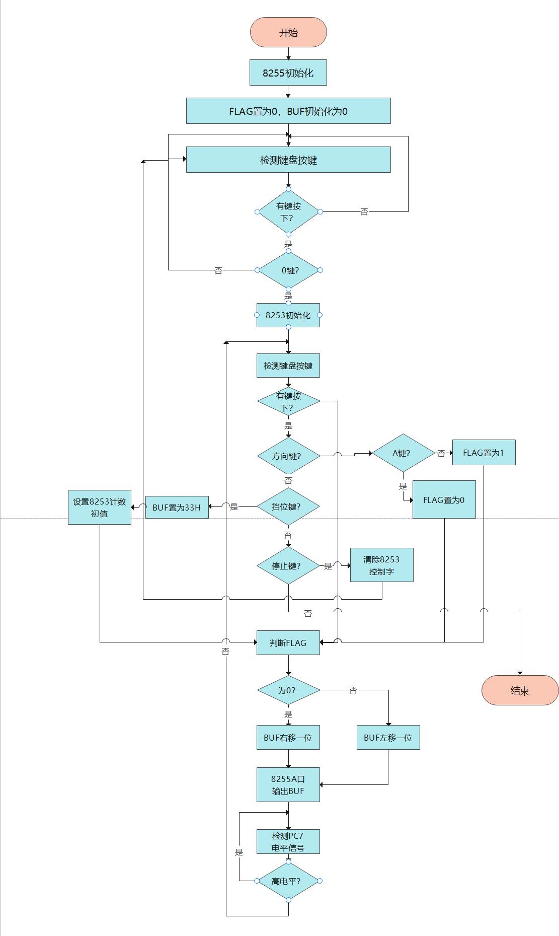
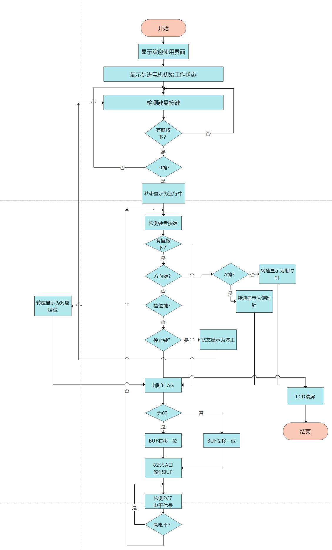
This experiment aims to realize more accurate control of stepping motor with keyboard. Firstly, start the system to initialize 8255, set the FLAG flag FLAG to select the rotation direction (start to set the FLAG to 0, and rotate counterclockwise by default), and then test whether there is a key pressed. When the 0 key is pressed, initialize 8253, input the control word, select channel 0 and channel 1, cascade the two channels, select mode 3, and then set the initial count value for the two channels. When the 1-9 key is pressed, set the BUF to 33H so that the stepper motor can rotate, and then reset the initial count values of the two channels. Keys 1-9 correspond to different initial counting values, so that 8253 can generate pulses of different frequencies. Then, the 8255A port outputs BUF to start the stepping motor. The 74LS273 outputs data to the LCD every step of rotation to make the LCD display the current working state of the stepping motor. Then test whether the key is pressed. If the gear key is pressed, the shift can be realized by resetting the initial count value to 8253. After pressing the direction key, the rotation direction can be switched. When the C key is pressed, the 8253 control word is cleared and the motor stops. When the D key is pressed, the LCD clears.
Program flow chart
Stepper motor module
lcm
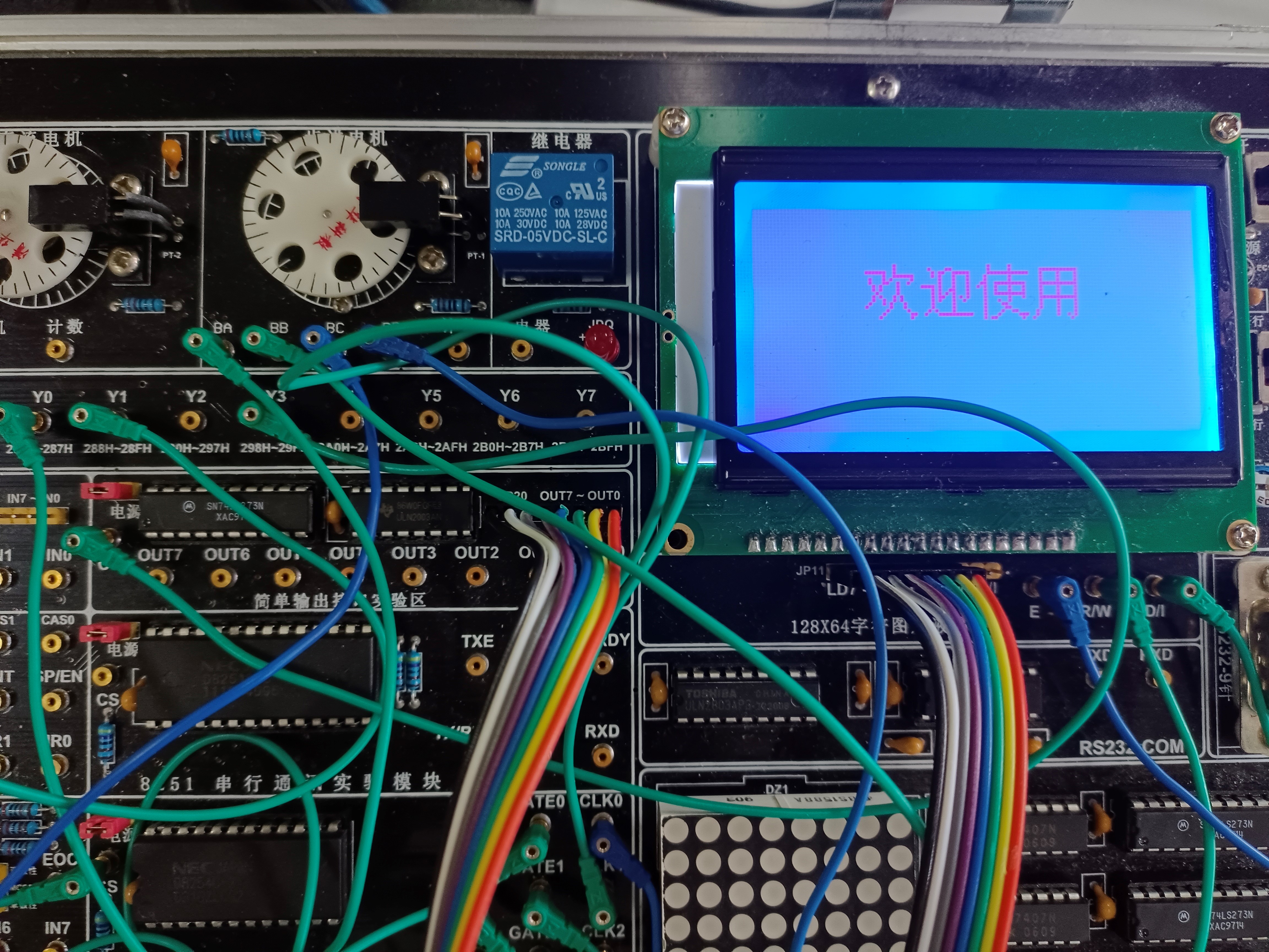
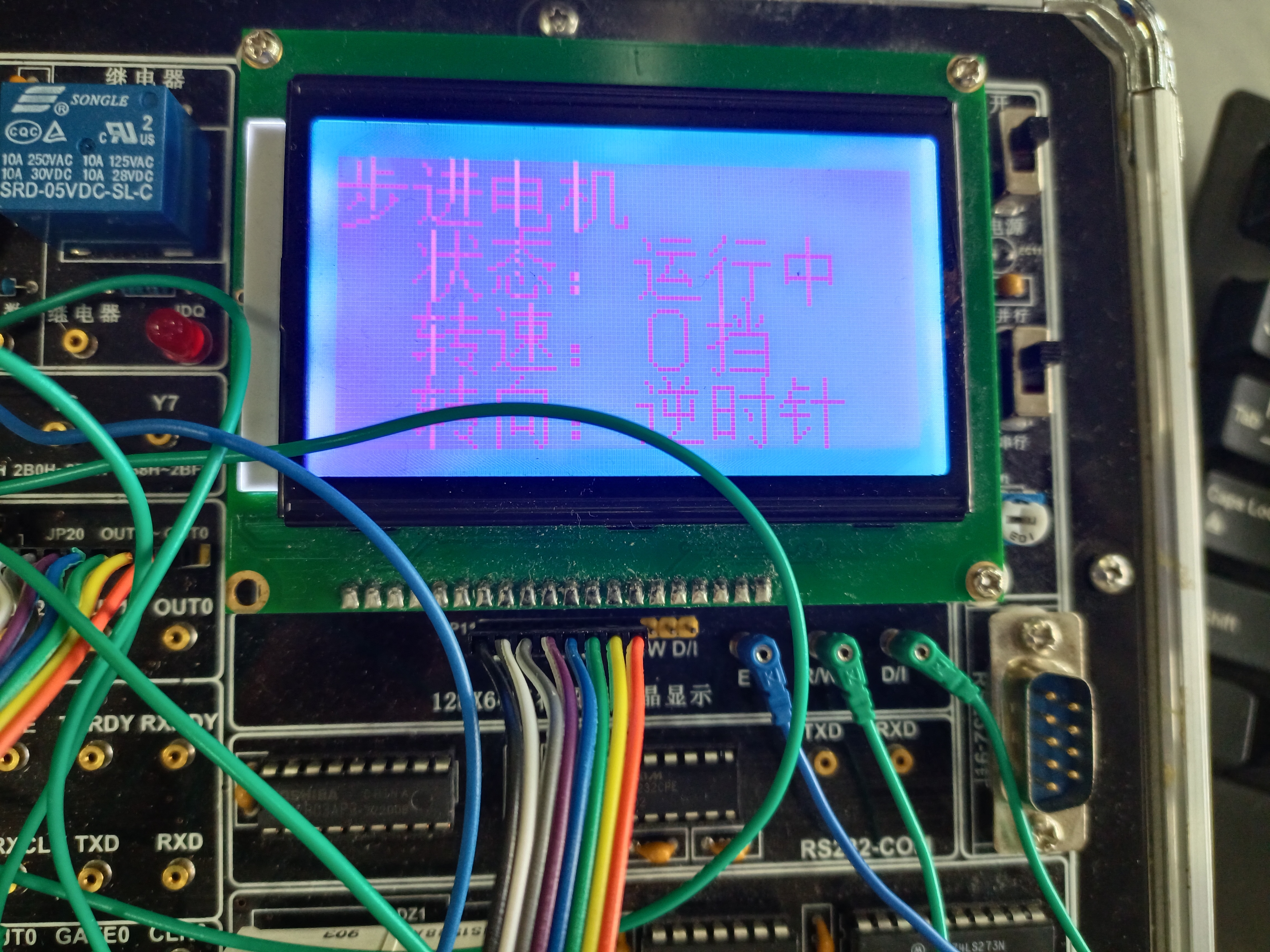
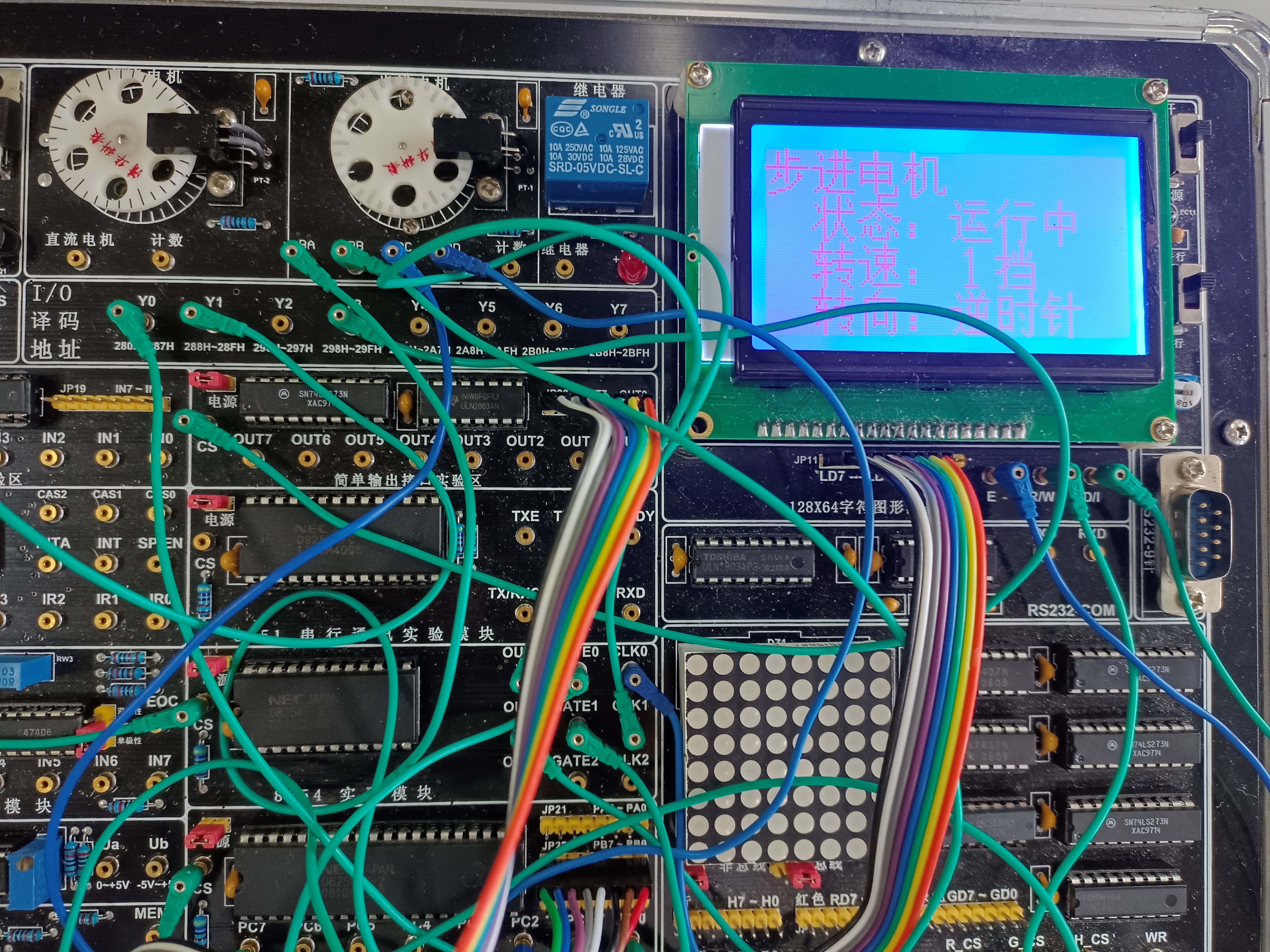
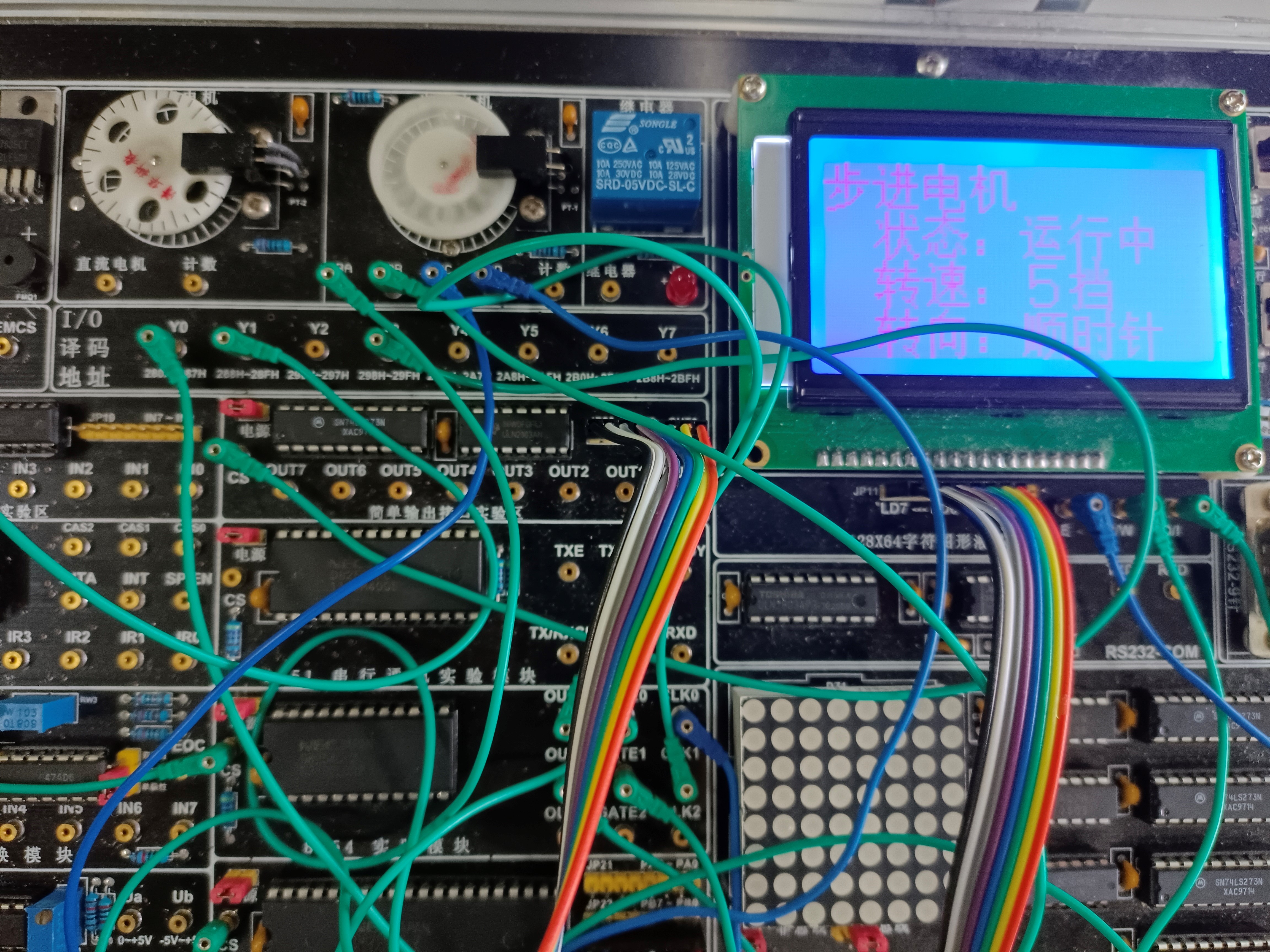
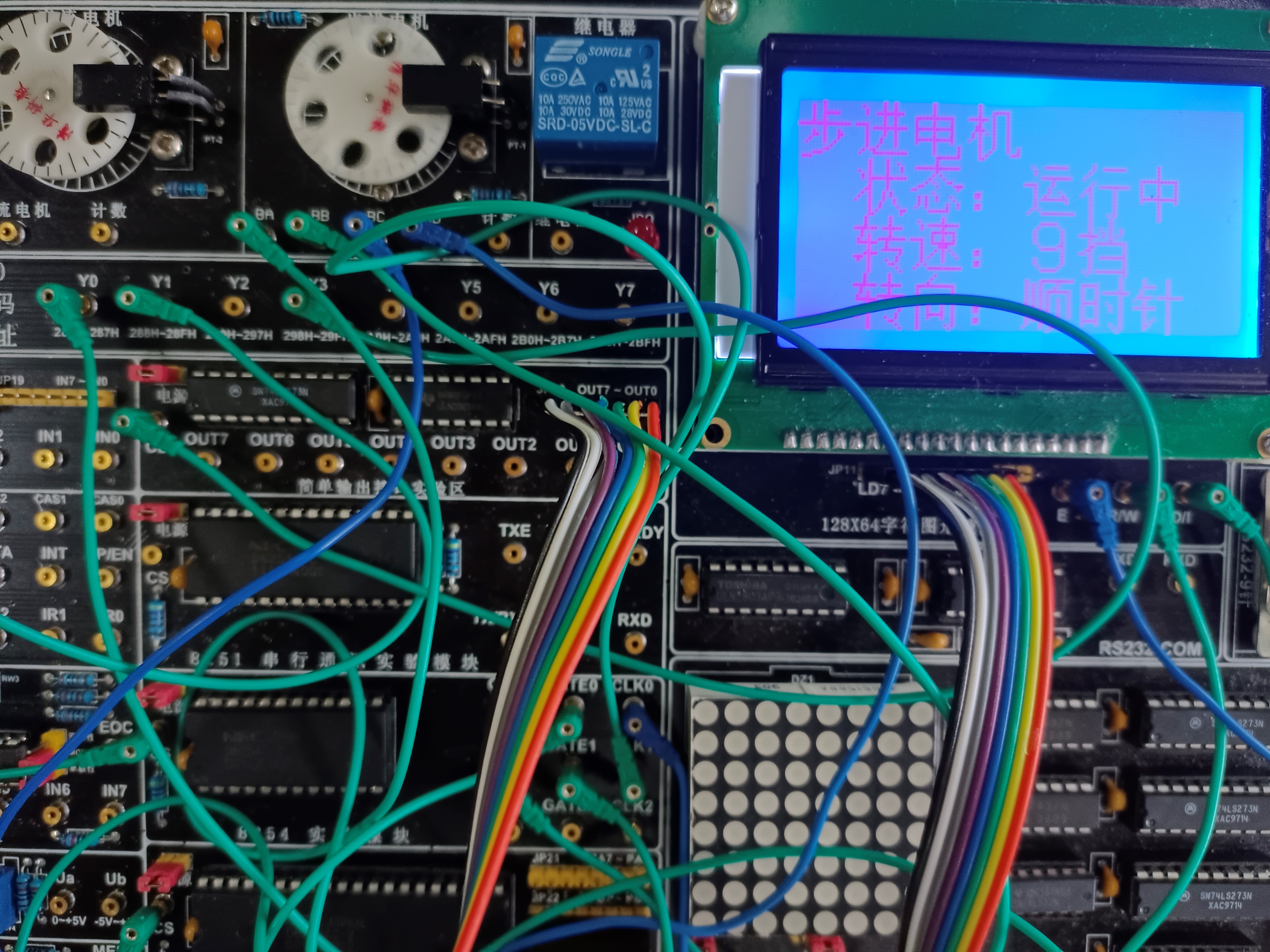
Running screenshot
functional testing
| modular | Test input | Expected results | Measured results |
|
The keyboard controls the rotation of the stepping motor | Press the 0 key | Stepper motor start | Consistent with expected results |
| Press the 1 key | The stepper motor rotates slowly | Consistent with expected results | |
| Press the 3 key | The stepper motor rotates at a slower speed | Consistent with expected results | |
| Press the 5 key | Stepper motor rotates at medium speed | Consistent with expected results | |
| Press the 7 key | The stepper motor rotates at a higher speed | Consistent with expected results | |
| Press the 9 key | High speed rotation of stepping motor | Consistent with expected results | |
| Press the A key | The stepping motor rotates counterclockwise | Consistent with expected results | |
| Press the B key | The stepper motor rotates clockwise | Consistent with expected results | |
| Press the C key | The stepping motor stops rotating | Consistent with expected results | |
| LCD displays the working state of stepping motor | Press the 0 key | The LCD shows that the motor status is running | Consistent with expected results |
| Press the 1 key | LCD shows that the motor speed is 1st gear | Consistent with expected results | |
| Press the 2 key | LCD shows that the motor speed is 2nd gear | Consistent with expected results | |
| Press the 3 key | The LCD shows that the motor speed is gear 3 | Consistent with expected results | |
| Press the 4 key | LCD shows that the motor speed is 4th gear | Consistent with expected results | |
| Press the 5 key | LCD shows that the motor speed is 5th gear | Consistent with expected results | |
| Press the 6 key | LCD shows that the motor speed is 6 gears | Consistent with expected results | |
| Press the 7 key | LCD shows that the motor speed is 7 gears | Consistent with expected results | |
| Press the 8 key | LCD shows that the motor speed is 8 gears | Consistent with expected results | |
| Press the 9 key | LCD shows that the motor speed is 9 gears | Consistent with expected results | |
| Press the A key | The LCD shows that the motor turns counterclockwise | Consistent with expected results | |
| Press the B key | The LCD shows that the motor turns clockwise | Consistent with expected results | |
| Press the C key | The LCD shows that the motor status is stopped | Consistent with expected results | |
| Press the D key | LCD clear screen | Consistent with expected results |
Assembly source code
PORT_A EQU 280H
PORT_B EQU 281H
PORT_C EQU 282H
PORT_CTL1 EQU 283H
PORT_L0 EQU 288H
PORT_L1 EQU 289H
PORT_L2 EQU 28AH
PORT_CTL2 EQU 28BH
PORT_273 EQU 298H
DATA SEGMENT
BUF   DB  0
FLAG  DB  0
;         0   1   2   3   4    5    6    7
TABLE DB 77H,7BH,7DH,7EH,0B7H,0BBH,0BDH,0BEH
;         8    9    A    B    C    D    E    F
      DB 0D7H,0DBH,0DDH,0DEH,0E7H,0EBH,0EDH,0EEH
HZ_ADR   DB 00H    ;Start port address of storage display line
INIT_WELCOME DW 0A1A0H,0A1A0H,0A1A0H,0A1A0H,0A1A0H,0A1A0H,0A1A0H,0A1A0H
    DW 0A1A0H,0A1A0H,0BBB6H,0D3ADH,0CAB9H,0D3C3H,0A1A0H,0A1A0H
    DW 0A1A0H,0A1A0H,0A1A0H,0A1A0H,0A1A0H,0A1A0H,0A1A0H,0A1A0H
    DW 0A1A0H,0A1A0H,0A1A0H,0A1A0H,0A1A0H,0A1A0H,0A1A0H,0A1A0H

SHOW DW 0B2BDH,0BDF8H,0B5E7H,0BBFAH,0A1A0H,0A1A0H,0A1A0H,0A1A0H
     DW 0A1A0H,0D7B4H,0CCACH,0A3BAH,0CDA3H,0D6B9H,0A1A0H,0A1A0H
     DW 0A1A0H,0D7AAH,0CBD9H,0A3BAH,0A3B0H,0B5B2H,0A1A0H,0A1A0H
     DW 0A1A0H,0D7AAH,0CFF2H,0A3BAH,0C4E6H,0CAB1H,0D5EBH,0A1A0H

CLEAR1 DW 0A1A0H,0A1A0H,0A1A0H,0A1A0H,0A1A0H,0A1A0H,0A1A0H,0A1A0H
      DW 0A1A0H,0A1A0H,0A1A0H,0A1A0H,0A1A0H,0A1A0H,0A1A0H,0A1A0H
      DW 0A1A0H,0A1A0H,0A1A0H,0A1A0H,0A1A0H,0A1A0H,0A1A0H,0A1A0H
      DW 0A1A0H,0A1A0H,0A1A0H,0A1A0H,0A1A0H,0A1A0H,0A1A0H,0A1A0H
DATA ENDS
STACKS    SEGMENT
          DB 2560 DUP(?)
STACKS    ENDS
CODE      SEGMENT
          ASSUME CS:CODE,DS:DATA,SS:STACKS,ES:DATA

;-------------------LCD12864 Control command macro OK------------------------
CMD_SETUP MACRO      ; LCD Command settings
    MOV DX,PORT_C    ; Point to 8255 control port C
    NOP
    MOV AL,00000000B ; PC1 Set 0,pc0 Set 0( LCD W end=0,I end=0)
    OUT DX, AL
    NOP
    MOV AL,00000100B ; PC2 Set 1( LCD E end=1)
    OUT DX, AL
    NOP
    MOV AL,00000000B ; PC2 Set 0,(LCD E end=0)
    OUT DX, AL
    NOP
ENDM
;-------------------LCD12864 Write data macro OK------------------------
DATA_SETUP MACRO     ; LCD Write data
    MOV DX,PORT_C    ; Point to 8255 control port C
    MOV AL,00000001B ; PC1 Set to 0, PC0=1 (LCD I end=1)
    OUT DX,AL
    NOP
    MOV AL,00000101B ; PC2 Set 1( LCD E end=1)
    OUT DX,AL
    NOP
    MOV AL,00000001B ; PC2 Set 0,(LCD E end=0)
    OUT DX,AL
    NOP
ENDM
;-------------------LCD12864 Display character OK------------------------
STRING_SHOW MACRO INT_N
    LOCAL CONTINUE1
    ;Several Chinese characters are displayed in one line, INT_N As parameter
    MOV CL,INT_N
CONTINUE1:
    PUSH CX
    MOV AL,HZ_ADR
    MOV DX, PORT_273 ;for the first time, pa0=0
    OUT DX, AL
    CMD_SETUP ; set up DDRAM Address command
    MOV AX,[BX]
    PUSH AX
    MOV AL,AH ; Send Chinese character code first
    MOV DX,PORT_273
    OUT DX,AL
    DATA_SETUP ; Output Chinese character encoding high byte
    POP AX
    MOV DX,PORT_273
    OUT DX, AL
    DATA_SETUP ; Output Chinese character encoding low byte
    INC BX
    INC BX ; Modify the pointer to the display inner code buffer
    INC BYTE PTR HZ_ADR ; modify LCD Display port address HZ_ADR Is a byte unit
    POP CX
    DEC CL
    JNZ  CONTINUE1
ENDM
START:
  MOV AX,DATA
  MOV DS,AX
  MOV DX,PORT_CTL1
  MOV AL,8AH
  OUT DX,AL
  MOV AL,00H
  MOV FLAG,AL
  CALL BEGIN
  CALL DELAY3
  CALL DELAY3
  CALL DELAY3
  CALL DELAY3
  CALL DELAY3
  CALL DELAY3
  CALL DELAY3
  CALL DELAY3
  CALL DELAY3
  CALL DELAY3
  CALL DELAY3
  CALL NEXT
  MOV DX,PORT_CTL2
  MOV AL,37H
  OUT DX,AL
  MOV AL,77H
  OUT DX,AL
  MOV DX,PORT_L0
  MOV AL,20H
  OUT DX,AL
  MOV AL,00H
  OUT DX,AL
  MOV DX,PORT_L1
  MOV AL,20H
  OUT DX,AL
  MOV AL,00H
  OUT DX,AL

KEY:
  MOV DX,PORT_A
  MOV AL,00H
  OUT DX,AL
  MOV DX,PORT_B
WAIT_OPEN:
  IN AL,DX
  AND AL,0FH
  CMP AL,0FH
  JNE WAIT_OPEN
WAIT_PRES:
  IN AL,DX
  AND AL,0FH
  CMP AL,0FH
  JE STE1
  MOV CX,00EAH
DELAY:LOOP DELAY
  IN AL,DX
  AND AL,0FH
  CMP AL,0FH
  JE STE1
  MOV AL,0FEH
  MOV CL,AL
NEXT_ROW:
  MOV DX,PORT_A
  OUT DX,AL
  MOV DX,PORT_B
  IN AL,DX
  AND AL,0FH
  CMP AL,0FH
  JNE ENCODE
  ROL CL,01
  MOV AL,CL
  JMP NEXT_ROW
ENCODE:
  MOV BX,000FH
  IN AL,DX
NEXT_TRY:
  CMP AL,TABLE[BX]
  JE DONE
  DEC BX
  JNS NEXT_TRY
  MOV AH,01
  JMP EXIT
DONE:
  MOV AL,BL
  MOV AH,00
  JMP KEY_TEST
EXIT:HLT
STE1:
  JMP FLAG_TEST
KEY_TEST:
  CMP AL,00H
  JZ  ST0
  CMP AL,01H
  JZ  ST1
  CMP AL,02H
  JZ  ST2
  CMP AL,03H
  JZ  ST3
  CMP AL,04H
  JZ  ST4
  CMP AL,05H
  JZ  ST5
  CMP AL,06H
  JZ  ST6
  CMP AL,07H
  JZ  ST7
  CMP AL,08H
  JZ  ST8
  CMP AL,09H
  JZ  ST9
  CMP AL,0AH
  JZ  STA
  CMP AL,0BH
  JZ  STB
  CMP AL,0CH
  JZ  STC1
  CMP AL,0DH
  JZ STD1
ST3:
  JMP KEY_3
ST4:
  JMP KEY_4
ST7:
  JMP KEY_7
ST8:
  JMP KEY_8
ST9:
  JMP KEY_9
STA:
  JMP KEY_A
STB:
  JMP KEY_B
STC1:
  JMP KEY_C
ST5:
  JMP KEY_5
ST6:
  JMP KEY_6
ST2:
  JMP KEY_2
STD1:
  JMP KEY_D
ST0:
  JMP KEY_0
ST1:
  JMP KEY_1
FLAG_TEST:
  MOV AL,FLAG
  TEST AL,01H
  JNZ FLAG_1
  JMP FLAG_0
FLAG_0:
  MOV  AL,BUF
  ROR  AL,1
  MOV  BUF,AL
  MOV AL,9CH
  MOV DX, PORT_273
  OUT DX, AL
  CMD_SETUP
  CALL DELAY4
  MOV AX,0C4E6H
  PUSH AX
  MOV AL,AH
  MOV DX,PORT_273
  OUT DX,AL
  DATA_SETUP
  CALL DELAY4
  POP AX
  MOV DX,PORT_273
  OUT DX, AL
  DATA_SETUP
  CALL DELAY4
  JMP OUT1
FLAG_1:
  MOV  AL,BUF
  ROL  AL,1
  MOV  BUF,AL
  MOV AL,9CH
  MOV DX, PORT_273
  OUT DX, AL
  CMD_SETUP
  CALL DELAY4
  MOV AX,0CBB3H
  PUSH AX
  MOV AL,AH
  MOV DX,PORT_273
  OUT DX,AL
  DATA_SETUP
  CALL DELAY4
  POP AX
  MOV DX,PORT_273
  OUT DX, AL
  DATA_SETUP
  CALL DELAY4
  JMP OUT1
OUT1:
   MOV AL,BUF
   MOV DX,PORT_A
   OUT DX,AL
   MOV DX,PORT_C
TEMP:
   IN  AL,DX
   TEST AL,80H
   JZ TEMP
   JMP KEY
KEY_0:
  MOV AL,94H
  MOV DX, PORT_273
  OUT DX, AL
  CMD_SETUP
  CALL DELAY4
  MOV AX,0D4CBH
  PUSH AX
  MOV AL,AH
  MOV DX,PORT_273
  OUT DX,AL
  DATA_SETUP
  CALL DELAY4
  POP AX
  MOV DX,PORT_273
  OUT DX, AL
  DATA_SETUP
  CALL DELAY4
  MOV AL,95H
  MOV DX, PORT_273
  OUT DX, AL
  CMD_SETUP
  CALL DELAY4
  MOV AX,0D0D0H
  PUSH AX
  MOV AL,AH
  MOV DX,PORT_273
  OUT DX,AL
  DATA_SETUP
  CALL DELAY4
  POP AX
  MOV DX,PORT_273
  OUT DX, AL
  DATA_SETUP
  CALL DELAY4
  MOV AL,96H
  MOV DX, PORT_273
  OUT DX, AL
  CMD_SETUP
  CALL DELAY4
  MOV AX,0D6D0H
  PUSH AX
  MOV AL,AH
  MOV DX,PORT_273
  OUT DX,AL
  DATA_SETUP
  CALL DELAY4
  POP AX
  MOV DX,PORT_273
  OUT DX, AL
  DATA_SETUP
  CALL DELAY4
  JMP FLAG_TEST
KEY_1:
  MOV AL,33H
  MOV BUF,AL
  MOV DX,PORT_L0
  MOV AL,80H
  OUT DX,AL
  MOV AL,00H
  OUT DX,AL
  MOV DX,PORT_L1
  MOV AL,00H
  OUT DX,AL
  MOV AL,10H
  OUT DX,AL
  MOV AL,8CH
  MOV DX, PORT_273
  OUT DX, AL
  CMD_SETUP
  CALL DELAY4
  MOV AX,0A3B1H
  PUSH AX
  MOV AL,AH
  MOV DX,PORT_273
  OUT DX,AL
  DATA_SETUP
  CALL DELAY4
  POP AX
  MOV DX,PORT_273
  OUT DX, AL
  DATA_SETUP
  CALL DELAY4
  JMP FLAG_TEST
KEY_2:
  MOV AL,33H
  MOV BUF,AL
  MOV DX,PORT_L0
  MOV AL,60H
  OUT DX,AL
  MOV AL,00H
  OUT DX,AL
  MOV DX,PORT_L1
  MOV AL,00H
  OUT DX,AL
  MOV AL,10H
  OUT DX,AL
  MOV AL,8CH
  MOV DX, PORT_273
  OUT DX, AL
  CMD_SETUP
  CALL DELAY4
  MOV AX,0A3B2H
  PUSH AX
  MOV AL,AH
  MOV DX,PORT_273
  OUT DX,AL
  DATA_SETUP
  CALL DELAY4
  POP AX
  MOV DX,PORT_273
  OUT DX, AL
  DATA_SETUP
  CALL DELAY4
  JMP FLAG_TEST
KEY_3:
  MOV AL,33H
  MOV BUF,AL
  MOV DX,PORT_L0
  MOV AL,40H
  OUT DX,AL
  MOV AL,00H
  OUT DX,AL
  MOV DX,PORT_L1
  MOV AL,00H
  OUT DX,AL
  MOV AL,10H
  OUT DX,AL
  MOV AL,8CH
  MOV DX, PORT_273
  OUT DX, AL
  CMD_SETUP
  CALL DELAY4
  MOV AX,0A3B3H
  PUSH AX
  MOV AL,AH
  MOV DX,PORT_273
  OUT DX,AL
  DATA_SETUP
  CALL DELAY4
  POP AX
  MOV DX,PORT_273
  OUT DX, AL
  DATA_SETUP
  CALL DELAY4
  JMP FLAG_TEST
KEY_4:
  MOV AL,33H
  MOV BUF,AL
  MOV DX,PORT_L0
  MOV AL,20H
  OUT DX,AL
  MOV AL,00H
  OUT DX,AL
  MOV DX,PORT_L1
  MOV AL,00H
  OUT DX,AL
  MOV AL,10H
  OUT DX,AL
  MOV AL,8CH
  MOV DX, PORT_273
  OUT DX, AL
  CMD_SETUP
  CALL DELAY4
  MOV AX,0A3B4H
  PUSH AX
  MOV AL,AH
  MOV DX,PORT_273
  OUT DX,AL
  DATA_SETUP
  CALL DELAY4
  POP AX
  MOV DX,PORT_273
  OUT DX, AL
  DATA_SETUP
  CALL DELAY4
  JMP FLAG_TEST
KEY_5:
  MOV AL,33H
  MOV BUF,AL
  MOV DX,PORT_L0
  MOV AL,10H
  OUT DX,AL
  MOV AL,00H
  OUT DX,AL
  MOV DX,PORT_L1
  MOV AL,00H
  OUT DX,AL
  MOV AL,10H
  OUT DX,AL
  MOV AL,8CH
  MOV DX, PORT_273
  OUT DX, AL
  CMD_SETUP
  CALL DELAY4
  MOV AX,0A3B5H
  PUSH AX
  MOV AL,AH
  MOV DX,PORT_273
  OUT DX,AL
  DATA_SETUP
  CALL DELAY4
  POP AX
  MOV DX,PORT_273
  OUT DX, AL
  DATA_SETUP
  CALL DELAY4
  JMP FLAG_TEST
KEY_6:
  MOV AL,33H
  MOV BUF,AL
  MOV DX,PORT_L0
  MOV AL,08H
  OUT DX,AL
  MOV AL,00H
  OUT DX,AL
  MOV DX,PORT_L1
  MOV AL,00H
  OUT DX,AL
  MOV AL,10H
  OUT DX,AL
  MOV AL,8CH
  MOV DX, PORT_273
  OUT DX, AL
  CMD_SETUP
  CALL DELAY4
  MOV AX,0A3B6H
  PUSH AX
  MOV AL,AH
  MOV DX,PORT_273
  OUT DX,AL
  DATA_SETUP
  CALL DELAY4
  POP AX
  MOV DX,PORT_273
  OUT DX, AL
  DATA_SETUP
  CALL DELAY4
  JMP FLAG_TEST
KEY_7:
  MOV AL,33H
  MOV BUF,AL
  MOV DX,PORT_L0
  MOV AL,06H
  OUT DX,AL
  MOV AL,00H
  OUT DX,AL
  MOV DX,PORT_L1
  MOV AL,00H
  OUT DX,AL
  MOV AL,10H
  OUT DX,AL
  MOV AL,8CH
  MOV DX, PORT_273
  OUT DX, AL
  CMD_SETUP
  CALL DELAY4
  MOV AX,0A3B7H
  PUSH AX
  MOV AL,AH
  MOV DX,PORT_273
  OUT DX,AL
  DATA_SETUP
  CALL DELAY4
  POP AX
  MOV DX,PORT_273
  OUT DX, AL
  DATA_SETUP
  CALL DELAY4
  JMP FLAG_TEST
KEY_8:
  MOV AL,33H
  MOV BUF,AL
  MOV DX,PORT_L0
  MOV AL,05H
  OUT DX,AL
  MOV AL,00H
  OUT DX,AL
  MOV DX,PORT_L1
  MOV AL,00H
  OUT DX,AL
  MOV AL,10H
  OUT DX,AL
  MOV AL,8CH
  MOV DX, PORT_273
  OUT DX, AL
  CMD_SETUP
  CALL DELAY4
  MOV AX,0A3B8H
  PUSH AX
  MOV AL,AH
  MOV DX,PORT_273
  OUT DX,AL
  DATA_SETUP
  CALL DELAY4
  POP AX
  MOV DX,PORT_273
  OUT DX, AL
  DATA_SETUP
  CALL DELAY4
  JMP FLAG_TEST
KEY_9:
  MOV AL,33H
  MOV BUF,AL
  MOV DX,PORT_L0
  MOV AL,04H
  OUT DX,AL
  MOV AL,00H
  OUT DX,AL
  MOV DX,PORT_L1
  MOV AL,00H
  OUT DX,AL
  MOV AL,10H
  OUT DX,AL
  MOV AL,8CH
  MOV DX, PORT_273
  OUT DX, AL
  CMD_SETUP
  CALL DELAY4
  MOV AX,0A3B9H
  PUSH AX
  MOV AL,AH
  MOV DX,PORT_273
  OUT DX,AL
  DATA_SETUP
  CALL DELAY4
  POP AX
  MOV DX,PORT_273
  OUT DX, AL
  DATA_SETUP
  CALL DELAY4
  JMP FLAG_TEST
KEY_A:
  MOV AL,00H
  MOV FLAG,AL
  JMP FLAG_TEST
KEY_B:
  MOV AL,01H
  MOV FLAG,AL
  JMP FLAG_TEST
KEY_C:
  MOV DX,PORT_CTL2
  MOV AL,10H
  OUT DX,AL
  MOV AL,50H
  OUT DX,AL
  MOV AL,94H
  MOV DX, PORT_273
  OUT DX, AL
  CMD_SETUP
  CALL DELAY4
  MOV AX,0CDA3H
  PUSH AX
  MOV AL,AH
  MOV DX,PORT_273
  OUT DX,AL
  DATA_SETUP
  CALL DELAY4
  POP AX
  MOV DX,PORT_273
  OUT DX, AL
  DATA_SETUP
  CALL DELAY4
  MOV AL,95H
  MOV DX, PORT_273
  OUT DX, AL
  CMD_SETUP
  CALL DELAY4
  MOV AX,0D6B9H
  PUSH AX
  MOV AL,AH
  MOV DX,PORT_273
  OUT DX,AL
  DATA_SETUP
  CALL DELAY4
  POP AX
  MOV DX,PORT_273
  OUT DX, AL
  DATA_SETUP
  CALL DELAY4
  MOV AL,96H
  MOV DX, PORT_273
  OUT DX, AL
  CMD_SETUP
  CALL DELAY4
  MOV AX,0A1A0H
  PUSH AX
  MOV AL,AH
  MOV DX,PORT_273
  OUT DX,AL
  DATA_SETUP
  CALL DELAY4
  POP AX
  MOV DX,PORT_273
  OUT DX, AL
  DATA_SETUP
  CALL DELAY4
   MOV AL,8CH
  MOV DX, PORT_273
  OUT DX, AL
  CMD_SETUP
  CALL DELAY4
  MOV AX,0A3B0H
  PUSH AX
  MOV AL,AH
  MOV DX,PORT_273
  OUT DX,AL
  DATA_SETUP
  CALL DELAY4
  POP AX
  MOV DX,PORT_273
  OUT DX, AL
  DATA_SETUP
  CALL DELAY4
  JMP FLAG_TEST
KEY_D:
  CALL ENDING
  JMP STOP
DELAY3 PROC    NEAR
MOV AL,BL
MOV BL,0FFH
DELAY1:         MOV     CX,0FFFFH
DELAY2:         LOOP    DELAY2
                DEC  BL
                JNZ DELAY1
                MOV AL,BL
               RET
DELAY3 ENDP
DELAY4 PROC    NEAR
MOV AL,BL
MOV BL,01H
DELAY5:         MOV     CX,000FH
DELAY6:         LOOP    DELAY6
                DEC  BL
                JNZ DELAY5
                MOV AL,BL
               RET
DELAY4 ENDP

BEGIN PROC
    MOV AX, DATA
    MOV DS, AX
    ;----------------LCD Clear the screen and display the welcome interface--------------------
    CALL CLEAR
    MOV AL,0CH      ; display
    MOV DX,PORT_273
    OUT DX,AL
    CMD_SETUP             ; start-up LCD Execute command

    CALL LCD_DISP_INIT
   ; CALL DRAW_QR_CODE
    CALL DELAY3
    RET
BEGIN ENDP
NEXT PROC
    MOV AX, DATA
    MOV DS, AX
    ;----------------LCD Clear the screen and display the welcome interface--------------------
    CALL CLEAR
    MOV AL,0CH      ; display
    MOV DX,PORT_273
    OUT DX,AL
    CMD_SETUP             ; start-up LCD Execute command

    CALL LCD_SHOW
   ; CALL DRAW_QR_CODE
    CALL DELAY3
    RET
NEXT ENDP

;--------------------------LCD Screen clearing function------------------------------
CLEAR PROC
    MOV AL,00000001B      ; Clear control word
    MOV DX,PORT_273
    OUT DX,AL
    CMD_SETUP             ; start-up LCD Execute command

    RET
CLEAR ENDP

;--------------------------LCD Initialize welcome function-------------------------
LCD_DISP_INIT PROC
    CALL CLEAR
    MOV AX,DATA
    LEA BX, INIT_WELCOME ; Load welcome interface
    MOV BYTE PTR HZ_ADR, 80H ; First line start port address
    STRING_SHOW 8
    MOV BYTE PTR HZ_ADR, 90H ; Second line start port address
    STRING_SHOW 8
    MOV BYTE PTR HZ_ADR, 88H ; Line 3 start port address
    STRING_SHOW 8
    MOV BYTE PTR HZ_ADR, 98H ; Line 4 start port address
    STRING_SHOW 8
    RET
LCD_DISP_INIT ENDP
LCD_SHOW PROC
    CALL CLEAR
    MOV AX,DATA
    LEA BX, SHOW ; Load display interface
    MOV BYTE PTR HZ_ADR, 80H ; First line start port address
    STRING_SHOW 8
    MOV BYTE PTR HZ_ADR, 90H ; Second line start port address
    STRING_SHOW 8
    MOV BYTE PTR HZ_ADR, 88H ; Line 3 start port address
    STRING_SHOW 8
    MOV BYTE PTR HZ_ADR, 98H ; Line 4 start port address
    STRING_SHOW 8
    RET
LCD_SHOW ENDP
LCD_CLEAR PROC
    CALL CLEAR
    MOV AX,DATA
    LEA BX, CLEAR1 ; Load display interface
    MOV BYTE PTR HZ_ADR, 80H ; First line start port address
    STRING_SHOW 8
    MOV BYTE PTR HZ_ADR, 90H ; Second line start port address
    STRING_SHOW 8
    MOV BYTE PTR HZ_ADR, 88H ; Line 3 start port address
    STRING_SHOW 8
    MOV BYTE PTR HZ_ADR, 98H ; Line 4 start port address
    STRING_SHOW 8
    RET
LCD_CLEAR ENDP
ENDING PROC
    MOV AX, DATA
    MOV DS, AX
    ;----------------LCD Clear the screen and display the welcome interface--------------------
    CALL CLEAR
    MOV AL,0CH      ; display
    MOV DX,PORT_273
    OUT DX,AL
    CMD_SETUP             ; start-up LCD Execute command

    CALL LCD_CLEAR
   ; CALL DRAW_QR_CODE
    CALL DELAY3
    RET
ENDING ENDP


STOP:
   JMP STOP
CODE ENDS
END START