Catalog
2.2 Common data transfer formats
2.3 Several related definitions
3 Software Analog I2C Host Program
Introduction to 1 I2C Bus
Bus (Bus) is a common communication trunk for transmitting information between various functional parts of a computer. Bus is generally used for communication between multiple modules.
The I2C (Inter-Integrated Circuit) bus is composed of Philips The company has developed a simple, two-way two-wire synchronous serial bus, which can transmit information between devices connected to the bus by only two wires. I2C bus is divided into host and slave devices. Host is used to start bus to transfer data and generate clock to synchronize slave. Any addressed device is considered slave device at this time.
The I2C bus specification has now evolved to version 2.0, with bus rates up to 3.4 Mbits/s. Usually there are three working modes: standard mode (up to 100kbits/s), fast mode (up to 400kbits/s), high speed mode (up to 3.4Mbits/s), ultra-fast mode (5Mbits/s). Common devices support both standard and fast mode.
The I2C bus has only two communication lines, SDA (Serial Data Line) and SCL (Serial Clock Line), which are two-way I/O lines. In order to open the leakage output of the interface circuit, the power supply VCC needs to be connected by pull-up resistance. When the bus is idle, both lines are high-level, the same devices connected to the bus are CMOS devices, and the output level is also open-leak circuit. Relationships.
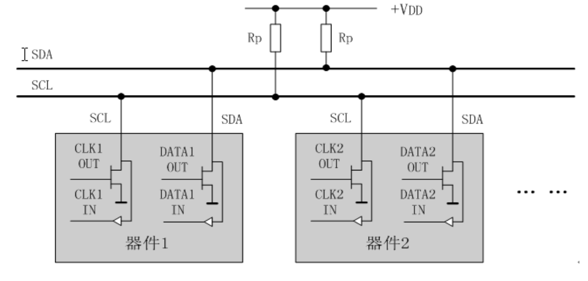
MOS devices use OD (Open Drain) open-drain mode, TTL devices use OC (Open Colletor) collector open-circuit mode. When the device outputs "0", the bus and ground are connected, and when the output "1" is disconnected, so the bus must use external pull-up resistance to pull the bus up to the power supply. Since all devices use OD or OC, output "1" In fact, it does not affect the bus, but because there is pull-up resistance outside, the bus bus line comes out at a high level. When output "0", the device connects to the MOS tube directly when the bus is grounded, the bus is forced to pull to the ground, and the bus becomes low level.
When all devices output "1", the bus shows a high level; When all devices output "0", the bus shows a low level. If part of the output "1" and part of the output "0", the bus level will become "0", which is line "and". Line AND is the result of bus output signal phase AND.
A typical I2C bus application example is shown in the following figure:
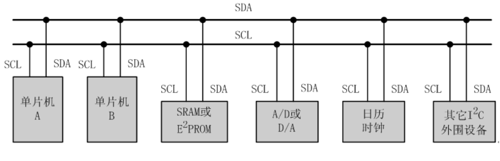
The I2C Bus supports multiple hosts and slaves, and the devices connected on the bus are limited by the bus load of 400pF. With so many devices connected to the bus, each device must have a unique address in order to distinguish the devices. This address is usually 7 digits or 10 digits. A 10 digit address is also called an extended address.
How 2 I2C Bus works
2.1-bit and byte transfers
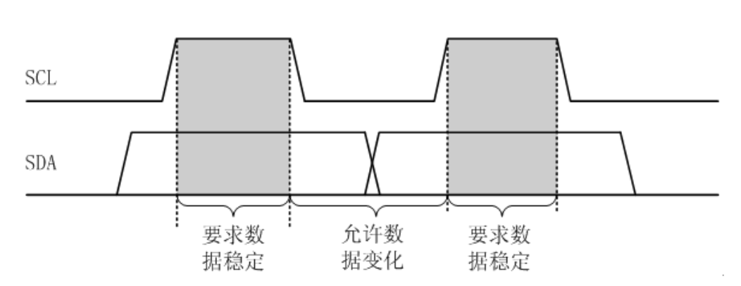
Data validity requirements:
The data on the data bus (SDA) must remain stable during the high clock signal (SCL) period. Changing the data on the SDA is only allowed during the low SCL period, as shown in the following figure:
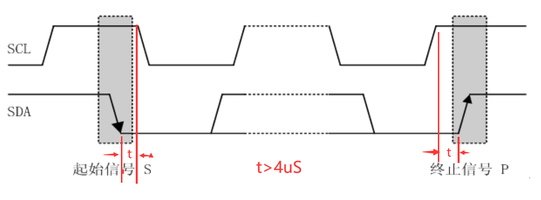
Start and Stop signals:
When the SCL is at a high level, the starting signal of SDA changes from high to low. During a high SCL level, SDA changes from low to high to indicate a termination signal. Standard mode requires t to be greater than 4 microseconds in the graph. Start is generally abbreviated as S and Stop is abbreviated as P.
Answer signal:
Data on the I2C bus is transmitted in 8-bit bytes. Each byte sent by the transmitter (the highest bit MSB of the data is transmitted first), the data line is released during the 9th pulse, and an answer signal is fed back by the receiver. The response signal is at low level and is specified as the effective response bit (ACK); The response signal is at high level and is specified as non-response bit (NACK).
Start Repeated:
In general, the communication process starts with the start signal and the data transfer is completed to end with the end signal. However, in some cases, after transferring part of the data, another communication (typically a write-to-read process) is required to send a restart signal.
Start Repeated is generally abbreviated as Sr.
The minimum time required for the host to send start, end and answer signals is as follows:

2.2 Common data transfer formats
Write Transfer Format
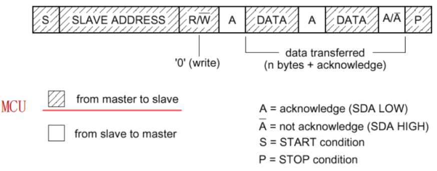
The MCU, as the master device, sends two bytes of data to the slave device. It first sends a start signal (S), then a seven-bit address (MSB high first), then a "0" (write on behalf of), and then a slave confirmation (ACK), followed by a first byte of data (both SCL and S DA signals), and then a second data after slave confirmation. Send a termination signal to end this communication.
Read Transfer Format
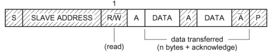
The MCU, as the master device, reads two bytes of data from the slave device, first sends a start signal (S), then sends a 7-bit address (MSB high-bit first), then sends a "1" (representative read), and then receives the first byte of data (SCL signal only, data returned from SDA) after the slave confirmation (ACK), and after receiving 8-bit data, the host sends (ACK); Start receiving the second data, after receiving 8-bit data (if not the first byte, the host sends ACK; if it is the last byte, the host sends NACK), and then send a termination signal to end this communication.
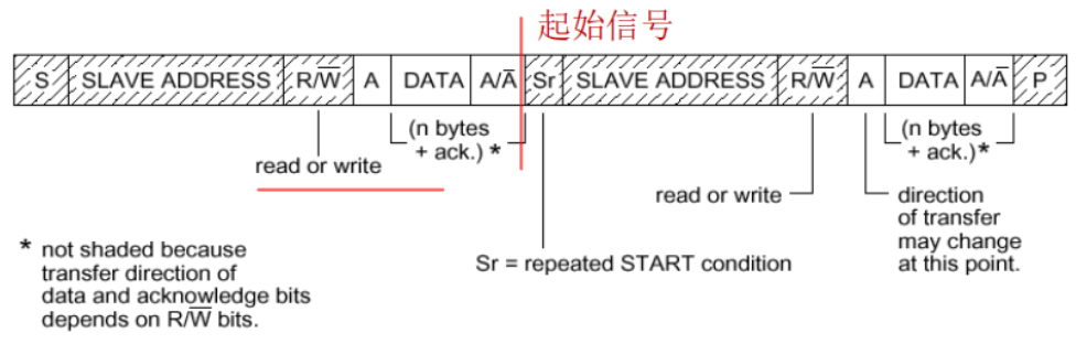
Composite Transport Format
Write and read transmission formats will not change the direction of data transmission throughout the data communication process. If the direction of transmission needs to be changed in the middle of transmission, Sr (restart signal) will be sent in the middle of transmission. Equivalent to a combination of write and read transmission formats.
2.3 Several related definitions
Once you understand these basic concepts, general I2C bus-related programming will be fine. In order not to interfere with beginners, the following concepts are not explained here. Those who want to know more can look for relevant data on their own.
Insert Wait Time
Bus Blocking Status
Bus Competition Arbitration
Synchronization of clock signals
3 Software Analog I2C Host Program
/*
PA8 - SCL
PC9 - SDA

Util_DelayUs Function needs to be defined separately
 The routine uses the standard library function version. If you need to use other library functions, you can modify the related functions yourself.

The routine only defines the basic I2C operation function and refers to the manuals of related devices for specific applications.
*/
static void SCL_GPIO_Init(void)
{
	GPIO_InitStructure.GPIO_Pins = GPIO_Pins_8; //
	GPIO_InitStructure.GPIO_MaxSpeed = GPIO_MaxSpeed_50MHz;
	GPIO_InitStructure.GPIO_Mode = GPIO_Mode_OUT_OD;
	GPIO_Init(GPIOA, &GPIO_InitStructure);
	GPIO_SetBits(GPIOA, GPIO_Pins_8);
	GPIO_InitStructure.GPIO_Pins = GPIO_Pins_9; //
	GPIO_Init(GPIOC, &GPIO_InitStructure);
	GPIO_SetBits(GPIOC, GPIO_Pins_9);
}
static void SCL_OPEN(void)
{
	GPIO_SetBits(GPIOA, GPIO_Pins_8);
}
static void SCL_LOW(void)
{
	GPIO_ResetBits(GPIOA, GPIO_Pins_8);
}
static void SDA_OPEN(void)
{
	GPIO_SetBits(GPIOC, GPIO_Pins_9);
}
static void SDA_LOW(void)
{
	GPIO_ResetBits(GPIOC, GPIO_Pins_9);
}
static uint8_t SCL_READ()
{
	return GPIO_ReadInputDataBit(GPIOA, GPIO_Pins_8);
}
static uint8_t SDA_READ()
{
	return GPIO_ReadInputDataBit(GPIOC, GPIO_Pins_9);
}

static void I2c_GenStart()
{
	SDA_OPEN();
	Util_DelayUs(1);
	SCL_OPEN();
	Util_DelayUs(1);
	SDA_LOW();
	Util_DelayUs(4);  // hold time start condition (t_HD;STA)
	SCL_LOW();
	Util_DelayUs(4);
}
static void I2c_GenStop()
{
	SCL_LOW();
	Util_DelayUs(1);
	SDA_LOW();
	Util_DelayUs(1);
	SCL_OPEN();
	Util_DelayUs(4); // set-up time stop condition (t_SU;STO)
	SDA_OPEN();
	Util_DelayUs(4);
}

static int I2c_WriteByte(uint8_t txByte)
{
	uint8_t mask;
	int Acked = 1;
	for(mask = 0x80; mask > 0; mask >>= 1) { // shift bit for masking (8 times)
		if((mask & txByte) == 0)
			SDA_LOW();    // masking txByte & write to SDA-Line
		else
			SDA_OPEN();
		Util_DelayUs(1);                  // data set-up time (t_SU;DAT)
		SCL_OPEN();                            // generate clock pulse on SCL
		Util_DelayUs(5);                  // SCL high time (t_HIGH)
		SCL_LOW();
		Util_DelayUs(1);                  // data hold time(t_HD;DAT)
	}

	SDA_OPEN();                              // release SDA-line
	SCL_OPEN();                              // clk #9 for ack

	Util_DelayUs(5);                    // data set-up time (t_SU;DAT)
	if(SDA_READ())
		Acked = 0;          // check ack from i2c slave
	SCL_LOW();
	Util_DelayUs(20);                   // wait to see byte package on scope
	return Acked;                            // return error code
}

static uint8_t I2c_ReadByte(int GenAck)
{
	uint8_t mask;
	uint8_t rxByte = 0;
	SDA_OPEN();                              // release SDA-line
	for(mask = 0x80; mask > 0; mask >>= 1) { // shift bit for masking (8 times)
		SCL_OPEN();                            // generate clock pulse on SCL
		Util_DelayUs(1);                  // data set-up time (t_SU;DAT)
		while(SCL_READ() == 0){}                 // wait while hold master
		Util_DelayUs(5);                  // SCL high time (t_HIGH)
		if(SDA_READ()) rxByte = rxByte | mask;   // read bit
		SCL_LOW();
		Util_DelayUs(1);                  // data hold time(t_HD;DAT)
	}
	if(GenAck)
	  SDA_LOW();                // send acknowledge if necessary
	else
	  SDA_OPEN();

	Util_DelayUs(1);                    // data set-up time (t_SU;DAT)
	SCL_OPEN();                              // clk #9 for ack
	Util_DelayUs(5);                    // SCL high time (t_HIGH)
	SCL_LOW();
	SDA_OPEN();                              // release SDA-line
	Util_DelayUs(20);                   // wait to see byte package on scope
	return rxByte;                           // return error code
}