preface
Digital image processing c++ opencv (VS2019 opencv4.53) is continuously updated
1, Homomorphic filtering principle
1. Treatment principle
(1) It is considered that the image f(x,y) consists of two parts: illumination component i(x,y), reflection component r(x,y):
f
(
x
,
y
)
=
i
(
x
,
y
)
∗
r
(
x
,
y
)
f(x,y)=i(x,y)*r(x,y)
f(x,y)=i(x,y)∗r(x,y)
(2) However, the above formula cannot be directly used to process two components in the frequency domain because the Fourier transform of the product is not equal to the product of the transform. Therefore, the definition is:
z
(
x
,
y
)
=
l
n
f
(
x
,
y
)
=
l
n
i
(
x
,
y
)
+
l
n
r
(
x
,
y
)
z(x,y)=lnf(x,y)=lni(x,y)+lnr(x,y)
z(x,y)=lnf(x,y)=lni(x,y)+lnr(x,y)
(3) Fourier transform can be performed after the above transform, including:
Z
(
u
,
v
)
=
F
i
(
u
,
v
)
+
F
r
(
u
,
v
)
Z(u,v)=F_i(u,v)+F_r(u,v)
Z(u,v)=Fi(u,v)+Fr(u,v)
(4) Then a filter H(u,v) can be set to filter Z(u,v):
S
(
u
,
v
)
=
H
(
u
,
v
)
∗
Z
(
u
,
v
)
=
H
(
u
,
v
)
∗
F
i
(
u
,
v
)
+
H
(
u
,
v
)
∗
F
r
(
u
,
v
)
S(u,v)=H(u,v)*Z(u,v)=H(u,v)*F_i(u,v)+H(u,v)*F_r(u,v)
S(u,v)=H(u,v)∗Z(u,v)=H(u,v)∗Fi(u,v)+H(u,v)∗Fr(u,v)
(5) s(x,y) is obtained by inverse Fourier transform for S(u,v), then the filtered image g(x,y):
g
(
x
,
y
)
=
e
s
(
x
,
y
)
g(x,y)=e^{s(x,y)}
g(x,y)=es(x,y)
In the image, it is considered that the low-frequency component is related to the irradiation component, and the high-frequency component is related to the reflection component. Homomorphic filtering is to set a filter H(x,y) and use different controllable methods to affect the influence of low-frequency components and high-frequency components on the image.
2, Homomorphic filter template and MATLAB code
1. Homomorphic filter
(1) The function of Gaussian high pass filter is as follows:
H
(
u
,
v
)
=
1
−
e
−
D
2
(
u
,
v
)
/
2
D
0
2
H(u,v)=1-e^{-D^2(u,v)/2D_0^2}
H(u,v)=1−e−D2(u,v)/2D02
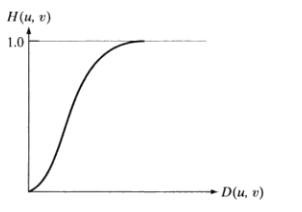
The profile of Gaussian high pass filter is as above, so that the low-frequency component is 0 and the high-frequency component remains unchanged
(2) Homomorphic filter modified with Gaussian high pass filter as template
H ( u , v ) = ( γ H − γ L ) [ 1 − e − C [ D 2 ( u , v ) / 2 D 0 2 ] ] + γ L H(u,v)=(γ_H-γ_L)[1-e^{-C[D^2(u,v)/2D_0^2]}]+γ_L H(u,v)=(γH−γL)[1−e−C[D2(u,v)/2D02]]+γL
his in γ H and γ L gauge set frequency rate of Model around , c control system in between of partial oblique degree among γ_ H and γ_ L specifies the range of frequency, c controls the deviation in the middle among γ H , and γ L ﹤ specify the frequency range, c control the deviation in the middle
When γ H > 1 γ_H>1 γH>1, γ L < 1 γ_L<1 γ When L < 1, the corresponding section is:
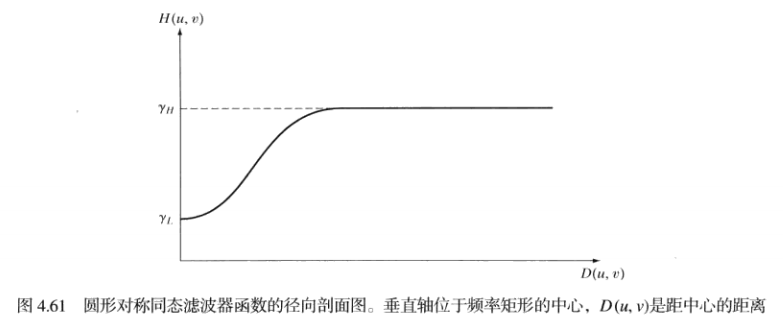
It can be seen that this filter reduces the influence of low-frequency components and increases the influence of high-frequency components.
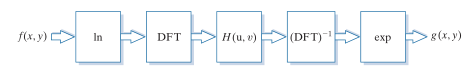
(3) Homomorphic filtering steps:
2. Code
The code is as follows:
#include<iostream>
#include<opencv2/opencv.hpp>
#include "MY_DFT.h"

using namespace cv;
using namespace std;

int main()
{
	Mat image, image_gray, image_output, image_transform;   //Define input image, gray image and output image
	image = imread("lena.png");  //Read the image;
	if (image.empty())
	{
		cout << "Read error" << endl;
		return -1;
	}
	imshow("image", image);

	cvtColor(image, image_gray, COLOR_BGR2GRAY); //Convert to grayscale
	imshow("image_gray", image_gray); //Display grayscale image

	//1. Perform ln transformation
	Mat image_gray2(image_gray.size(), CV_32F);
	for (int i = 0; i < image_gray.rows; i++)
	{
		for (int j = 0; j < image_gray.cols; j++)
		{
			image_gray2.at<float>(i, j) = log(image_gray.at<uchar>(i, j) + 0.1);
		}
	}

	//2. Fourier transform, image_output is the displayable spectrum diagram, image_transform is the complex result of Fourier transform
	My_DFT(image_gray2, image_output, image_transform);
	imshow("image_output", image_output);

	//3. Gaussian high pass filter
	Mat planes[] = { Mat_<float>(image_output), Mat::zeros(image_output.size(),CV_32F) };
	split(image_transform, planes);//Separate channels to obtain real and imaginary parts
	Mat image_transform_real = planes[0];
	Mat image_transform_imag = planes[1];

	int core_x = image_transform_real.rows / 2;//Spectrum center coordinates
	int core_y = image_transform_real.cols / 2;
	int d0 = 10;  //Filter radius
	float h;
	//Parameters:
	float rh = 3;
	float rl = 0.5;
	float c = 5;
	for (int i = 0; i < image_transform_real.rows; i++)
	{
		for (int j = 0; j < image_transform_real.cols; j++)
		{
			h = (rh-rl) * (1 - exp(-c * ((i - core_x) * (i - core_x) + (j - core_y) * (j - core_y)) / (d0 * d0))) + rl;
			image_transform_real.at<float>(i, j) = image_transform_real.at<float>(i, j) * h;
			image_transform_imag.at<float>(i, j) = image_transform_imag.at<float>(i, j) * h;

		}
	}
	planes[0] = image_transform_real;
	planes[1] = image_transform_imag;
	Mat image_transform_ilpf;//Define Gaussian high pass filtering results
	merge(planes, 2, image_transform_ilpf);

	//4. Inverse Fourier transform
	Mat iDft[] = { Mat_<float>(image_output), Mat::zeros(image_output.size(),CV_32F) };
	idft(image_transform_ilpf, image_transform_ilpf);//inverse Fourier transform
	split(image_transform_ilpf, iDft);//Separate channel, mainly obtain channel 0
	magnitude(iDft[0], iDft[1], iDft[0]); //Calculate the amplitude of complex number and save it in iDft[0]
	normalize(iDft[0], iDft[0], 0, 1, NORM_MINMAX);//Normalization processing
	exp(iDft[0], iDft[0]);
	normalize(iDft[0], iDft[0], 0, 1, NORM_MINMAX);//Normalization processing
	iDft[0].convertTo(iDft[0], CV_8U, 255 / 1.0, 0);
	imshow("idft", iDft[0]);//Display inverse transform image
	waitKey(0);  //Pause, hold the image display, and wait for the key to end
	return 0;
}
Fourier transform code (. h file):
#pragma once
#include<iostream>
#include<opencv2/opencv.hpp>
#include<cmath>

using namespace cv;
using namespace std;

void My_DFT(Mat input_image, Mat& output_image, Mat& transform_array);
Fourier transform code (. cpp file):
#include "MY_DFT.h"

//The spectrum and complex domain results are obtained by Fourier transform
void My_DFT(Mat input_image, Mat& output_image, Mat& transform_image)
{
	//1. The operation speed is fast when the extended image matrix is a multiple of 2, 3 and 5
	int m = getOptimalDFTSize(input_image.rows);
	int n = getOptimalDFTSize(input_image.cols);
	copyMakeBorder(input_image, input_image, 0, m - input_image.rows, 0, n - input_image.cols, BORDER_CONSTANT, Scalar::all(0));

	//2. Create a two channel matrix planes to store the real and imaginary parts of the complex number
	Mat planes[] = { Mat_<float>(input_image), Mat::zeros(input_image.size(), CV_32F) };

	//3. Create a multi-channel array from multiple single channel arrays: transform_image.  The function Merge combines several arrays into a multi-channel array, that is, each element of the output array will be a cascade of the input array elements
	merge(planes, 2, transform_image);

	//4. Fourier transform
	dft(transform_image, transform_image);

	//5. Calculate the amplitude of complex number and save it in output_image (spectrum diagram)
	split(transform_image, planes); // The dual channel is divided into two single channels, one represents the real part and the other represents the imaginary part
	Mat transform_image_real = planes[0];
	Mat transform_image_imag = planes[1];

	magnitude(planes[0], planes[1], output_image); //Calculate the amplitude of the complex number and save it in output_image (spectrum diagram)

	//6. The previous spectrum is too large to display, so it is difficult to convert
	output_image += Scalar(1);   // Before taking logarithm, add 1 to all pixels to prevent log0
	log(output_image, output_image);   // Take logarithm
	normalize(output_image, output_image, 0, 1, NORM_MINMAX); //normalization

	//7. Clipping and redistribution amplitude image limit
	output_image = output_image(Rect(0, 0, output_image.cols & -2, output_image.rows & -2));

	// Rearrange the quadrants in the Fourier image so that the origin is in the center of the image
	int cx = output_image.cols / 2;
	int cy = output_image.rows / 2;
	Mat q0(output_image, Rect(0, 0, cx, cy));   // Upper left area
	Mat q1(output_image, Rect(cx, 0, cx, cy));  // Upper right area
	Mat q2(output_image, Rect(0, cy, cx, cy));  // Lower left area
	Mat q3(output_image, Rect(cx, cy, cx, cy)); // Lower right area

	  //Switching quadrant centralization
	Mat tmp;
	q0.copyTo(tmp); q3.copyTo(q0); tmp.copyTo(q3);//Swap top left and bottom right
	q1.copyTo(tmp); q2.copyTo(q1); tmp.copyTo(q2);//Exchange top right and bottom left


	Mat q00(transform_image_real, Rect(0, 0, cx, cy));   // Upper left area
	Mat q01(transform_image_real, Rect(cx, 0, cx, cy));  // Upper right area
	Mat q02(transform_image_real, Rect(0, cy, cx, cy));  // Lower left area
	Mat q03(transform_image_real, Rect(cx, cy, cx, cy)); // Lower right area
	q00.copyTo(tmp); q03.copyTo(q00); tmp.copyTo(q03);//Swap top left and bottom right
	q01.copyTo(tmp); q02.copyTo(q01); tmp.copyTo(q02);//Exchange top right and bottom left

	Mat q10(transform_image_imag, Rect(0, 0, cx, cy));   // Upper left area
	Mat q11(transform_image_imag, Rect(cx, 0, cx, cy));  // Upper right area
	Mat q12(transform_image_imag, Rect(0, cy, cx, cy));  // Lower left area
	Mat q13(transform_image_imag, Rect(cx, cy, cx, cy)); // Lower right area
	q10.copyTo(tmp); q13.copyTo(q10); tmp.copyTo(q13);//Swap top left and bottom right
	q11.copyTo(tmp); q12.copyTo(q11); tmp.copyTo(q12);//Exchange top right and bottom left

	planes[0] = transform_image_real;
	planes[1] = transform_image_imag;
	merge(planes, 2, transform_image);//Centralize Fourier transform results
}
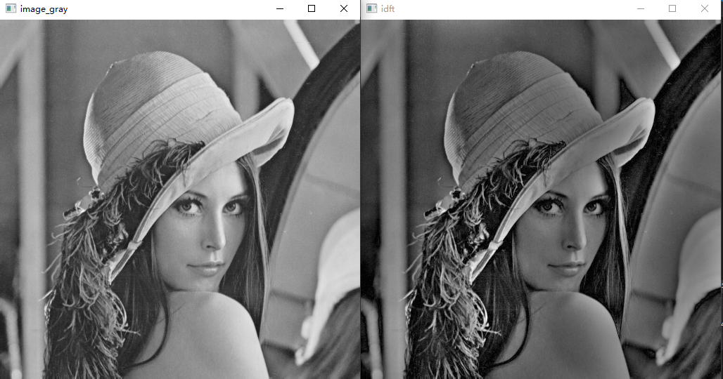
result: