background
The Nb IOT communication chip of XX company is used in the project, and the OPEN-CPU scheme is adopted as the product. In the OPEN-CPU scheme, I understand that it is an application mode with the communication module as the main processor. The advantages will not be discussed. For details, see What does the blogger know . Take this opportunity to understand the interrupt in the NB chip loaded with the Free RTOS system.
Cortex-M interrupt
The MCU of Cortex-M kernel provides a nested vector interrupt controller (NVIC) for interrupt management.
The NVIC of Cotex-M3 supports up to 240 IRQs (interrupt requests), 1 non maskable interrupt (NMI), 1 systick timer interrupt and multiple system exceptions.
Introduction to interrupt management
Cortex-M processor has several programmable registers for managing interrupts and exceptions. Most of these registers are in NVIC and system control block (SCB). CMSIS defines these registers as structures.
typedef struct
{
  __IOM uint32_t ISER[8U];               /*!< Offset: 0x000 (R/W)  Interrupt Set Enable Register */
        uint32_t RESERVED0[24U];
  __IOM uint32_t ICER[8U];               /*!< Offset: 0x080 (R/W)  Interrupt Clear Enable Register */
        uint32_t RSERVED1[24U];
  __IOM uint32_t ISPR[8U];               /*!< Offset: 0x100 (R/W)  Interrupt Set Pending Register */
        uint32_t RESERVED2[24U];
  __IOM uint32_t ICPR[8U];               /*!< Offset: 0x180 (R/W)  Interrupt Clear Pending Register */
        uint32_t RESERVED3[24U];
  __IOM uint32_t IABR[8U];               /*!< Offset: 0x200 (R/W)  Interrupt Active bit Register */
        uint32_t RESERVED4[56U];
  __IOM uint8_t  IP[240U];               /*!< Offset: 0x300 (R/W)  Interrupt Priority Register (8Bit wide) */
        uint32_t RESERVED5[644U];
  __OM  uint32_t STIR;                   /*!< Offset: 0xE00 ( /W)  Software Trigger Interrupt Register */
}  NVIC_Type;
typedef struct
{
  __IM  uint32_t CPUID;                  /*!< Offset: 0x000 (R/ )  CPUID Base Register */
  __IOM uint32_t ICSR;                   /*!< Offset: 0x004 (R/W)  Interrupt Control and State Register */
  __IOM uint32_t VTOR;                   /*!< Offset: 0x008 (R/W)  Vector Table Offset Register */
  __IOM uint32_t AIRCR;                  /*!< Offset: 0x00C (R/W)  Application Interrupt and Reset Control Register */
  __IOM uint32_t SCR;                    /*!< Offset: 0x010 (R/W)  System Control Register */
  __IOM uint32_t CCR;                    /*!< Offset: 0x014 (R/W)  Configuration Control Register */
  __IOM uint8_t  SHP[12U];               /*!< Offset: 0x018 (R/W)  System Handlers Priority Registers (4-7, 8-11, 12-15) */
  __IOM uint32_t SHCSR;                  /*!< Offset: 0x024 (R/W)  System Handler Control and State Register */
  __IOM uint32_t CFSR;                   /*!< Offset: 0x028 (R/W)  Configurable Fault Status Register */
  __IOM uint32_t HFSR;                   /*!< Offset: 0x02C (R/W)  HardFault Status Register */
  __IOM uint32_t DFSR;                   /*!< Offset: 0x030 (R/W)  Debug Fault Status Register */
  __IOM uint32_t MMFAR;                  /*!< Offset: 0x034 (R/W)  MemManage Fault Address Register */
  __IOM uint32_t BFAR;                   /*!< Offset: 0x038 (R/W)  BusFault Address Register */
  __IOM uint32_t AFSR;                   /*!< Offset: 0x03C (R/W)  Auxiliary Fault Status Register */
  __IM  uint32_t PFR[2U];                /*!< Offset: 0x040 (R/ )  Processor Feature Register */
  __IM  uint32_t DFR;                    /*!< Offset: 0x048 (R/ )  Debug Feature Register */
  __IM  uint32_t ADR;                    /*!< Offset: 0x04C (R/ )  Auxiliary Feature Register */
  __IM  uint32_t MMFR[4U];               /*!< Offset: 0x050 (R/ )  Memory Model Feature Register */
  __IM  uint32_t ISAR[5U];               /*!< Offset: 0x060 (R/ )  Instruction Set Attributes Register */
        uint32_t RESERVED0[5U];
  __IOM uint32_t CPACR;                  /*!< Offset: 0x088 (R/W)  Coprocessor Access Control Register */
} SCB_Type;
When multiple interrupts arrive, the processor determines the processing order according to the interrupt priority. High priority interrupts respond first and can preempt low priority interrupts.
Some special priority positions cannot be shaken, such as reset, NMI and HardFault. These interrupt priorities are the highest and fixed.
Priority grouping
Cortex-M processor has 3 fixed priorities and 256 programmable priorities, with a maximum of 128 preemption levels, but the actual number of priorities is determined by the chip manufacturer. The vast majority of chips will simplify the design, so that they actually support fewer priority levels, such as level 8, level 16, level 32, etc.
In order to make preemption more controllable, 256 priorities are divided into high and low ends according to bits, with grouping priority in the front and sub priority in the back. There is a register in NVIC called application interrupt and reset control register AIRCR, which can determine priority groups, accounting for 10 ~ 8 bits of 32-bit register, and can represent 8 kinds of groups, as shown in the following table:
| Grouping location | Bit segment expressing preemption priority | Bit segment expressing sub priority |
|---|---|---|
| 0 (default) | [7:1] | [0:0] |
| 1 | [7:2] | [1:0] |
| 2 | [7:3] | [2:0] |
| 3 | [7:4] | [3:0] |
| 4 | [7:5] | [4:0] |
| 5 | [7:6] | [5:0] |
| 6 | [7:7] | [6:0] |
| 7 | nothing | [7:0] |
Priority Setting
Each external interrupt has a corresponding priority register. Each register occupies 8 bits, so the maximum width is 8 bits, but the minimum is 3 bits. Four adjacent priority registers are combined into a 32-bit register. As mentioned earlier, according to the setting of priority group, priority can be divided into high and low bit segments to preempt priority and sub priority respectively. Priority registers can be accessed by byte or half word / word. The number of meaningful priority registers is realized by the chip manufacturer.
Interrupt masked special register
FreeRTOS needs to focus on PRIMASK, FAULTMASK and BASEPRI registers.
In many applications, it is necessary to temporarily mask all interrupts to perform tasks with strict timing requirements. At this time, the PRIMASK register can be used. PRIMASK is used to prohibit all exceptions and interrupts except NMI and HardFalut. During assembly programming, the CPS (modify processor state) instruction can be used to modify the value of the PRIMASK register:
CPSIE I; // Clear primask (enable interrupt)
CPSID I; // Set primask (no interrupt)
FAULTMASK is more cruel than PRIMASK. It can shield even HardFault. The use method is similar to PRIMASK. FAULTMASK will automatically reset when exiting.
The PRIMASK and FAULTMASK registers are too rough to directly close all interrupts except reset, NMI and HardFault. However, in some cases, it is necessary to control interrupt shielding more finely, such as shielding only interrupts whose priority is lower than a certain threshold. So where is the priority value stored as the threshold? In the BASEPRI register, but if you write 0 to BASEPRI, it will stop masking interrupts.
Interrupt configuration macro
#define portNVIC_SYSPRI2_REG				( * ( ( volatile uint32_t * ) 0xe000ed20 ) )
#define __NVIC_PRIO_BITS                         3U
#define configPRIO_BITS		       __NVIC_PRIO_BITS
#define configLIBRARY_LOWEST_INTERRUPT_PRIORITY			0x7
#define configKERNEL_INTERRUPT_PRIORITY		 ( configLIBRARY_LOWEST_INTERRUPT_PRIORITY << (8 - configPRIO_BITS) )//numeric value 0xe0
#define portNVIC_PENDSV_PRI					( ( ( uint32_t ) configKERNEL_INTERRUPT_PRIORITY ) << 16UL )
#define portNVIC_SYSTICK_PRI				( ( ( uint32_t ) configKERNEL_INTERRUPT_PRIORITY ) << 24UL )
#define configLIBRARY_MAX_SYSCALL_INTERRUPT_PRIORITY	0x1// os api will disable int priority lower than this value when enter critical section
#define configMAX_SYSCALL_INTERRUPT_PRIORITY  0x20//(configLIBRARY_MAX_SYSCALL_INTERRUPT_PRIORITY << (8 - configPRIO_BITS))
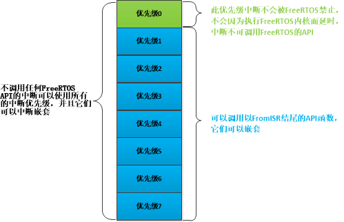
If the priority digit set in NB module is 3, there are 8 priorities in total, of which the lowest logical priority is 7.
The kernel interrupt priority is set to the lowest logical priority 7.
The maximum priority of system interrupt is set to 1.
FreeRTOS functions ending with "FromISR" are protected from interrupt calls (execution of these functions will enter the critical area), but these functions cannot be called by interrupt service functions whose logical priority is higher than the maximum priority of system interrupts. Therefore, the interrupt priority value of any interrupt service routine using RTOSAPI function is greater than or equal to the maximum priority value of system interrupt. It can ensure that the logical priority of interrupt is equal to or lower than the maximum priority of system interrupt.
Cortex interrupts have a priority value of 0 by default. In most cases, 0 represents the highest priority. Therefore, it is absolutely not possible to call the RTOSAPI function in the interrupt service routine with a priority of 0. The specific relationship can be represented by the following figure:
Switch interrupt
The FreeRTOS switch interrupt function is portENABLE_INTERRUPTS() and portDISABLE_INTERRUPTS(), which are actually macro definitions, are defined in portmacro.h as follows:
#define portDISABLE_INTERRUPTS()				vPortRaiseBASEPRI()
#define portENABLE_INTERRUPTS()					vPortSetBASEPRI(0)

static portFORCE_INLINE void vPortSetBASEPRI( uint32_t ulBASEPRI )
{
	__asm
	{
		/* Barrier instructions are not used as this function is only used to
		lower the BASEPRI value. */
		msr basepri, ulBASEPRI
	}
}
static portFORCE_INLINE void vPortRaiseBASEPRI( void )
{
uint32_t ulNewBASEPRI = configMAX_SYSCALL_INTERRUPT_PRIORITY;

	__asm
	{
		/* Set BASEPRI to the max syscall priority to effect a critical
		section. */
		msr basepri, ulNewBASEPRI
		dsb
		isb
	}
}
The function vPortSetBASEPRI() writes a value to the register BASEPRI, which is passed in as the parameter ulBASEPRI, portENABLE_INTERRUPTS() is an interrupt. It passes a 0 to vportsetbasepri (). According to the BASEPRI register we explained earlier, the result is an interrupt.
The function vportraisebaepri() writes configmax to the register baseepri_ SYSCALL_ INTERRUPT_ Priority, then the priority is lower than configMAX_SYSCALL_INTERRUPT_PRIORITY interrupts will be masked!
Critical segment code
Critical segment code, also known as critical area, refers to those code segments that must run completely and cannot be interrupted. For example, the initialization of some peripherals requires strict timing and cannot be interrupted during initialization. FreeRTOS needs to close the interrupt when entering the critical segment code, and then open the interrupt after processing the critical segment code. FreeRTOS system itself has a lot of critical segment code. These codes are protected by critical segment code. We also need to add critical segment code protection in some places when writing our own user programs.
FreeRTOS has four functions related to critical segment code protection: taskENTER_CRITICAL() ,taskEXIT_CRITICAL() ,taskENTER_CRITICAL_FROM_ISR() and taskEXIT_CRITICAL_FROM_ISR(), these four functions are actually macro definitions, which are defined in the task.h file. The difference between these four functions is that the first two are critical segment code protection at task level and the last two are critical segment code protection at interrupt level.