This article is shared from Huawei cloud community< Hongmeng light kernel M kernel source code analysis series 18 Fault exception handling >, author: zhushy.
The Fault exception handling module is related to the OpenHarmony LiteOS-M kernel chip architecture and provides various Fault exception handling for HardFault, MemManage, BusFault, UsageFault, etc. The knowledge related to Cortex-M chip is not discussed in this article. Please refer to cortex-m ™- M7 Devices Generic User Guide and other official materials. This paper first briefly introduces the Fault exception type, vector table and its code, exception handling C language program, and then analyzes the implementation code of exception handling assembly function in detail. The source code involved in this paper, taking OpenHarmony LiteOS-M kernel as an example, can be found on the open source site https://gitee.com/openharmony/kernel_liteos_m obtain.
1. Fault Type exception type
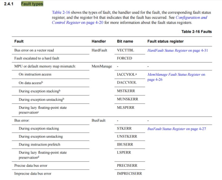
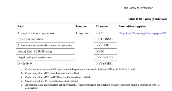
As shown in the Fault type table in the figure below, Fault represents various faults, Handler represents Fault handling mechanism, Bit Name marks the Bit bit of the Fault register, and Fault status register. This figure is taken from Cortex ™- M7 Devices Generic User Guide>.
2. Vector table
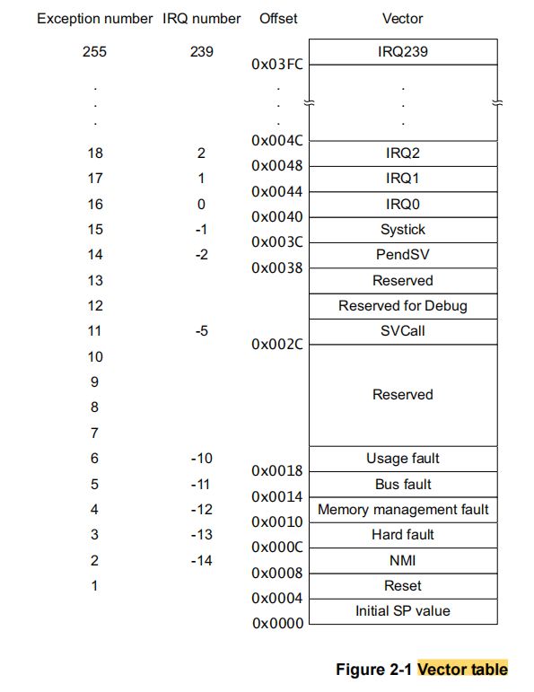
The Vector table contains the reset value and start address of the stack pointer, also known as the exception Vector. Exceptions can be regarded as special interrupts. The corresponding relationship between Exception number, interrupt request number IRQ number, offset value offset and Vector vector is shown in the figure below. This paper mainly focuses on NMI, HardFault, Memory management fault, Bus fault, Usage fault, SVCall and other exceptions.
During interrupt initialization, the exception vector table will be initialized. The code location is kernel\arch\arm\cortex-m7\gcc\los_interrupt.c. HalExcNMI at (1), HalExcHardFault at (2), HalExcMemFault at (3), HalExcBusFault at (4), HalExcUsageFault at (5), HalExcSvcCall at (6). These interrupt exception handling functions are defined in kernel\arch\arm\cortex-m7\gcc\los_exc.S. In this paper, we mainly analyze the code of these assembly functions.
(7) the two lines of code at the beginning are also important. The corresponding exception can be made by changing the bit bit bit of the System Handler Control and State Register, and the exception can be cleared by changing the bit bit bit of the Configuration and Control Register.
LITE_OS_SEC_TEXT_INIT VOID HalHwiInit(VOID)
{
#if (LOSCFG_USE_SYSTEM_DEFINED_INTERRUPT == 1)
    UINT32 index;
    g_hwiForm[0] = 0;             /* [0] Top of Stack */
    g_hwiForm[1] = Reset_Handler; /* [1] reset */
    for (index = 2; index < OS_VECTOR_CNT; index++) { /* 2: The starting position of the interrupt */
        g_hwiForm[index] = (HWI_PROC_FUNC)HalHwiDefaultHandler;
    }
    /* Exception handler register */
⑴  g_hwiForm[NonMaskableInt_IRQn + OS_SYS_VECTOR_CNT]   = HalExcNMI;
⑵  g_hwiForm[HARDFAULT_IRQN + OS_SYS_VECTOR_CNT]        = HalExcHardFault;
⑶  g_hwiForm[MemoryManagement_IRQn + OS_SYS_VECTOR_CNT] = HalExcMemFault;
⑷  g_hwiForm[BusFault_IRQn + OS_SYS_VECTOR_CNT]         = HalExcBusFault;
⑸  g_hwiForm[UsageFault_IRQn + OS_SYS_VECTOR_CNT]       = HalExcUsageFault;
⑹  g_hwiForm[SVCall_IRQn + OS_SYS_VECTOR_CNT]           = HalExcSvcCall;
    g_hwiForm[PendSV_IRQn + OS_SYS_VECTOR_CNT]           = HalPendSV;
    g_hwiForm[SysTick_IRQn + OS_SYS_VECTOR_CNT]          = SysTick_Handler;

    /* Interrupt vector table location */
    SCB->VTOR = (UINT32)(UINTPTR)g_hwiForm;
#endif
#if (__CORTEX_M >= 0x03U) /* only for Cortex-M3 and above */
    NVIC_SetPriorityGrouping(OS_NVIC_AIRCR_PRIGROUP);
#endif

    /* Enable USGFAULT, BUSFAULT, MEMFAULT */
⑺  *(volatile UINT32 *)OS_NVIC_SHCSR |= (USGFAULT | BUSFAULT | MEMFAULT);
    /* Enable DIV 0 and unaligned exception */
    *(volatile UINT32 *)OS_NVIC_CCR |= DIV0FAULT;

    return;
}
3. HalExcHandleEntry exception handler C Entry
The HalExcHandleEntry exception handling function is the entry for the assembly exception function to jump to the C language program, which is defined in the file kernel\arch\arm\cortex-m7\gcc\los_interrupt.c, by kernel \ arch \ arm \ cortex-m7 \ GCC \ Los_ Assembly function call in exc.s file. The function parameters are passed in by R0-R3 registers in the assembler. The corresponding relationship between registers in the assembler and HalExcHandleEntry function parameters is shown in the table below:
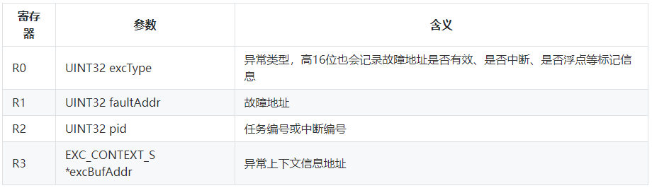
Next, we analyze the source code of the function. The label at (1) indicates the high 16 bits of the exception type parameter, which is used for the characteristic mark, mainly to mark whether the fault address is valid, whether the fault occurs in an interrupt, whether floating point is supported, etc. (2) increase the interrupt count and the number of nested exceptions at. (3) record the exception type. If a valid fault address is recorded at (4), obtain the fault address. (5) if the current running task exists, if it is marked that the exception occurs in the interrupt, record the interrupt number and record that the exception occurs in the interrupt; otherwise, record the task number and record that the exception occurs in the task. If the current running task is empty, the exception occurs in the initialization phase. (6) if the exception type contains a flag that supports floating point numbers, handle it accordingly. (7) output abnormal information to the console.
LITE_OS_SEC_TEXT_INIT VOID HalExcHandleEntry(UINT32 excType, UINT32 faultAddr, UINT32 pid, EXC_CONTEXT_S *excBufAddr)
{
⑴  UINT16 tmpFlag = (excType >> 16) & OS_NULL_SHORT; /* 16: Get Exception Type */
⑵  g_intCount++;
    g_excInfo.nestCnt++;

⑶  g_excInfo.type = excType & OS_NULL_SHORT;

⑷  if (tmpFlag & OS_EXC_FLAG_FAULTADDR_VALID) {
        g_excInfo.faultAddr = faultAddr;
    } else {
        g_excInfo.faultAddr = OS_EXC_IMPRECISE_ACCESS_ADDR;
    }
⑸  if (g_losTask.runTask != NULL) {
        if (tmpFlag & OS_EXC_FLAG_IN_HWI) {
            g_excInfo.phase = OS_EXC_IN_HWI;
            g_excInfo.thrdPid = pid;
        } else {
            g_excInfo.phase = OS_EXC_IN_TASK;
            g_excInfo.thrdPid = g_losTask.runTask->taskID;
        }
    } else {
        g_excInfo.phase = OS_EXC_IN_INIT;
        g_excInfo.thrdPid = OS_NULL_INT;
    }
⑹  if (excType & OS_EXC_FLAG_NO_FLOAT) {
        g_excInfo.context = (EXC_CONTEXT_S *)((CHAR *)excBufAddr - LOS_OFF_SET_OF(EXC_CONTEXT_S, uwR4));
    } else {
        g_excInfo.context = excBufAddr;
    }

⑺  OsDoExcHook(EXC_INTERRUPT);
    OsExcInfoDisplay(&g_excInfo);
    HalSysExit();
}
4,Los_Exc exception handling assembler function
When introducing the Vector table above, it has been mentioned in the file kernel \ arch \ arm \ cortex-m7 \ GCC \ LOS_ The exception handling functions defined in exc.s are as follows. When Fault exceptions occur, these exception handling functions will be scheduled and executed. This section will analyze the source code of the function in detail to master how the kernel handles these exceptions. The processing process of these six functions is similar. We select two typical functions for analysis.
    .global  HalExcNMI
    .global  HalExcHardFault
    .global  HalExcMemFault
    .global  HalExcBusFault
    .global  HalExcUsageFault
    .global  HalExcSvcCall
4.1 HalExcNMI
When NMI (Non Maskable Interrupt) occurs, HalExcNMI assembly function will be triggered. The execution flow of this function is shown in the following figure. The function code will be read below in conjunction with the flowchart.
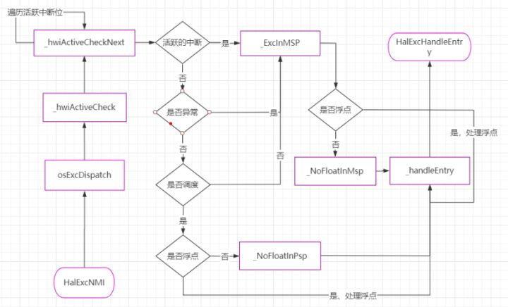
HalExcNMI function code is as follows: assign OS to R0 register at (1)_ EXC_ CAUSE_ NMI, which is equal to 16, corresponding to the file kernel \ arch \ arm \ cortex-m7 \ GCC \ LOS_ arch_ The exception type macro in interrupt. H defines the OS_EXC_CAUSE_NMI, all 16. This value corresponds to the first parameter of the HalExcHandleEntry function. (2) set the fault address at, which corresponds to the second parameter of HalExcHandleEntry function. (3) jump to the function osExcDispatch to continue execution.
    .type HalExcNMI, %function
    .global HalExcNMI
HalExcNMI:
    .fnstart
    .cantunwind
⑴  MOV  R0, #OS_EXC_CAUSE_NMI
⑵  MOV  R1, #0
⑶  B  osExcDispatch
    .fnend
Some of the functions analyzed below are more general, and other exception handling functions will also be called.
4.1.1 osExcDispatch function
The osExcDispatch function code is as follows, and the Interrupt Active Bit Registers base address is loaded at (1). There are 8 Interrupt Active Bit Registers, NVIC_IABR0-NVIC_IABR7, each register contains 32 bits, can correspond to 32 interrupt numbers, and supports 256 interrupts in total. The bit bits 0 ~ 31 of IABR[0] correspond to interrupt numbers 0 ~ 31 respectively; Bit bits 0 ~ 31 of IABR[1] correspond to interrupts 32 ~ 63; Others, and so on. ⑵ set the cycle count at, corresponding to 8 registers. Later, we will cycle through 8 registers to query whether there are active interrupts.
    .type osExcDispatch, %function
    .global osExcDispatch
osExcDispatch:
    .fnstart
    .cantunwind
⑴  LDR   R2, =OS_NVIC_ACT_BASE
⑵  MOV   R12, #8                       // R12 is hwi check loop counter
    .fnend
4.1.2 _hwiActiveCheck function
After executing the above osExcDispatch function code, the subsequent functions will continue to be executed_ hwiActiveCheck code. (1) read the value of the active bit register, and then execute (2) compare the value of the register with the size of 0. If it is equal, it indicates that the interrupt corresponding to the active bit register is not active, and then jump to_ hwiActiveCheckNext. If it is not equal to 0, execute (3) and the upper 16 bits of the parameter type are marked as interrupt. (4) the code at 4 calculates the interrupt number according to the interrupt active bit and assigns it to register R2, which corresponds to the third parameter of HalExcHandleEntry function. The specific calculation method is to first reverse the value R3 of the active interrupt bit register and save it to R2, and then calculate the number of high bits 0. Add 1 to the count value R12, then move 5 bits to the left (equal to multiplying by 32), and then add R2, which is the interrupt number.
    .type _hwiActiveCheck, %function
    .global _hwiActiveCheck
_hwiActiveCheck:
    .fnstart
    .cantunwind
⑴  LDR   R3, [R2]                      // R3 store active hwi register when exc
⑵  CMP   R3, #0
    BEQ   _hwiActiveCheckNext

    // exc occurred in IRQ
⑶  ORR   R0, R0, #FLAG_HWI_ACTIVE
⑷  RBIT  R2, R3
    CLZ   R2, R2
    AND   R12, R12, #1
    ADD   R2, R2, R12, LSL #5               // calculate R2 (hwi number) as pid
    .fnend
4.1.3 _ExcInMSP functions and_ NoFloatInMsp function
If there is an active interrupt, continue to execute the subsequent code. The main stack processing function used when processing interrupts_ ExcInMSP. (1) compare the size of the abnormal return value and #0xfffffed at. If they are equal, it indicates that floating-point calculation is supported, and then continue to execute the subsequent code. If they are not equal, they do not support floating-point calculation, and jump to the function_ NoFloatInMsp function. For more information about exception return values, refer to the Cortex ™- M7 Devices Generic User Guide Table 2-15 Exception return behavior.
If floating-point calculation is supported, execute (2) to assign the stack pointer plus 104 to R3 register, and then press the stack. This value corresponds to the fourth parameter of HalExcHandleEntry function. The size of 104 should come from the structure EXC_CONTEXT_S. (3) copy the PRIMASK value of register to R12 register, and then stack R4-R12 registers. Press the floating-point register on the stack at (4) and jump to the function at (5)_ handleEntry.
Executes a function when floating-point calculations are not supported_ NoFloatInMsp. (6) assign the stack pointer plus 32 to R3 register, and then press the stack. This value corresponds to the fourth parameter of HalExcHandleEntry function. Then stack R3, copy the value of register PRIMASK to R12, and then stack R4-R12. The difference with floating-point support is that there is no need to stack D8-D15 registers. (7) mark the high bit of the parameter type with the mark that does not support floating point, and then jump to the function_ handleEntry.
    .type _ExcInMSP, %function
    .global _ExcInMSP
_ExcInMSP:
    .fnstart
    .cantunwind
⑴  CMP   LR, #0XFFFFFFED
    BNE   _NoFloatInMsp
⑵  ADD   R3, R13, #104
    PUSH  {R3}
⑶  MRS   R12, PRIMASK                  // store message-->exc: disable int?
    PUSH {R4-R12}                       // store message-->exc: {R4-R12}
#if ((defined(__FPU_PRESENT) && (__FPU_PRESENT == 1U)) && \
     (defined(__FPU_USED) && (__FPU_USED == 1U)))
⑷  VPUSH {D8-D15}
#endif
⑸  B     _handleEntry
  .fnend

    .type _NoFloatInMsp, %function
    .global _NoFloatInMsp
_NoFloatInMsp:
    .fnstart
    .cantunwind
⑹  ADD   R3, R13, #32
    PUSH  {R3} // save IRQ SP            // store message-->exc: MSP(R13)

    MRS   R12, PRIMASK                  // store message-->exc: disable int?
    PUSH {R4-R12}                       // store message-->exc: {R4-R12}
⑺  ORR   R0, R0, #FLAG_NO_FLOAT
    B     _handleEntry
  .fnend
4.1.4 _hwiActiveCheckNext function
When traversing the interrupt active bit register, if there is no active interrupt in the previous register, the function is executed_ hwiActiveCheckNext determines whether the next register has an active interrupt. (1) offset the address of the active bit register by 4 bytes and reduce the count by 1. If there are other active bit registers, jump to the function_ hwiActiveCheck continues to judge. Otherwise, execute the subsequent code, load the address of the system handler control and state register (SHCSRS) system processing control and state register at (2), and then load the half byte value. (3) load mask 0xC00 at, and the 10th and 11th bits of the binary value are 1. Bit 11 of SHCSRS register corresponds to SysTick abnormally active bit, and bit 10 corresponds to PendSV abnormally active bit. (4) perform logic and calculation at R2 and R3, and then compare the result with 0. If the result is 0, it indicates that there is no ysTick exception or PendSV exception. If the result is 1, it indicates that an exception has occurred, and you need to execute (5) to jump to the function_ ExcInMSP continues, and the function has been analyzed above. Get the global variable g at (6)_ The address of taskscheduled, and then get its value and compare it with 1. If it is equal to 1, the system has started task scheduling and will continue to execute subsequent codes. If it is not 1, the system is not scheduled and is in the initialization stage. You need to jump to the function_ ExcInMSP continues.
If the system starts task scheduling, use the process stack PSP to execute (7) to judge whether the system supports floating-point calculation. Continue if supported, otherwise jump to the function_ NoFloatInPsp. Code and function starting at (8)_ Nofloatinpsp can be read in contrast. The former requires stack floating-point registers, while the latter does not. (8) copy the stack pointer to the R2 register, and then subtract 96 from the stack pointer. (9) assign the PSP thread stack pointer value to R3 register, and then assign R3 plus 104 to register R12. The calculated value is the task stack pointer, and then press the stack.
(10) copy the value of PRIMASK register to R12, then stack registers R4-R12, and then stack floating-point registers D8-D15. (11) stack R4-R11 and D8-D15 from PSP stack pointer, and then stack D8-D15 and R4-R11 from R13 stack pointer. Jump to function at (12)_ handleEntry continues to point to.
    .type _hwiActiveCheckNext, %function
    .global _hwiActiveCheckNext
_hwiActiveCheckNext:
    .fnstart
    .cantunwind
⑴  ADD   R2, R2, #4                        // next NVIC ACT ADDR
    SUBS  R12, R12, #1
    BNE   _hwiActiveCheck

    /*NMI interrupt exception*/
⑵  LDR   R2, =OS_NVIC_SHCSRS
    LDRH  R2,[R2]
⑶  LDR   R3,=OS_NVIC_SHCSR_MASK
⑷  AND   R2, R2,R3
    CMP   R2,#0
⑸  BNE   _ExcInMSP
    // exc occured in Task or Init or exc
    // reserved for register info from task stack

⑹  LDR  R2, =g_taskScheduled
    LDR  R2, [R2]
    TST  R2, #1                         // OS_FLG_BGD_ACTIVE
    BEQ  _ExcInMSP                      // if exc occurred in Init then branch
⑺  CMP   LR, #0xFFFFFFED               //auto push floating registers
    BNE   _NoFloatInPsp

    // exc occurred in Task
⑻  MOV   R2,  R13
    SUB   R13, #96                      // add 8 Bytes reg(for STMFD)

⑼  MRS   R3,  PSP
    ADD   R12, R3, #104
    PUSH  {R12}                         // save task SP

⑽  MRS   R12, PRIMASK
    PUSH {R4-R12}
    VPUSH {D8-D15}

    // copy auto saved task register

⑾  LDMFD R3!, {R4-R11}                  // R4-R11 store PSP reg(auto push when exc in task)
    VLDMIA  R3!, {D8-D15}
    VSTMDB  R2!, {D8-D15}
    STMFD R2!, {R4-R11}
⑿  B     _handleEntry
  .fnend

    .type _NoFloatInPsp, %function
    .global _NoFloatInPsp
_NoFloatInPsp:
    .fnstart
    .cantunwind
    MOV   R2,  R13                      // no auto push floating registers
    SUB   R13, #32                      // add 8 Bytes reg(for STMFD)

    MRS   R3,  PSP
    ADD   R12, R3, #32
    PUSH  {R12}                         // save task SP

    MRS   R12, PRIMASK
    PUSH {R4-R12}

    LDMFD R3, {R4-R11}                  // R4-R11 store PSP reg(auto push when exc in task)
    STMFD R2!, {R4-R11}
    ORR   R0, R0, #FLAG_NO_FLOAT
  .fnend
4.1.5 _handleEntry function
Continue analyzing functions_ handleEntry. The code is very simple. (1) copy the stack pointer to R3, which corresponds to the fourth parameter of HalExcHandleEntry function. (2) close the interrupt, close the Fault exception, and then execute (2) jump to the C language function HalExcHandleEntry.
_handleEntry:
    .fnstart
    .cantunwind
⑴  MOV R3, R13                         // R13:the 4th param
⑵  CPSID I
    CPSID F
    B  HalExcHandleEntry

    NOP
  .fnend
4.2 HalExcUsageFault
When a usage exception UsageFault occurs, the HalExcUsageFault assembly function will be triggered. The execution flow of the function is shown in the following figure. The function code will be read below in conjunction with the flowchart.
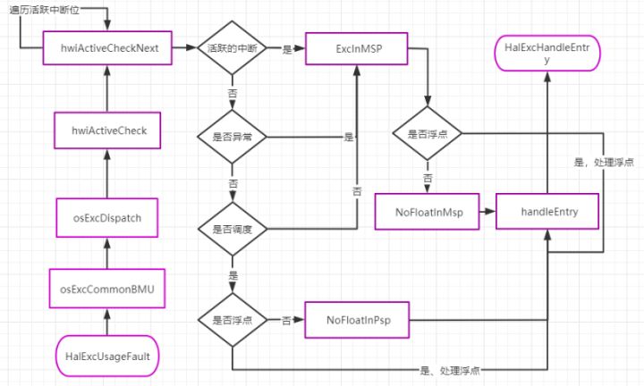
The HalExcUsageFault function code is as follows: (1) copy the address of the Configurable Fault Status Register (CFSR) to the R0 register, and then read the register value to the R0 register. (2) assign 0x030F to R1 register, and then move it to the left by 16 bits. UsageFault Status Register the validity of the fault status register is as follows: 0-3 and 8-9 are significant bits, and the binary of 0x030F corresponds to these significant bits. (3) perform logic and at, so as to calculate the bit corresponding to the actual service fault. (4) assign R12 to 0, and then continue to execute the subsequent assembly code osexcommonbmu.
    .type HalExcUsageFault, %function
    .global HalExcUsageFault
HalExcUsageFault:
    .fnstart
    .cantunwind
⑴  LDR  R0, =OS_NVIC_FSR
    LDR  R0, [R0]

⑵  MOVW  R1, #0x030F
    LSL  R1, R1, #16
⑶  AND  R0, R0, R1
⑷  MOV  R12, #0

    .fnend
4.2.1 g_uwExcTbl array
Before looking at the code of osexcommonbmu function, you need to know the following g_uwExcTbl array, G_ The uwexctbl array is defined in the file kernel\arch\arm\cortex-m7\gcc\los_interrupt.c, the code is as follows.
The array contains 32 elements, each element corresponds to a bit of CFSR register, and the element value is defined as the exception type in LiteOS-M. Like OS_EXC_UF_DIVBYZERO is equal to exception type 10 and is a divide by zero exception.
UINT8 g_uwExcTbl[FAULT_STATUS_REG_BIT] = {
    0, 0, 0, 0, 0, 0, OS_EXC_UF_DIVBYZERO, OS_EXC_UF_UNALIGNED,
    0, 0, 0, 0, OS_EXC_UF_NOCP, OS_EXC_UF_INVPC, OS_EXC_UF_INVSTATE, OS_EXC_UF_UNDEFINSTR,
    0, 0, 0, OS_EXC_BF_STKERR, OS_EXC_BF_UNSTKERR, OS_EXC_BF_IMPRECISERR, OS_EXC_BF_PRECISERR, OS_EXC_BF_IBUSERR,
    0, 0, 0, OS_EXC_MF_MSTKERR, OS_EXC_MF_MUNSTKERR, 0, OS_EXC_MF_DACCVIOL, OS_EXC_MF_IACCVIOL
};
4.2.2 osexcommonbmu function
Now let's analyze the assembly code osexcommonbmu. (1) calculate the number of high-order zeros of R0 value and load the array global variable g_uwExcTbl address to R3 register, and then execute ⑵ to calculate the number of array elements, and load the element value to R0 register. ⑶ there is no effect when R0 and R12 carry out logic or operation. R0 corresponds to the first parameter of the HalExcHandleEntry function. The osExcDispatch function will continue to be executed later, which has been analyzed earlier.
    .type osExcCommonBMU, %function
    .global osExcCommonBMU
osExcCommonBMU:
    .fnstart
    .cantunwind
⑴  CLZ  R0, R0
    LDR  R3, =g_uwExcTbl
⑵  ADD  R3, R3, R0
    LDRB R0, [R3]
⑶  ORR  R0, R0, R12
    .fnend
Summary
This paper introduces the Fault exception type, vector table and its code, exception handling C language program, exception handling assembly function implementation code. Thank you for reading. If you have any questions and suggestions, you can leave a message to me under the blog. Thank you.
reference material
- Cortex™-M7 Devices Generic User Guide Download
Click focus to learn about Huawei cloud's new technologies for the first time~